


12
SMARTHUB
2.6.1.Validation Test 1 (using external power supply)
a.Connect the device to the external power supply
•
Connect the AC adapter to the electric socket
•
Connect the BLACK alligator clip to the device PINK wire (ground)
•
Connect the RED alligator clip to the device RED wire (power)
•
The unit should power on, with all LED lights flashing for 3 seconds
b.Test default signals (default values)
•
Remove all batteries from simulation tags
•
Connect the multi-meter (fluke) BLACK line to the PINK wire (ground)
•
Do not disconnect the adaptor line
•
Turn on the multi-meter and set dial to DC detection
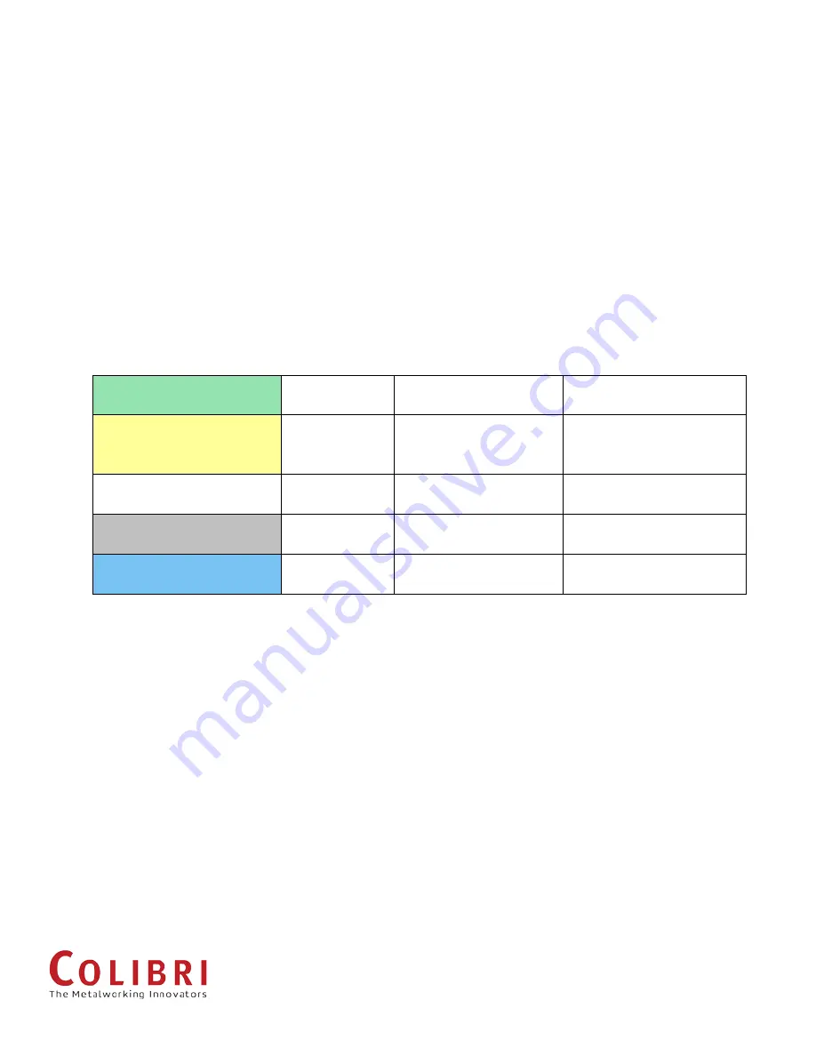
Power-on (GREEN wire)
Default state is
HIGH
Touch GREEN wire with
multi-meter RED point
Reading should show
22.5V ~ 23.9V
Low-RSSI (YELLOW wire)
Default state is
LOW
Touch YELLOW wire
with multi-meter RED
point
Reading should show ~ 0V
Low-battery (WHITE wire)
Default state is
LOW
Touch WHITE wire with
multi-meter RED point
Reading should show ~ 0V
Zero RPM (GREY wire)
Default state is
HIGH
Touch GREY wire with
multi-meter RED point
Reading should show
22.5V ~ 23.9V
High/low RPM (BLUE wire)
Default state is
LOW
Touch BLUE wire with
multi-meter RED point
Reading should show ~ 0V
c.Test live signals (during spindle operation)
•
Make sure SmartHUB power is on (BLUE and GREEN lights should be lit)
•
Turn on Tablet display
•
Tap "Devices" to see the list of connected devices
•
Remove all devices by tapping the "X" button
•
Insert battery into one simulation tag (note ID on the side)
•
Connect the simulation tag to the SmartHUB by tapping "Add Device" on the
application and entering simulation tag ID (1003 / 1004)
•
Check the tag is connected by returning to the main screen. If no information is
displayed on the main screen, reboot Tablet and reconnect
•
When simulated graphs appear, check the signals to see if the state (High/Low)
changes as follows:


