background image

COFFE

tek 

LTD


BEAN TO CUP 

Issue 1 

01/12/2005 

10 


WATER SYSTEM 

14. 

The main water supply enters the machine via a double chamber inlet valve, which is 
mounted in the cabinet base panel.  A length of tube then takes the water supply into the 
top of the water boiler via an air break into a channel, which is directed, to the bottom of the 
heater tank. 

15. 

Hot water is dispensed from the boiler, via the appropriate solenoid operated valve, to the 
mixing bowl.  A length of tube directs any overflow from the boiler via overtemp safety 
thermostats to the waste tray. 

16. 

The cold water mains supply enters the machine at the base of the cabinet and connects 
with a dual chamber solenoid operated inlet valve, which controls the flow of water to the 
boiler. The water is maintained at a constant level in response to signals from a water level 
probe which is connected to the Controller Board. 

17. 

The water is heated to the required temperature by a single or up to 3 heating elements 
subject to configuration.  The Controller Board ensures that the temperature is maintained 
to a predetermined level by controlling the supply to the heater in response to signals from 
the N.T.C. temperature sensor which forms part of the level/temperature probe assembly. 

18. 

Hot water from the boiler is fed directly to the mixing bowls where it mixes with the 
dispensed ingredient to produce the selected beverage.  Solenoid operated valves 
distribute the hot water to the selected mixing bowl, the amount of water being determined 
by the program setting. 

19. 

The temperature of the water, is monitored by the Controller Board via a sensor inserted 
into the tank, thus causing the supply to the heater to be removed when the water in the 
boiler reaches its required temperature setting.  If the temperature in the boiler increases 
causing the water to boil over, the water will flow down the overflow pipe over the overtemp 
sensors which will cut off the electrical supply to the heating elements.  These sensors are 
mounted on the cabinet rear and are re-settable. 

Heater Control and Boosting 

20.  The heating control system employs an intelligent algorithm to obtain maximum 

performance as follows:- 

Boost operation takes place when the inlet valve opens following a selection being taken. The 
heater control algorithm is instructed to turn on both SSR’s for the duration specified in the 
variable CUP BOOST  referred to Section 2 paragraph 24. 

If the temperature is 50 more than the DESIRED TEMPERATURE, set in the CHANGE 
SETTING MENU (see Section 2 paragraph 24) all boosting operations are disabled.  

If the actual temperature is between 0 – 35 less than the DESIRED TEMPERATURE one SSR 
is OFF and the other one toggles ON & OFF unless a boost operation is in progress then both 
SSR are ON. 

If the actual temperature is between 35 - & 50 less than the desired temperature one SSR is 
ON and the other is OFF. Boost operations are as above. 

If the actual temperature is more than 50 below the desired temperature both SSR’s are ON. 

Содержание BEAN TO CUP

Страница 1: ...BEAN TO CUP BEVERAGE MACHINE TECHNICAL MANUAL ...

Страница 2: ...Overflow Protection 11 ELECTRICAL AND ELECTRONIC SYSTEM 12 Functional Description 12 Circuit Description 13 SECTION 2 PROGRAMMING 14 INTRODUCTION 14 INTERNAL KEYPAD LAYOUT 15 KEYPAD FUNCTIONS 15 OPERATOR PROGRAM 16 ENGINEER PROGRAM 17 Accessing the Engineers Mode 17 Program Options 18 SECTION 3 INSTALLATION AND MAINTENANCE 26 INTRODUCTION 26 SAFETY WARNINGS 27 FROST WARNING 27 INSTALLATION 28 Loca...

Страница 3: ...FEtek LTD 3 01 12 2005 Issue 1 BEAN TO CUP DAILY HYGIENE 35 Cleaning 35 Filling 37 Flushing 37 WEEKLY HYGIENE 38 Cleaning 38 Filling Procedure 39 FAULT FINDING GUIDE 40 SECTION 4 EXPLODED PARTS DIAGRAM 42 ...

Страница 4: ...in the manual 2 Personnel who have undergone relevant equipment training must only undertake maintenance of the beverage machine 3 The manufacturer reserves the right to make changes without notice to the design of the beverage machine which may affect the information contained in this manual 4 The Bean To Cup Beverage Machine is designed for indoor use in an environment with an ambient temperatur...

Страница 5: ...COFFEtek LTD 5 01 12 2005 Issue 1 BEAN TO CUP This page is intentionally blank ...

Страница 6: ... head and the selection is made via a pushbutton The drink is then dispensed in the required quantity The machine does not accept money but a feature such as this can be added 3 The status of the machine may be monitored and the configuration altered by accessing a program using the keypad and display The program offers a menu of options each consisting of a number of sub options which can be alte...

Страница 7: ...TH CM 51 WEIGHT KG 26 TANK CAPACITY LITRE 2 5 CANISTER CAPACITY GRAM DETAILS FRESH COFFEE BEANS 1 5Kg CHOCOLATE 1500g TOPPING 1000g MENU OPTIONS SELECTIONS 8 DISPENSE TIME PER CUP SEC POWER 3KW CUP SERVING HOUR 180 MAINS WATER PORTABLE YES YES MAX MIN PRESSURE BAR MIN 1 MAX 8 ILLUMINATED BUTTONS YES BACK PANEL YES SELF CLEANING BUTTON YES ...

Страница 8: ...A b The fused electrical supply should terminate at an appropriate isolator located within 1m of the beverage machine Water Supply 7 a 15mm dia Water mains supply terminating at a convenient stop tap located within 1m of the beverage machine b Water pressure 1 bar minimum 8 bar maximum c A 15mm double backcheck valve with inspection port should be fitted prior to the flexible hose ...

Страница 9: ...ense head A plastic agitator is located inside of the milk topping and chocolate canister to ensure free and consistent flow of product Additionally a whipper unit located beneath the mixing bowls ensures that the product and water are correctly mixed The ingredient canisters must be removed for filling of the products and when all four canisters are removed and steam hoods of the mixing bowls are...

Страница 10: ...noid operated valves distribute the hot water to the selected mixing bowl the amount of water being determined by the program setting 19 The temperature of the water is monitored by the Controller Board via a sensor inserted into the tank thus causing the supply to the heater to be removed when the water in the boiler reaches its required temperature setting If the temperature in the boiler increa...

Страница 11: ...ed by switching the machine off and on Note An empty tank may take several cycles to fill completely 22 The second protective mechanism is designed to act as a fail safe in the event that a slow leak occurs which does not result in the liquid entering the drip tray The machine will cease all attempts to fill the tank after 20 tank top ups have been made if no selections have been taken in the mean...

Страница 12: ...riate 25 The main System Program tasks the microprocessor with continually checking the status of the input devices keypad probe etc and responding to data received by signalling the output devices LCD display motors whippers etc to take the appropriate action The System Program also requests the microprocessor to interrogate the variable settings in NVRAM and to modify its actions accordingly 26 ...

Страница 13: ...ply PCB via the on off switch The Power Supply PCB provides DC supplies of 24V 12V and 5V The 24V dc output supplies the ingredient motors whipper motors extract fan SSR and solenoid operated valves The 12V dc output supplies the MPU Controller Board and operational coin acceptor if fitted 30 The MPU Controller Board continually checks the status of input devices connected to plugs J1 and J3 and r...

Страница 14: ......

Страница 15: ...le to both the Operator and the Service engineer but the Engineer s Program is only available to the SERVICE ENGINEER 2 Both the programs are stored in programmable read only memory on the Controller Board The values and settings Variables which the program allows the programmer to alter are store in NVRAM non volatile random access memory 3 Settings are maintained with out the need for back up ba...

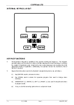
Страница 16: ...otal vends dispensed and resetting the drink dispensed counters if applicable Additionally the operator can set the machine to Out of Service if required 5 Keypad functions when used in the Operator s programming mode are as follows 1 Key ENTER used to access a function 2 Key PROG used to access the operators program then used to change menu functions 3 ARROWS UP DOWN À LEFT RIGHT are used for adj...

Страница 17: ...own on the keypad in turn 8 To access other options press PROG on the internal keypad The other options are as follows TOTAL VEND VIEW INGREDIENT COUNTERS RESET COUNTERS TOTAL VENDS 9 Access the Total Vends Count option using PROG key the display will show total vend count VIEW INGREDIENT COUNTERS 10 Access the View Ingredient Counters option by using PROG key Press ENTER to display the first coun...

Страница 18: ...isplay will show PRESS DRINK TO DISPLAY COUNTER 2 Press PROG again the display will show TOTAL VENDS 3 Now press the bottom left hand selection button on the front of the door The display will now show SELECT DRINK TO MODIFY Accessing the Engineers Mode 13 1 Gain access to the Operator mode 2 Press the PROG key until the display shows TOTAL VENDS 3 At this point on the external keypad press the bo...

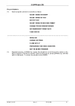
Страница 19: ...RESET CHANGE PRICE OR INHIBIT DRINKS SET INGREDIENT THROW RATE TANK STATUS INITIALISE CHANGE SETTINGS FLUSH SET UP PRESS DRINK FOR FIXED COUNTERS QUIT ENGINEER PROGRAM 15 Repeated pressing of PROG key causes the program to scroll through the options in the above sequence Therefore a specific option is accessed by pressing PROG key until that option is displayed To access any program press ENTER ...

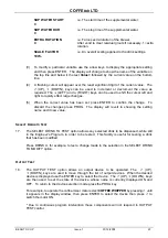
Страница 20: ... step through the remaining variables that control the operation of this selection The following displays will be visible in turn WATER 1 DURATION 75 i e The valve time for the first delivery 7 5 seconds WATER 2 DELAY 0 i e The delay between the first and second deliveries WATER 2 DURATION 0 i e The valve time for the second delivery 0 seconds WHIPPER DELAY 0 i e The delay time which controls the ...

Страница 21: ...ENTER to confirm the change To discard the changes press PROG The display will revert to showing the setting name and it new value SELECT DRINK TO TEST 17 The SELECT DRINK TO TEST option allows any selected drink to be dispensed while still in the Engineer s Program in order to be tested This facility is useful for testing a drink that has been modified Press DRINK A for example to test a change m...

Страница 22: ... press ENTER otherwise press UP and the display will show DRINK A INHIBITED 5 To set DRINK A INHIBITED press ENTER 6 To set for a Jug option press ENTER Jug option is set to allow button to be programmed as Jug function but will only operate when either an internal switch or external key switch is operated 7 Once a setting has been made by pressing ENTER the program exits from the CHANGE PRICE OF ...

Страница 23: ...ill show PROBE IS WET 90 C ADC 380 0 0 The value 380 is a number corresponding to the temperature setting The value 0 0 is the element status 2 Press PROG to exit from the TANK STATUS option and access the next Engineer s Program option INITIALISE 23 The INITIALISE option allows the engineer to initialise the machine 1 Press ENTER The display will show ARE YOU SURE ENTER Y MODE N 2 Press ENTER to ...

Страница 24: ...setting or press ESC to leave the original setting 6 Press À DOWN to access the next setting OUT OF SERVICE and repeat sub paras 3 to 6 Continue in this manner until all required settings have been altered 7 Press prog to exit from the CHANGE SETTINGS option and access the next Engineer s Program option DRY VEND FLAG 0 Enables product only operation 0 Water On 1 Water Off CUP BOOST 5 Allows increa...

Страница 25: ... CREDIT DEVICE Free Selects cash system 0 No Cash system 1 Digicard system 2 Reserved for future use 3 G13 coin acceptor No cash system 0 is the default setting following INITIALISE CREDIT LOCK 0 Disables all free drink facilities 0 Credit Lock disabled default setting 1 Credit Lock active When Credit Lock is set to 1 Credit Device and Credit Lock settings are not displayed Additionally Select Dri...

Страница 26: ... DRINK FOR FIXED COUNTERS option allows the engineer to view the resettable vend counters associated with a selected drink 1 Press the drink selection key on the keypad 2 Press prog to exit from the PRESS DRINK FOR FIXED COUNTERS option and access the next Engineer s Program option Quit Engineer Program 27 Press ENTER ...

Страница 27: ...hine Any procedure which is found to be impracticable inadequate or inaccurate should be reported to the Management for further investigation 3 The requirements of proper hygiene in respect of food products must be ensured at every level of contact with the beverage machine and the ingredients associated with it 4 In compliance with current regulations the materials used in the manufacture of the ...

Страница 28: ... for indoor use in an environment with an ambient temperature range of between 0 C and 40 C The machine should be located close to the appropriate electrical and water services with a minimum of 100mm 4in clearance between the rear of the cabinet and the wall to allow adequate ventilation and if in a corner location not closer to the right hand wall than 400mm 16in to accommodate opening of the do...

Страница 29: ...ated close to the appropriate electrical and water services with a minimum of 100mm 4in clearance between the rear of the cabinet and the wall to allow adequate ventilation and if in a corner location not closer to the right hand wall than 400mm 16in to accommodate opening of the door The unit should not be situated in an area where a water jet could be used Levelling 6 The machine should be level...

Страница 30: ... to the flexible hose 9 The outlet should be fitted with BSP connections and must be positioned within 1 5m of the machine to ensure correct fitting of the hose If possible the outlet should be located behind the machine to prevent misuse 10 Before connecting the machine hose to the mains outlet flush the system via the stopcock to remove any impurities that may have accumulated in the mains suppl...

Страница 31: ... with more cores than required 13 Do not attempt to connect more than one heater to a 230V 10A or 16A single phase supply The mains cable must be connected to the supply via a safety isolator switch preferably located behind the machine Ensure that the supply to the isolator switch is isolated before making the connections Ensure that the supply to the beverage machine is isolated before making an...

Страница 32: ...ion from a 230V 10A 15A supply are as follows LIVE BROWN NEUTRAL BLUE EARTH GREEN YELLOW Important Where a beverage machine is to be connected to a 13A domestic socket outlet a 3 core power cable capable of carrying a minimum current of 13A Part No 54416 must be used This cable is fitted as standard ...

Страница 33: ...ons which have been removed 4 Remove the solenoid operated valves and the thermostat probe from the tank 5 Check the heater element for signs of deterioration Replace if necessary 6 Descale the tank in the approved manner 7 After descaling flush the tank thoroughly with cold water refit the solenoid operated valves and thermostat probe and install and reconnect the tank to the machine 8 Restore th...

Страница 34: ...ce of hygiene and regular cleaning is fully appreciated by the Operator 20 With the water and electrical supplies connected to the machine proceed as follows 1 Set the On Off switch on the machine to OFF 2 Isolate the electrical supply from the machine 3 Open the cabinet door and locate the waste tray 4 Ensure that the overflow pipes are not trapped 5 Restore the electrical supply to the machine 6...

Страница 35: ...al supply from the machine 15 Check all hose connections for leaks 16 Clean the interior and exterior of the cabinet 17 Restore the electrical supply to the machine 18 Set the On Off switch on the machine to ON 19 Operate the machine through the complete range of dispense operations and check that each one is correct ...

Страница 36: ...lle 4 Remove the coffee grouts bucket Empty the contents of the bucket and wash and dry it 5 Disconnect the tube connecting the coffee brewer to the mixing bowl by pulling the black right angled fitting A away from the brewer itself Remove the coffee brewer safety cover and lift the lower carriage locking lever B to the vertical unlocked position Remove the carriage assembly by pulling it gently t...

Страница 37: ...wards the front of the machine 8 Wash and dry the carriage and brew chamber assembly Check the filter belt for signs of wear or damage and if necessary replace 9 Disconnect the pipes from the mixing bowls and dispense head Remove the mixing bowls tubes and dispense nozzles and also the whipper paddle and whipper base Wash and dry these items 10 Wash and dry the dispense area ...

Страница 38: ...s electrical supply to the machine and set the On Off switch on the machine to ON Flushing 23 A flush self clean cycle may be initiated by means of the dedicated flush switch Green Button located on the inside of the machines door or alternatively via the Operators program All that is required to start a flush cycle using the dedicated flush button is to momentarily press the green button Once sta...

Страница 39: ...CUR IF EXCESSIVE VOLUMES OF WATER ARE USED IN THE CLEANING PROCESS WHIPPER AND MIXING BOWL ASSEMBLY 3 Set the on off switch on the machine to off and isolate the mains electrical supply from the machine Unlock and open the cabinet door 4 Rotate the canister nozzles then remove the ingredient canisters Wipe clean the exterior surfaces of the canister assembly and dry thoroughly 5 Disconnect the pip...

Страница 40: ...Procedure 26 1 Open door of machine with key provided 2 Turn ingredient chutes to ensure that product is not trailed over the counter 3 Lift out the product canister Remove lid of canister and fill with correct ingredients to within 3cm of top of canister Do not overfill canister or compress the product in canister 4 Wipe the exterior of the canister with a clean damp cloth using the recommended c...

Страница 41: ... temperature incorrectly set d Excessive scaling in heater tank e Solid state relay fault f Low cut out in program incorrectly set g Temperature probe wet a Jammed motor b Power Supply failure safety trip a Power Supply failure a Check motors b Replace MPU Board c Reset power a Replace keypad b Reconnect c Replace MPU Board a Check and replace b Reset trip c Check desired temperature setting d Che...

Страница 42: ... incorrectly positioned a Dispense pipes incorrectly fitted to dispense head b Mixing bowls incorrectly fitted c Whipper seals missing d Overflow pipe incorrectly fitted a Display connector loose a Thermal cut out tripped b Heater fuse blown c Incorrect temperature setting a Check water pressure b Check inlet valve c Replace MPU Board a Reset desired temperature setting b Replace probe c Replace M...

Страница 43: ...COFFEtek LTD BEAN TO CUP Issue 1 01 12 2005 42 Section 4 Exploded Parts Diagram ...

Страница 44: ... wittern 88734_btc_but_6 dgn 27 01 2009 11 51 10 ...

Страница 45: ......

Страница 46: ......

Страница 47: ......

Отзывы: