O P E R A T I N G M A N U A L
8 0 0 . 7 4 9 . 2 7 6 1
w w w . c o a c h c o m m . c o m
6
2b. Connect a Cat 5 cable to the X-NET IN port on the Antenna.
2c. Connect the other end of the Cat 5 cable to the FIELD ANTENNA port on the Press Box Rack Unit’s rear panel.
2d. If using a second field Antenna, confirm the short Cat 5 cable is properly connected between the first Antenna’s RT
LOOP port and the second Antenna’s X-NET IN port.
Note:
If applicable, a third Antenna for booth wireless can be connected as outlined in the diagram below.
CAUTION:
Secure and protect any cords to prevent walkway hazards and potential contact with moisture.
3. Power on the Control Unit.
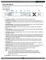
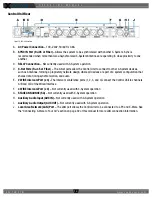
3a. Power ON the CU via the power switch on its front panel.
3b Use CU navigational controls to select
Home
or
Away
and press the Enter button.
Important:
No RF transmission will occur until the Home/Away status is selected. Failure to set
this status properly may result in RF interference if and when the opposing team
is also using an X-System. It is important to coordinate with opponents to ensure
optimal performance for both teams.
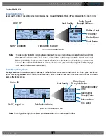
3c. Wait until the CU displays the following message: “CCF Loaded” along with a configuration file summary. Once the
message times out, the home screen will display on the front of the CU.
Figure 3: Press Box Rack Unit Connections to Antennas
First Field Antenna
Second Field Antenna
Optional Booth Antenna
Pressbox
Rack Unit
Figure 4: CU Navigation Buttons
Figure 5: Sample CCF Loaded Screen
Содержание X2
Страница 1: ...Operating Manual X2 Package ...


