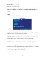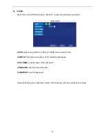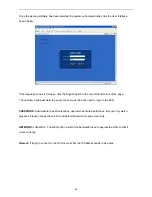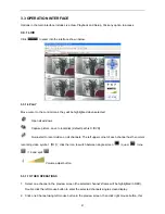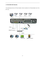
2. THE DEFINITION OF BUTTONS AND CONNECTORS ON THE REAR PANEL
The example below shows an 8 Channel System, but the connections for a 4 Channel System are exactly
the same except there are fewer Video Inputs and Alarm Inputs.
Connectors on Rear Panel
Item
Physical Connector
Connector Description
1
POWER input
DC 19V/3A
2
Video output
Two video outputs for connecting TV or monitor (BNC)
3
Video input
For connecting analog video signal input (BNC)
4
Audio Input
For connecting audio signal
Alarm Input
I/O alarm input, 4 for 4CH DVR and 8 for 8CH DVR
Alarm Output
I/O output for alarm
RS485
RS 485 for connecting PTZ
RS232
For connecting PC
5
+12V
Power supply for DC relay and the current is 100MA
(
Please ensure short circuit can not happen
)
6
Network
For connecting Ethernet
7
VGA output
For connecting to a standard LCD Monitor
8
USB2.0
Copy video record via USB2.0
9
Audio output
For connecting audio output
10
Fan
Please check the fan occasionally as part of maintenance.
36


