Operating Instructions
AceroDURO
CNC-STEP GmbH & Co. KG ▪ Siemensstrasse 13-15 ▪ 47608 Geldern ▪ Germany
Page 40
Support: +49 (0)2831/91021-50 15/05/2020
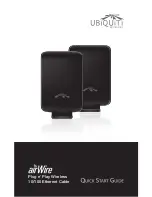
Fig. 10c: X-Carriage
1 Reference Switch X-Axis
2 Switch Activator (Magnet) of the X axis
The reference switch (Fig. 10c /1) reacts to the magnetic field of
the magnet arriving during a reference trip (Fig. 10c /2). If the
magnet is close enough, the internal reed sensor of the switch
responds.
The reference switch works as a Normally Closed, i.e. the signal
circuit is closed when triggered by the magnet.
NOTE:
If the position of the magnet holder of the X-axis is changed, settings must be taken
into account in the control software under the topic “working space”.
4 . 3 . 4
Tool holder
Fig. 11: Tool holder 43H7
On the tool holder of the Z-axis (Fig. 11/1) some of the most
important additional available tools are attached (see Appendix
"Accessories").
1
2
1