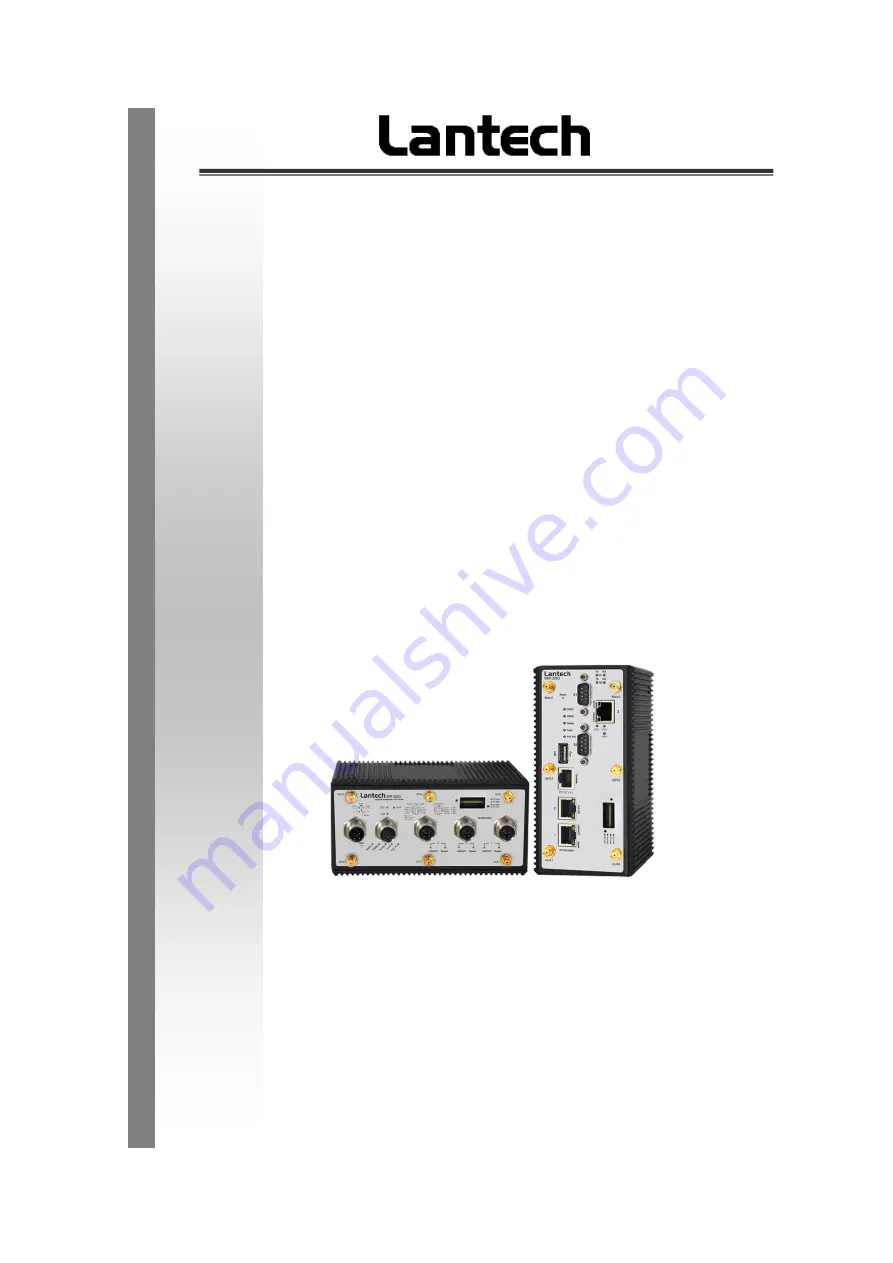
background image


IWMR-3003 

Industrial Multifunction VPN Router w/up to 2x WiFi 11ac + up to 2 

LTE 4G + 2/4 serial ports + 3 Gigabit Ethernet Switch


IMR-3003 

Industrial Multifunction VPN Router w/up to 2 LTE 4G + 2/4 serial 

ports + 3 Gigabit Ethernet Switch


IWAP-3003 


Industrial Multifunction VPN Router w/up to 2x WiFi 11ac + 2/4 

serial ports + 3 Gigabit Ethernet Switch


        User Manual (Hardware) 


Dec. 2021 

Summary of Contents for IMR-3003

Page 1: ...serial ports 3 Gigabit Ethernet Switch IMR 3003 Industrial Multifunction VPN Router w up to 2 LTE 4G 2 4 serial ports 3 Gigabit Ethernet Switch IWAP 3003 Industrial Multifunction VPN Router w up to 2...

Page 2: ...y an STP network cable in demanding electrical environments Examples of demanding indoor environments are where the network cable is located in parallel with electrical mains supply cables or where la...

Page 3: ...n consent of Lantech Communications Global Inc Products offered may contain software which is proprietary to Lantech Communications Global Inc The offer or supply of these products and services does n...

Page 4: ...t occur in a particular installation If this equipment does cause harmful interference to radio or television reception which can be determined by turning the equipment off and on the user is encourag...

Page 5: ...nting 16 2 3 Wall Mount Plate Mounting 18 2 4 Wiring the Power Inputs 20 2 4 1 Steps to Insert the Power Wire 20 2 4 2 Grounding 21 2 5 Wiring the Fault Alarm Contact 22 2 6 Cabling 23 2 7 SIM 23 2 8...

Page 6: ...4 Console Management 34 4 1 Connecting to the Console Port 34 4 1 1 RJ45 Models 34 4 1 2 M12 models 35 4 2 Login in the Console Interface 35...

Page 7: ...n industrial multi function VPN routers In this paragraph it will describe the Industrial multi function VPN router s hardware spec port cabling information and wiring installation 1 1 Physical Dimens...

Page 8: ...4 82 W x 172 D x 152 H mm WV model IWMR 3003 M12 model Metal case IP 43 74 W x 122 D X 152 H mm...

Page 9: ...5 IMR 3003 RJ 45 model Metal case IP 30 74 W x 114 D x 152 H mm 12V 24V model 82 W x 172 D x 152 H mm WV model...

Page 10: ...6 IMR 3003 M12 model Metal case IP 43 74 W x 122 D X 152 H mm IWAP 3003 RJ 45 model Metal case IP 30 74 W x 114 D x 152 H mm 12V 24V model...

Page 11: ...7 82 W x 172 D x 152 H mm WV model IWAP 3003 M12 model Metal case IP 43 74 W x 122 D X 152 H mm...

Page 12: ...t access to hazardous parts e g electrical conductors moving parts and the ingress of solid foreign objects Level Object size protected against Effective against 0 No protection against contact and in...

Page 13: ...est duration 10 minutes Water equivalent to 3 mm rainfall per minute 3 Spraying water Water falling as a spray at any angle up to 60 from the vertical shall have no harmful effect Test duration 5 minu...

Page 14: ...f at least 1 m measured at bottom of device and at least 15 cm measured at top of device 8 Immersion beyond 1 m The equipment is suitable for continuous immersion in water under conditions which shall...

Page 15: ...11 1 3 Front Panel IWMR 3003 RJ 45 model IWMR 3003 M12 model...

Page 16: ...12 IMR 3003 RJ 45 model IMR 3003 M12 model...

Page 17: ...13 IWAP 3003 RJ 45 model IWAP 3003 M12 model...

Page 18: ...tive Off Power 2 is inactive Fault Red On Power or port failure Off No failure LTE Green On LTE is active Off LTE is inactive GPS Green On GPS OK Blinking Searching GPS Signal WLAN Green On WLAN is ac...

Page 19: ...Only on RJ 45 models Green On The port is transmitting packets Off The port is not transmitting packets S1 S4 RX Only on RJ 45 models Green On The port is receiving packets Off The port is not receiv...

Page 20: ...D lights 5 Prepare the twisted pair straight through Category 5 cable for Ethernet connection 6 Insert one side of RJ 45 cable category 5 into the Industrial device Ethernet port RJ 45 port and anothe...

Page 21: ...17 First insert the top of DIN Rail into the track Then lightly push the DIN Rail into the track...

Page 22: ...emove the DIN Rail from the industrial device loose the screws to remove the DIN Rail 2 Place the wall mount plate on the rear panel of the industrial device 3 Use the screws to screw the wall mount p...

Page 23: ...19...

Page 24: ...1 Steps to Insert the Power Wire Please follow the steps below to insert the power wire 1 Insert DC power wires into the contacts 1 and 5 with negative electrode of power and 2 and 6 with positive el...

Page 25: ...enting the wires from loosing NOTE The wire gauge for the terminal block should be in the range between 12 24 AWG 2 4 2 Grounding The chassis is grounded via a separate ground nut M3 Use toothed locki...

Page 26: ...e device will detect the fault status of the power failure or port link failure available for managed model and then forms an open circuit The following illustration shows an application example for w...

Page 27: ...8 ft long 2 7 SIM 1 Turn off power of the device 2 Use a screwdriver to loosen the screws and remove the SIM card cover 3 Insert one or two 3G 4G SIM cards into the SIM card slots in the correct orien...

Page 28: ...24 Located on the bottom of the SIM card slot For LTE2 slot Insert the SIM card into the SIM card slot with the gold contacts facing up Located on the bottom of the SIM card slot...

Page 29: ...25 2 8 Serial Ports Connect the DB9 connector with RS232 RS422 RS485 cable with the following PIN assignment PIN Assignment of RS232 PIN Assignment of RS 422 PIN Assignment of RS 485...

Page 30: ...D Indicators section for indication of LED lights 5 Prepare the straight through X Code M12 cable for Ethernet connection 6 Insert one side of X Code M12 cable into the Industrial device Ethernet port...

Page 31: ...plate on the side panel of the industrial device 2 Use the screws to screw the wall mount plate on the industrial device 3 Use the hook holes at the corners of the wall mount plate to hang the indust...

Page 32: ...age can be from 9 36VDC WV model The power input voltage can be from 16 8 137 5VDC Dual Power Input Pin assignment of Power input The power input can be supported redundantly The supply voltage is ele...

Page 33: ...ctor with 6 pins TYCO reference 8 968970 1 Blue Code A Ignition sensing After trigger the Ignition sensing the device will power on The ignition pin must connect to driver power main key with voltage...

Page 34: ...a a separate ground nut M3 Use toothed locking washers for a good electrical connection 3 4 Wiring the Reset or USB Pin assignment of Reset Console USB Connect the pin1 pin7 for 10 seconds and the dev...

Page 35: ...te The USB port is USB 2 0 speed not USB 3 0 3 5 Cabling Connect the M12 connector with RJ 45 data cable ports are not used shall be caped that comes with the package to insulate the surrounding Pin a...

Page 36: ...rt one or two 3G 4G SIM cards into the SIM card slots in the correct orientation and located on the bottom of the SIM card slot 9 Turn on power of the device 10 Reattach the cover For LTE LTE1 slot In...

Page 37: ...33 For LTE2 slot Insert the SIM card into the SIM card slot with the gold contacts facing up Located on the bottom of the SIM card slot...

Page 38: ...nnector Attach the end of RS 232 connector to PC or terminal and the other end of RJ 45 connector to the console port of the device The connected terminal or PC must support the terminal emulation pro...

Page 39: ...the switch The connected terminal or PC must support the terminal emulation program 4 2 Login in the Console Interface When the connection between Device and PC is ready turn on the PC and run a term...

Page 40: ...pt appears Key in admin default value for both User name and Password use Enter key to device then press Enter and the Main Menu of console management appears Please see below figure for login screen...

Reviews: