


EZBells
J
Carillon Operating Manual
34
Installing the EZ Bells Carillon
Before you install or hookup the tower speakers, you can simply plug in the system, configure it
(see page 8), and play it through the built-in monitor speaker. Familiarity with the carillon
operation, before finishing the installation, will make the first test (below) more satisfying.
There are several options that are available concerning the hookup and operation of the EZ Bells
Carillon System. The remainder of the manual is dedicated to the
RECOMMENDED
installation
and connection procedures. There are other options that are addressed in the enclosed “RMX
Series Amplifier” manual. There is also information on the rear of the amplifier. As always, if you
have questions concerning installation or operation, please call our customer service line, 1-800-
432-3977.
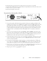
EZ Bells Carillon Connection Details
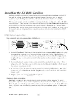
Rear panel with built-in tower amplifier – EZ Bells—A
1.
Connect the speaker cable from the tower speakers to the
Tower Speaker
binding posts. Strip
wire insulation to expose 3/8 of an inch of copper. Loosen the binding posts by turning
counter-clockwise. Insert the wires into the openings at the bottom of the binding posts and
retighten. Under no circumstances should either speaker wire be connected to a ground or
conduit.
2.
Connect the remote receiver to the control unit with the supplied 6 ft. cable with a 1/8 in.
plug on the end. Push the connector all the way into the
Remote Control
jack. Fully extend
the antenna and orient vertically.
3.
If connection to the PA system is desired, purchase a connecting cable with a ¼” TRS audio
jack to insert into the
Line Out – Inside Amplifier
jack on the control unit (below the tower
output plug).
4.
Plug the power cord into a grounded AC receptacle.
Operation – Built-in Amplifier
First Test
- Set the front panel monitor level control and the rear panel master level control
(screwdriver adjustment on the built-in amplifier is to the left of the heat sink) to their midpoints.
Turn the system on with the power switch on the rear panel of the system control unit. When the
display shows the time and date (the Standby mode), press
1
then
Enter
. A swinging bell should
play.


