background image

VTX-WM1 Installation Guide v1.1

6

















































































































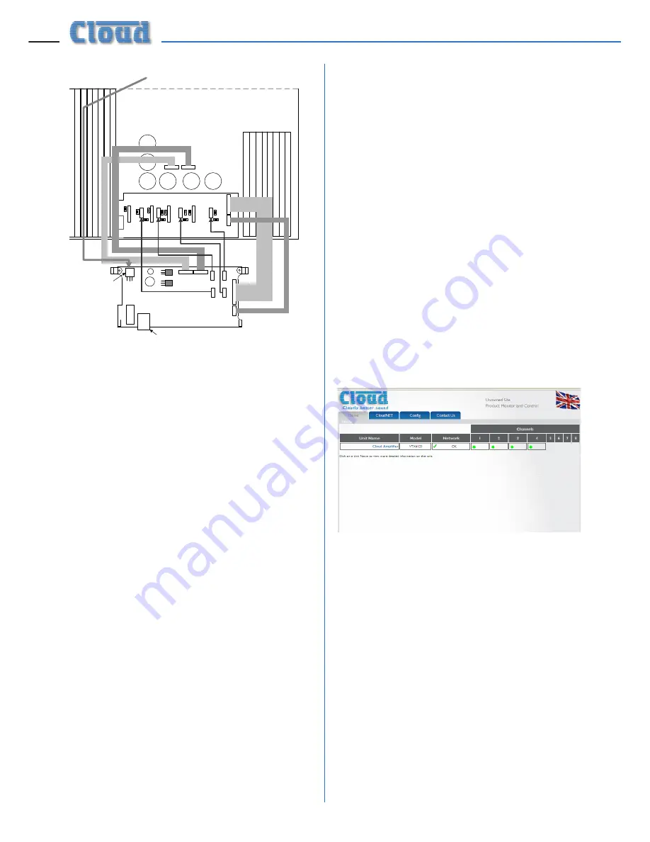
8.  The VTX-WM1 card can now be fitted 

in place; the two rear supports should 

engage with the edge of the heatsinks, 
and the RJ-45 Ethernet connector should 

protrude through the rear panel slot. 
The two previously empty holes in the 
amplifier rear panel should align with the 

tapped holes in the card’s rear brackets; 

secure the card using the two screws 
supplied.

9.  Locate the spare internal AC cable coming 

from the amplifier power transformer. This 
will have one red and two yellow wires 
and will terminate in a 3-pin Molex plug. 
It may be cable-tied; if so, cut the tie. Plug 

the connector into the large 3-pin Molex 

header on the front left corner of the 
VTX-WM1 card.

10.  Fix the new rear plate (supplied) over the 

card slot using the two screws removed 
in Step 3, so that the RJ-45 connector is 
engaged with the square hole in the plate. 
Replace the top cover.

11.  We recommend that the amplifier is 

connected to a computer at this stage 
to check communications. Connect the 

VTX-WM1 card’s Ethernet port to the 
network port on a computer using a 
standard CAT5 (or CAT5-e) network 
cable, terminated with RJ45 plugs. Either 
a “straight” or a “crossed” cable may be 

used, as the VTX-WM1 auto-detects the 

data lines. Power the amplifier on; it is 
not necessary at this stage to connect 
any audio inputs or outputs. Turn the 
computer on and check that it has a static 

IP address of the form 192.168.0.xxx, 
where xxx can be any value between  
1 and 254 except 127. Launch the Internet 
browser normally used (e.g., Microsoft 
Internet Explorer, Mozilla Firefox, Safari, 

etc.)

12.  Type the card’s default IP address - 

192.168.0.127 - into the URL field of the 

browser, and the screen shown below 
should appear:


The amplifier type listed in the 

Model


column should be that of the amplifier 
in use. This confirms that the data 
communications section of the card is 
operating correctly. The card’s IP address 
can be changed subsequently, and this 

procedure is discussed in “Entering site 
and amplifier information” on page 8.

13.  Close the browser application. The 

amplifier may now be disconnected from 

the computer and powered off. Reinstall in 
the rack and reconnect all rear cables.

14.  Repeat the above procedure for the 

remaining VTX amplifiers.

POWER

CONNECTOR

Содержание VTX-WM1

Страница 1: ...VTX WM1 Web Monitor Card Installation and User Manual...

Страница 2: ...VTX WM1 Installation Guide v1 1 2...

Страница 3: ...8 Server allocation 8 Entering site and amplifier information 8 Amplifier data using the GUI 10 Amplifier Status 11 Monitors 11 Configuration 11 Network status 11 Site Configuration 12 Port No 12 Logi...

Страница 4: ...he installation how to use the GUI how to interconnect multiple amplifiers to form a network NOTE a short video giving an overview of the installation and configuration of the VTX WM1 is available on...

Страница 5: ...H2 0V CH3 0V CH4 ON OFF ON OFF ON OFF BRIDGE 1 2 ON OFF BRIDGE 3 4 4 OHMS MIN BRIDGE 3 4 BRIDGE 1 2 POWER 40 60Hz 10 4 On the amplifier s upper rear PCB RemoteVol PCB PC331012 locate the jumpers J109...

Страница 6: ...et port to the network port on a computer using a standard CAT5 or CAT5 e network cable terminated with RJ45 plugs Either a straight or a crossed cable may be used as theVTX WM1 auto detects the data...

Страница 7: ...s VTX WM1 card should be connected to a port on the switch using a standard CAT 5 network cable The switch should then be connected into the building s IT infrastructure at the nearest convenient poin...

Страница 8: ...are to be monitored one but only one amplifier may retain this default address again subject to its availability Server allocation Once all the amplifiers have been configured it will be possible to...

Страница 9: ...lick Apply to close the dialogue box 9 Click Apply on the Config page to confirm the data entered Click the blue Cloud Amplifier button in the left hand pane only one amplifier will be listed at prese...

Страница 10: ...amplifier retains Server status because the browser is still using its IP address 17 The additional amplifier will have the default IP address this will need to be changed Click the Config tab and sel...

Страница 11: ...dge mode rear panel switch setting Input linking rear panel switch setting Current level control rear panel rotary control setting Current external level control RL 1 remote control plate setting if f...

Страница 12: ...is opened Request login is active by default After logging in with the password remember to log out by clicking the Log out button at the top of the amplifier list on this page The Amplifier Status an...

Страница 13: ...om the drop down list under Channel If any channels are in Bridge Mode select the lower numbered channel of the pair Select the frequency to be used for the test from the drop down list under Frequenc...

Страница 14: ...ect the date on which the next test is to be run by clicking on it The months can be scrolled through with the and buttons at the top Next select the time at which the test is to be run using the Hour...

Страница 15: ...J814 Force defaults Restores all factory default settings Off J815 Force config Disables password protection Off J816 Force IP 192 168 0 126 Fixes IP address Off J817 Force bootload Only required for...

Страница 16: ...n 1 3 octave steps Sensitivity 1 to 100 Ohm detection Signal detector Sensitivity 30 dBu to 10 dBu 20 Hz to 20 kHz Networking DHCP Not supported Data rates 10 BaseT or 100 Base T automatic selection C...

Отзывы: