VTX-WM1 Installation Guide v1.1
11
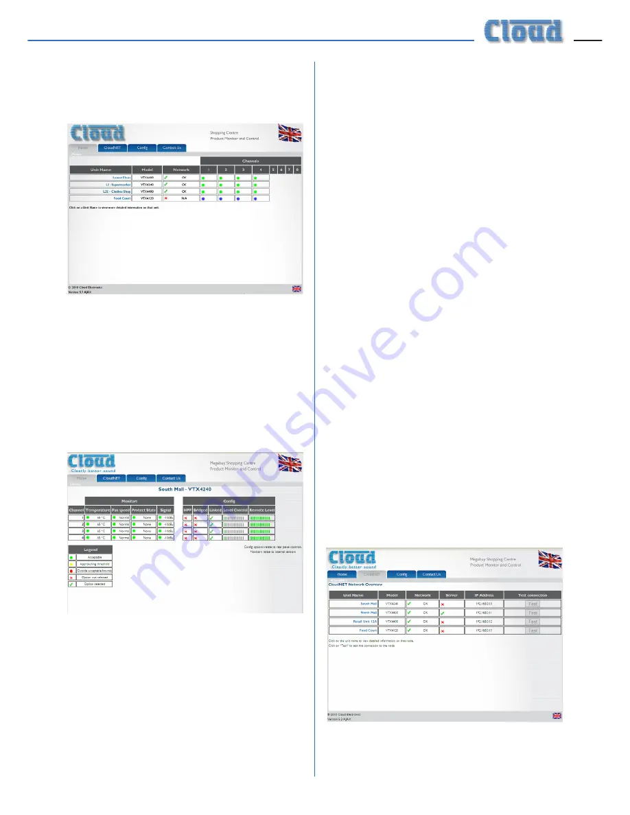
Model type is confirmed, and any Network
faults. If an amplifier cannot be found on the
network, a red cross appears in the Network
column, as shown below:
A green indicator in the
Channels
columns
confirms that each channel of each amplifier is
operating normally.
Amplifier Status
Each amplifier’s performance and settings may
be checked in greater detail by clicking on its
name in the
Unit Name
column. This gives a
display as below:
Each channel of the amplifier reports its status
as follows:
Monitors:
•
Internal heatsink temperature
•
Fan speed
•
Clip limiter circuitry status
•
Input signal level (in dBu)
Configuration:
•
High-pass filter – rear panel switch setting
•
Bridge mode – rear panel switch setting
•
Input linking – rear panel switch setting
•
Current level control – rear panel rotary
control setting
•
Current external level control – RL-1
remote control plate setting (if fitted)
Colours are used to indicate amplifier
conditions:
•
Green:
Normal operation
•
Yellow:
Becoming marginal
•
Red:
Outside acceptable limits
In the
Config
area, a green tick indicates that
a function activated by one of the rear panel
switches is ON, a red cross indicates that it is
OFF. The settings of the local and remote level
controls are shown as horizontal bargraphs,
with the “segments” changing from grey to
green as the level controls are advanced.
This page can be closed by clicking on any other
tab, or your browser’s “Back” button.
Network status
Clicking the
CloudNET
tab opens the
Network Overview page:
The CloudNET page lists all amplifiers on the
system, together with confirmation of each
Содержание VTX-WM1
Страница 1: ...VTX WM1 Web Monitor Card Installation and User Manual...
Страница 2: ...VTX WM1 Installation Guide v1 1 2...


