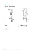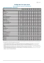
Configuration for 2-pipe system
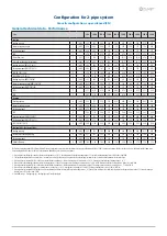
Acoustic configuration: super-silenced (EN)
General technical data - Construction
Size
90.4
100.4
110.4
120.4
140.4
160.4
180.4
200.4
220.4
240.4
Compressor
Type of compressors
-
Scroll
Scroll
Scroll
Scroll
Scroll
Scroll
Scroll
Scroll
Scroll
Scroll
Refrigerant
[kg]
47
47
47
57
64
65
79
79
81
95
No. of compressors
No
4
4
4
4
4
4
4
4
4
4
Rated power (C1)
[HP]
45
50
55
60
70
80
90
100
100
120
Rated power (C2)
[HP]
45
50
55
60
70
80
90
100
120
120
Std Capacity control steps
No
6
6
6
4
6
4
6
6
5
4
Oil charge (C1)
[l]
10
11
13
13
13
13
13
13
13
13
Oil charge (C2)
[l]
10
11
13
13
13
13
13
13
13
13
Refrigerant charge (C1)
1
[kg]
47
47
47
57
64
65
79
79
81
95
Refrigerant charge (C2)
1
[kg]
47
47
47
57
64
65
79
79
88
95
Refrigeration circuits
No
2
2
2
2
2
2
2
2
2
2
Internal exchanger
Type of cold user side exchanger
2
-
PHE
PHE
PHE
PHE
PHE
PHE
PHE
PHE
PHE
PHE
Type of hot user side exchanger
2
-
PHE
PHE
PHE
PHE
PHE
PHE
PHE
PHE
PHE
PHE
Cold user side exchanger water content
[l]
22
22
24
29
32
37
49
49
62
62
Hot user side exchanger water content
[l]
14,4
14,4
18,0
18,0
25,2
25,2
43,2
43,2
54,0
54,0
User side minimum system water content
3
[l]
1667
1719
2050
2383
2652
3018
3234
3234
4313
4517
Recovery side minimum system water content
3
[l]
1983
2130
2527
2887
3199
3596
3812
4097
5072
5320
External Section Fans
Type of fans
4
-
AX
AX
AX
AX
AX
AX
AX
AX
AX
AX
Number of fans
No
6
6
6
6
8
8
10
10
10
10
Type of motor
5
-
AC/P
AC/P
AC/P
AC/P
AC/P
AC/P
AC/P
AC/P
AC/P
AC/P
Standard airflow
[l/s]
30588
30588
29943
29570
40784
39924
50870
49776
49467
49159
Connections
User side water fittings
-
4”
4”
4”
4”
4”
5”
5”
5”
5”
5”
Recovery side water fittings
-
4”
4”
4”
4”
4”
5”
5”
5”
5”
5”
Power supply
Standard power supply
V
400/3~/50 400/3~/50 400/3~/50 400/3~/50 400/3~/50 400/3~/50 400/3~/50 400/3~/50 400/3~/50 400/3~/50
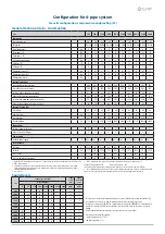
Electrical data
FLA - Total
A
205,2
216,5
233,3
262,1
299,3
328,3
387,9
416,9
457,1
497,3
FLI - Total
kW
117,7
128,6
138,2
155,8
180,7
201,9
231,2
252,4
275,8
299,2
M.I.C. - Value
6
A
455,6
466,9
483,7
512,5
619,2
648,2
657,6
686,6
726,8
767,0
M.I.C. - with soft start accessory
6
A
317,8
329,1
345,9
374,7
447,2
476,2
657,6
686,6
726,8
767,0
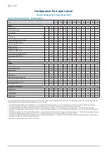
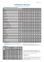
Sound levels
Size
Sound power level (dB)
Sound
power
level
Sound
pressure
level
Octave band (Hz)
63
125
250
500
1000
2000
4000
8000
dB(A)
dB(A)
90.4
87
84
84
82
82
79
65
56
86
66
100.4
87
84
84
82
82
79
65
56
86
66
110.4
87
84
84
82
82
79
65
56
86
66
120.4
88
85
85
83
83
80
66
57
86
66
140.4
88
85
85
83
83
80
66
57
86
66
160.4
89
86
86
84
84
81
67
58
87
67
180.4
96
92
91
88
84
79
73
67
90
69
200.4
96
92
91
88
84
79
73
67
90
69
220.4
97
93
92
89
85
80
74
68
90
69
240.4
97
93
92
89
85
80
74
68
90
70
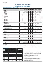
The sound levels refer to standard unit with Axitop (no accessories) at full load, in test nominal conditions. The
sound pressure level refers to 1 m. from the standard unit outer surface operating in open field.
Measures are according to UNI EN ISO 9614-2 regulations, with respect to the EUROVENT 8/1 certification, which
provides for a tolerance of 3 dB(A) on the sound power level, which is the only acoustic data to be considered
binding.
If unit is set without Axitop, the sound power level presents an increase up to 3 dB(A).
Data referred to the following conditions.
- internal exchanger water = 12/7 °C
- Ambient temperature = 35 °C
The indicated sound levels are only valid within the operating field of the standard unit at full load as indicated
in the ‘Operating range - cooling ‘ graph in the “Super-silenced EN” configuration. With outdoor air temperatures
the unit operates at full load automatically increasing the airflow and taking the same sound levels of the
“Soundproofed Compressors SC” configuration.
1. Indicative values for standard units with po/-10% variation. The actual data are indicated on the label of the unit.
2. PHE = Plate exchanger
3. The minimum system water content calculated value does not consider the internal exchanger water content. With
outdoor air low temperature applications or low medium requested loads, the minimum installation water volume is
obtained doubling the indicated value
4. AX = axial fan
5. AC/P = asynchronous three-phase external rotor motor with phase cutting speed automatic control
Unbalance between phase max 2 % Voltage variation: max +/- 10%
Electrical data refer to standard units; according to the installed accessories, the data can suffer some variations.
6. M.I.C.=Maximum unit starting current. The M.I.C. value is obtained adding the max. compressor starting current of the
highest size to the power input at max. admissible conditions (F.L.A.) of the remaining electric components.
Содержание WSAN-XSC3 MF 200.4
Страница 20: ...20 WSAN XSC3 MF 90 4 240 4 M02M40N15 01 6 4 Configuration for 2 pipe system ...
Страница 45: ...M02M40N15 01 WSAN XSC3 MF 90 4 240 4 45 8 17 Compressor replacement ...
Страница 46: ...46 WSAN XSC3 MF 90 4 240 4 M02M40N15 01 8 18 Exchanger replacement ...
Страница 47: ...M02M40N15 01 WSAN XSC3 MF 90 4 240 4 47 9 Accessories 9 1 Anti vibration mount support ...
Страница 48: ...48 WSAN XSC3 MF 90 4 240 4 M02M40N15 01 ...

