
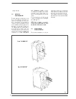


25
2.1
BOILER ROOM
The boiler room should feature all the
characteristics required by standards
governing liquid fuel heating systems.
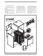
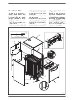
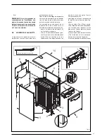
2.2
BOILER ROOM DIMENSIONS
Position the boiler body on the founda-
tion bed, which should be at least 10
cm high. The body should rest on a
surface allowing shifting, possibly by
means of sheet metal.
Leave a clearance between the boiler
and the wall of at least 0.60 m, and
between the top of the casing and the
ceiling of 1 m (0.50 m in the case of
boilers with incorporated D.H.W. tank).
The ceiling height of the boiler room
should be less than 2.5 m.
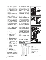
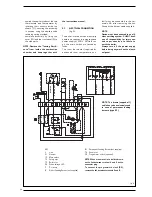
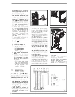
2.3
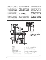
CONNECTING UP SYSTEM
When connecting up the water supply
to the boiler, make sure that the speci-
fications given in fig. 1 are observed.
All connecting unions should be easy
to disconnect by means of tightening
rings. A closed expansion tank system
must be used.
2.3.1
Filling the water system
Before connecting the boiler, thorou-
ghly flush the system to eliminate
scale which could damage t he
appliance.
Filling must be done slowly so as to allow
any air bubbles to be bled off through the
air valves. In closed-circuit heating
systems, the cold water filling pressure
and the pre-charging pressure of the
expansion vessel should be no less than
or equal to the height of the water head
of the installation (e.g. for water head of
5 metres, the vessel pre-charging pres-
sure and installation filling pressure
should be at least 0.5 bar).
2.3.2 Water system
characteristics
Water supplying the heating circuit
must be treated in accordance with
UNI-CTI 8065 standards.
It is absolutely essential to treat water
in the heating system in the following
cases:
– for extensive systems (with high
contents of water);
– frequent addition of water into the
system;
– should it be necessary to empty the
system either partially or totally.
2.4
CONNECTING UP FLUE
The flue is of fundamental importance
for the proper operation of the boiler;
if not installed in compliance with the
standards, starting the boiler will be
difficult and there will be a consequent
formation of soot, condensate and
encrustation.
The flue used to expel combustion pro-
ducts into the atmosphere must meet
the following requirements:
– be constructed with waterproof
materials, and resistant to smoke
temperature and condensate;
– be of adequate mechanical resilien-
ce and of low heat conductivity;
– be perfectly sealed to prevent coo-
ling of the flue itself;
– be as vertical as possible; the termi-
nal section of the flue must be fitted
with a static exhaust device that
ensur es cons t ant and ef f icient
extraction of products generated by
combustion;
– to prevent the wind from creating
pressure zones around the chimney
top greater than the uplift force of
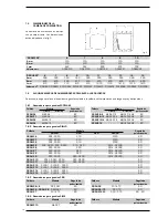
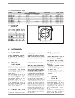
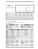
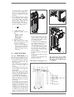
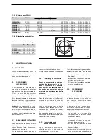
1.6.6 Burner flange
The dimensions of the diesel burner
anchorage flange are given in fig. 4.
2
INSTALLATION
A
B
C
Fig. 4
A
B
C
mm
mm
ø
GG GMP 6
110
150
M8
GG GMP 7÷10
130
170
M8
GG GHP 6-7
130
170
M8
GG GHP 8÷15
160
190
M10
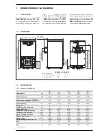
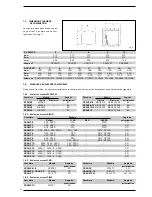
1.6.5 RIELLO gas burners
Boiler
Model
Output (kW)
Electrical
Gas
1°stage
2°stage
data
type
GG GMP 6÷9
GS10
42÷116
–
230V
±
10%
~
50Hz
G20/25 - G30/31
GG GMP 10
FS10
42÷116
–
230V
±
10%
~
50Hz
G20/25 - G30/31
GG GHP 6
GS10
42÷116
–
230V
±
10%
~
50Hz
G20/25 - G30/31
GG GHP 7÷8
BS 3
65÷189
–
230V
±
10%
~
50Hz
G20/25 - G30/31
GG GHP 9÷11
BS 4
110÷246
–
230V
±
10%
~
50Hz
G20/25 - G30/31
GG GHP 8÷15
RS 28
81
163-325
230V
±
10%
~
50Hz
G20/25 - G30/31
GG GHP 8÷15
RS 28/1
163÷349
–
230V
±
10%
~
50Hz
G20/25 - G30/31


