


38
G e o t h e r m a l H e a t i n g a n d C o o l i n g
Tranquility
®
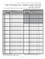
30 Digital (TE) Series IOM - 60Hz HFC-410A
R e v. : 2 9 M a y, 2 0 1 5 J
DXM2 Layout and Connections
P1
Alarm
Relay
Comp
Relay
O
Y1
Y2
W
G
C
R
AL1
24Vdc
EH1
EH2
P6
R
C
Off On
JW3
A
OVR
ESD
C
R
NSB
AL2
JW1
Acc1
Relay
Acc2
Relay
H
COM1
NC1
NO1
COM2
NC2
NO2
P3
CO
RV
RV
LT1
LT1
LT2
LT2
LP
LP
HP
HP
P7
Status
Fault
R
R
CC
CCG
CO
S1
S2
1
12
1
4
e
s
U
yr
ot
c
a
F
(240Vac)
Com
N.O.
Fan Enable
Micro
U1
Off On
P2
COH
COM
AO2
P11
Gnd
T1
P10
T2 T2 T3
T3 T4 T4
T5
P9
T5 T6 T6
A0-1 A0-2
Off On
S3
RV
Relay
CCH
Relay
Test
P5
B-
Gnd
P4
A+ 24V
(240Vac)
Fan Speed
N.O.
N.C.
12V
OUT
Gnd
P8
IN
NC
P12
1 2 3 4
1 2 3 4 5 6 7 8
1 2 3 4 5 6 7 8
Service tool
connection
Communicating
stat connection
Conventional
stat connection
Cabinet
temperature
sensor
(with variable
speed pump)
24V to compressor
second-stage solenoid
for Y2/full
load capacity
Use 4 mounting screws
#6 sheet metal screw
1” long
Configure
modulating valve
or variable
speed pump
V
a
riable
speed pump
Entering
water temp
Leaving
water temp
Leaving
air temp
Electric heat
connection
Factory low
voltage molex
connection for
unit harness
Entering Hot water
T
e
mperature
Compressor Discharge
temperature
ECM Motor
Connection
Test Button
to Speed up
Time Delays
Communications
and HWG
Settings
Water Coil
Low Temp
Limit Setting.
JWT-LT1 jumper
should be clipped
for low temp
(antifreeze)
operation
Accessory
relays refer
to DXM2 AOM
for configuration
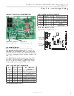
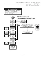
Figure 31: LT1 Limit Setting
Comp
Relay
24Vdc
EH1
EH2
P6
Off On
JW3
c1
ay
c2
ay
CO
RV
RV
LT2
LT2
P7
CC
CCG
CO
S1
S2
12
1
4
Off On
AO2
P11
Gnd
T1
P10
T2 T2 T3
T3 T4 T4
T5
P9
T5 T6 T6
A0-1 A0-2
Off On
S3
RV
Relay
CCH
Relay
1 2 3 4
1 2 3 4 5 6 7 8
1 2 3 4 5 6 7 8
O1 Gnd
DXM2 PCB
JW3-LT1 jumper should be clipped
for low temperature (antifreeze) operation
Low Water Temperature Cutout Selection
The DXM2 control allows the
fi
eld selection of low water
(or water-antifreeze solution) temperature limit by clipping
jumper JW3, which changes the fault cutout temperature
associated with thermistor LT1. Note that the LT1 thermistor
is located on the refrigerant line between the coaxial heat
exchanger and expansion device (TXV). Therefore, LT1 is
sensing refrigerant temperature, not water temperature,
which is a better indication of how water
fl
ow rate/
temperature is a
ff
ecting the refrigeration circuit.
The factory setting for LT1 is for systems using water
(30°F [-1.1°C] refrigerant temperature cutout or fallout). In
low water temperature (extended range) applications with
antifreeze (most ground loops), jumper JW3 should be
clipped as shown in Figure 31 to change the setting to 10°F
[-12.2°C] refrigerant cutout or fallout temperature, a more
suitable temperature when using an antifreeze solution.
All residential units include
water/refrigerant circuit
insulation to prevent internal
condensation, which is
required when operating with
entering water temperatures
below 59°F [15°C].
Figure 32: DXM2 Layout and Connections
Содержание Tranquility 30 TE026
Страница 2: ...This page was intentionally left blank ...


