

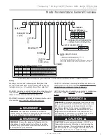


11
c l i m a t e m a s t e r. c o m
Tranquility
®
30 Digital (TE) Series IOM - 60Hz HFC-410A
R e v. : 2 9 M a y, 2 0 1 5 J
The following section will help to guide you through
fl
ushing a
unit with internal
fl
ow control.
Water Pressure Schrader Ports
The pressure ports built in to the unit are provided as a
means of measuring pressure drop through the water-to-
refrigerant heat exchanger. The water pressure ports are
schrader ports smaller than refrigerant schrader ports. They
are the same size as tire schrader ports. A digital pressure
gauge is recommended for taking pressure readings
through these ports. The water
fl
ow through the unit can be
determined by measuring the water pressure at the “water
pressure out” port and subtracting it from the water pressure
at the “water pressure in” port. Comparing the pressure
di
ff
erential to the pressure drop table (wpd)/
fl
ow rate in
Tables 17a through 17e in this manual will determine the
fl
ow
rate through the unit.
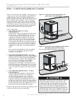
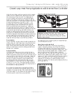
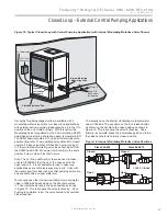
Closed Loop Heat Pump Applications with Internal Flow Controller
Figure 12: Internal Flow Controller
Digital Pressure Gauge
Units with internal
fl
ow control come with a built-in variable
speed pump, an expansion tank,
fl
ushing ports and three-
way valves (used to
fl
ush the unit). The variable speed
pump is controlled by the Communicating DXM2 board
based on the di
ff
erence between the entering and leaving
water temperature (
Δ
T). For operation outside of the normal
entering water temperature range (50° or 60°F - 110°F
for cooling, 30°F-70°F for heating) the DXM2 controller
may automatically adjust the control
Δ
T to account for
the abnormal entering water temperatures, maintaining
an appropriate
fl
ow rate for proper unit operation. When
entering water temperatures are abnormally low for cooling,
or abnormally high for heating, the DXM2 controller will
maintain a constant leaving water temperature which will
allow the unit to operate properly under those conditions.
The internal expansion tank helps to maintain constant loop
pressure despite the natural expansion and contraction of
the loop as the seasons and loop temperatures vary. The
expansion tank also helps to avoid
fl
at loop callbacks.
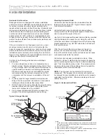
Pre-Installation
Prior to installation, locate and mark all existing underground
utilities, piping, etc. Install loops for new construction before
sidewalks, patios, driveways, and other construction has
begun. During construction, accurately mark all ground loop
piping on the plot plan as an aid in avoiding potential future
damage to the installation.
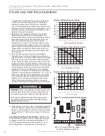
Piping Installation
The typical closed loop ground source system is shown in
Figures 6a and 11a. All earth loop piping materials should be
limited to polyethylene fusion only for in-ground sections of the
loop and it is also recommended for inside piping. Galvanized
or steel
fi
ttings should not be used at any time due to their
tendency to corrode. All plastic to metal threaded
fi
ttings
should be avoided due to their potential to leak in ground
loop applications. Loop temperatures can range between
25 and 110°F [-4 to 43°C]. Flow rates between 2.25 and 3
gpm per ton [2.41 to 3.23 l/m per kW] of cooling capacity is
recommended in these applications.
Test individual horizontal loop circuits before back
fi
lling.
Test vertical U-bends and pond loop assemblies prior to
installation. Pressures of at least 100 psi [689 kPa] should be
used when testing. Do not exceed the pipe pressure rating.
Test entire system when all loops are assembled.
NOTICE!
NOTICE!
If installing MULTIPLE vFlow
™
Internal Variable
Speed Flow Controller units (in parallel) on one loop,
please refer to section ‘Multiple Unit Piping and Flushing’
(later in this document).
Содержание Tranquility 30 TE026
Страница 2: ...This page was intentionally left blank ...


