


16
G e o t h e r m a l H e a t i n g a n d C o o l i n g
Tranquility
®
30 Digital (TE) Series IOM - 60Hz HFC-410A
R e v. : 2 9 M a y, 2 0 1 5 J
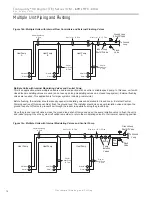
Multiple Unit Piping and Flushing
Often projects require more than one heat pump. Where
possible, it makes sense for multiple units to share a common
ground loop. Common ground loops for multiple units bring
new challenges including the need to avoid backward
fl
ow
through inactive units, increased pumping requirements,
and more complex
fl
ushing needs. Three types of multiple
unit systems are described below along with guidelines for
installation of each type.
vFlow
™
internal variable
fl
ow technology is a great assist
for systems with multiple units. vFlow
™
is available in three
different con
fi
gurations:
1. Internal variable-speed pump for closed loops
2. Internal modulating valve for closed loops
3. Internal modulating valve for open loops
The internal modulating valve for closed loops version is a
low system pressure drop valve that in most cases is not
suitable for open loop systems.
The internal modulating valve for open loops version is a high
system pressure drop valve that in most cases is not suitable
for closed loop systems.
To determine if these valve versions are appropriate for the
available pumping refer to the Tranquility
®
30 Digital (TE)
Series IOM part number 97B0045N04 for performance
characteristics of the valves.
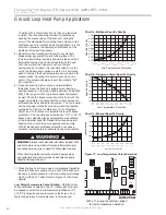
The internal variable speed pump version of vFlow
™
includes
an internal variable speed circulator controlled by the DXM2
microprocessor, internal 3-way
fl
ushing valves, an internal
bladder type expansion tank, and front-mounted pressure
ports that allow access to the pressure drop across the
coaxial heat exchanger only. The pump includes an internal
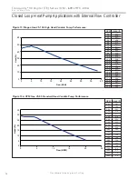
check valve. The pump curves are shown in Figures 13 and
13a. The internal expansion tank will operate as a pressure
battery for the geothermal system. It will absorb
fl
uid from the
loop when loop pressure rises and inject
fl
uid into the loop
when loop pressure falls. In this way the expansion tank will
help to maintain a more constant loop pressure and avoid
fl
at
loops due to seasonal pressure changes in the loop.
When using the internal variable speed pump as the loop
pump in multiple unit installations it is important to ensure
that the variable speed pump can provide adequate
fl
ow
through the heat pump against the loop head when all units
are operating.
Units with UPM Geo pumps should not be combined with
units with Magna Geo pumps on the same loop. UPM Geo
units are best suited for small applications with a single
geothermal heat pump.
It may be possible to
fl
ush a multiple unit system through
the unit’s
fl
ushing valves. Flushing pressure drop of the
valve may be calculated to determine if it is acceptable.
Engineering data for the 3-way
fl
ushing valves can be found
in Table 2.
For example, if a system includes two 2-ton units and four ¾
loop circuits we can calculate the
fl
ushing pressure drop as
follows. From Table 1 we know that it will take 4 gpm to
fl
ush
each ¾” circuit. If there is no provision to isolate the circuits
for
fl
ushing, we will have to
fl
ush with a minimum of 4 circuits
x 4 gpm/circuit = 16 gpm total. A check of other piping sizes
used must be done to ensure that 16 gpm total
fl
ow will
fl
ush
all piping.
Pressure drop through the
fl
ushing valve can be calculated
using the following formula.
Δ
P = (GPM/Cv)
2
where,
Δ
P = pressure drop in psi through the valve while
fl
ushing
GPM =
fl
ushing
fl
ow in gallons per minute
Cv = valve Cv in
fl
ushing mode
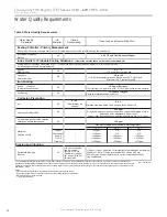
We know from Table 2 that the Cv for the
fl
ushing valve in
a TE026 is 10.3 in the
fl
ushing mode (90°
fl
ow). Therefore,
Δ
P = (GPM/Cv)
2
= (16/10.3)
2
= 2.4 psi per valve (there are
two
fl
ushing valves). So long as the
fl
ushing pump is able to
provide 16 gpm at the
fl
ushing pressure drop of the loop plus
the 2.4 x 2 valves = 4.8 psi of the
fl
ushing valves, the internal
fl
ushing valves may be used. If the
fl
ushing pump is not able
to overcome the pressure drop of the internal
fl
ushing valves,
then larger external
fl
ushing valves must be used.
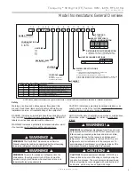
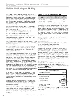
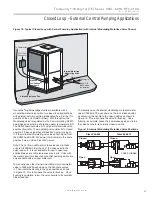
Unit Confi guration
Multiple vFlow
™
units with internal variable-speed
fl
ow
controller and check valve, piped in parallel sharing a
common loop MUST be con
fi
gured for ‘VS PUMP PARALLEL’
in Installer Settings Menu.
Installer Settings
System Con
fi
g
Unit Con
fi
g
Loop Con
fi
g
Table 2: Internal 3-Way Flushing Valve Data
Model
Flushing
Connection
Straight
Flow Cv
90°
Flow Cv
TE026 - 038
3/4" FPT
25
10.3
TE049 - 072
1" FPT
58
14.5
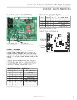
UNIT CONFIGURATION
CURRENT CONFIG TE026
HEAT PUMP FAMILY TE
HEAT PUMP SIZE 026
BLOWER TYPE ECM
LOOP CONFIG VS PUMP
PARALLEL
SELECT OPTION
PREVIOUS SAVE
TE026
TE
Содержание Tranquility 30 TE026
Страница 2: ...This page was intentionally left blank ...


