


3
c l i m a t e m a s t e r. c o m
Tranquility
®
30 Digital (TE) Series IOM - 60Hz HFC-410A
R e v. : 2 9 M a y, 2 0 1 5 J
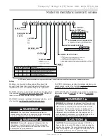
Model Nomenclature: General Overview
WARNING!
WARNING!
CAUTION!
WARNING!
To avoid the release of refrigerant into the
atmosphere, the refrigerant circuit of this unit must be
serviced only by technicians who meet local, state, and
federal pro
fi
ciency requirements.
CAUTION!
To avoid equipment damage, DO NOT use
these units as a source of heating or cooling during the
construction process. The mechanical components and
fi
lters will quickly become clogged with construction dirt
and debris, which may cause system damage.
WARNING!
All refrigerant discharged from this unit must
be recovered WITHOUT EXCEPTION. Technicians must
follow industry accepted guidelines and all local, state,
and federal statutes for the recovery and disposal of
refrigerants. If a compressor is removed from this unit,
refrigerant circuit oil will remain in the compressor. To
avoid leakage of compressor oil, refrigerant lines of the
compressor must be sealed after it is removed.
Safety
Warnings, cautions and notices appear throughout this
manual. Read these items carefully before attempting any
installation, service, or troubleshooting of the equipment.
DANGER: Indicates an immediate hazardous situation, which
if not avoided will result in death or serious injury. DANGER
labels on unit access panels must be observed.
WARNING: Indicates a potentially hazardous situation, which
if not avoided could result in death or serious injury.
CAUTION: Indicates a potentially hazardous situation or an
unsafe practice, which if not avoided could result in minor or
moderate injury or product or property damage.
NOTICE: Noti
fi
cation of installation, operation or maintenance
information, which is important, but which is not hazard-
related.
WARNING!
WARNING!
The EarthPure
®
Application and Service
Manual should be read and understood before attempting
to service refrigerant circuits with HFC-410A.
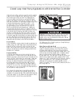
NOTE: Above model nomenclature is a general reference. Consult individual specifi cation sections for detailed information.
1
B = Current Revision
0 2 6
D
G
0
2 C L T
4 5 6
7
8
9
10
11
12
13
14
026
UNIT SIZE
038
RETURN AIR FLOW CONFIGURATION
VOLTAGE
CONTROLS
D = DXM2
B = DXM2 w/Disconnect
4 = DXM2 w/SecureStart
REVISION LEVEL
HEAT EXCHANGER OPTIONS
CABINET
SUPPLY AIR FLOW &
MOTOR CONFIGURATION
TE
1 2
TE = Tranquility
®
30 Digital
SERIES
V
3
V = Vertical Up
CONFIGURATION
No HWG
HWG W/Pump (Standard)
Copper Cupro-Nickel
A
C
J
N
WATER CIRCUIT OPTIONS
S
15
S = Standard
STANDARD
H = Horizontal
049
064
0 = Residential
0 = None
Supply Configuration
T
TEV
B
TEH
S
TEH
Top
Back
Straight
072
1 = Internal Flow Controller Standard Head – Closed Loop
(available for unit sizes 026 and 038 only)
2 = Internal Flow Controller High Head - Closed Loop
5 = Motorized Modulating Valve (Central Pumping Applications) - Closed Loop
6 = Motorized Modulating Valve (Ground Water Applications) - Open Loop
L = Left Return w/ 2” Merv 11 pleated filter and frame
R = Right Return w/ 2” Merv 11 pleated filter and frame
D = Down Flow
A
D
TED
Down
G = 208/230/60/1
In Position 11 and 12, only the following combinations are available:
Without HWG
With HWG
Description
2A
1A
2C
1C
Internal Flow Controller High Head with Copper Water Coil
Internal Flow Controller Standard Head with Copper Water Coil
5A
5C
Motorized Modulating Valve with Copper Water Coil
6J
6N
Motorized Modulating Valve with Cupro-Nickel Water Coil
0A
0C
No vFlow with Copper Water Coil
0J
0N
No vFlow with Cupro-Nickel Water Coil
Содержание Tranquility 30 TE026
Страница 2: ...This page was intentionally left blank ...


