background image

P1788E   06/04

9

140/160PTH.C..

5. What to Do If...

...the torque is too low?
-

Is the throttle exhaust adjusted correctly?

-

Is the flow pressure too low?

-

Is the reverse button not in one of its end positions?

-

Is the inlet screen dirty?

-

Is the muffler dirty?

-

Is sufficient oil in the pulse unit?

6. Repair Instructions

6.1 Motor Disassembly

-

Clamp the tool in a vice with plastic jaws on its pistol grip <1>.

Caution!

Caution!

Do not damage the rubber coating of the grip.

-

Loosen housing <88>/<133> by turning counterclockwise using a
strap wrench.

-

Pull off housing together with pulse unit.

-

Remove countersunk screw <11> and reverse button <10>.

-

Knock pistol grip housing on soft surface and take motor parts out.

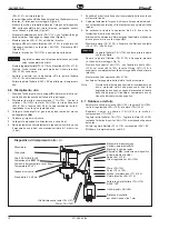
6.2 Trigger Valve Disassembly

-

Lift the plastic trigger button <20> out with 2 screwdrivers

-

Loosen the plug <19> with pin wrench 

<F> 

(pitch 11 mm, diameter

2 mm) counterclockwise.

-

Pull the loosened valve unit vertically down and out

6.3 Motor Assembly

Caution!

Caution!

To avoid damage to the o-rings apply grease (part n°
914392) to them before mounting.


Be sure to assemble the parts in the sequence shown on
the spare parts drawing.

-

Press rotor cover <36> with ball bearing <35> on rotor <41> with
fixture 

<D>

 (8. Assembly Instructions, fig. 8 + 9)

-

Mount air distributor <34>

-

Mount seal ring <29>  in shut-off piston <28>.

-

Slide shut-off ram <32> into rotor (assembly device) and put both
completely into device 

<G>

 (fig. 11)

-

Install actuating bolt <31> and balls <39>

-

Fit compression spring <30> in drilling

-

Fasten pre-assembled shut-off piston <28> to rotor

-

Lift rotor completely (without shut-off ram <32>) from assembly
device. The shut-off piston is interlocked with the rotor

-

Assemble centrifugal force controller <27> - <21> (7. Spare Parts
Exploded View)

-

Put o-ring <33> into pistol grip

-

Insert the pre-assembled parts in the pistol housing. To do so the
slot at the periphery of the air distributor <34> must be adjusted
concentric to the reverse button groove to enable a setting with the
pin

-

Assemble reverse button <10> and countersunk screw <11>.

-

Insert rotor cylinder <38> with shear keys <37> into pistol grip
housing.

-

Insert the blades <40> into the rotor grooves of <41>.

-

Put the ball bearing <43> and the circlip <44> into the rotor cover
<42> and mount all into the pistol grip housing.

Caution!

Caution!

The drill holes in the rotor cover must remain uncovered

-

Assemble sleeve <45>

-

Slide shut-off ram <32> back into the rotor


Do only switch on motor when pulse unit <50>/<95> and
housing <88>/<133> are assembled

Caution!

Caution!

When installing the screen <6>, be sure the circlip <7> is
lying flat on the screen.

6.4 Pulse Unit Disassembly


Allowed only if filling with oil filling unit 

<A>

 can be

guaranteed. The pulse unit must have cooled down to
room temperature.

Caution!

Caution!

Be sure retaining rings are not extended excessively

-

Quick-change model: remove first parts <139> - <135>

-

Remove retaining ring <89>/<134> and pull housing <88>/<133>
off pulse unit.

-

Clamp the hydraulic cylinder  <58>/<103> slightly in a vice with flat
chops (8. Assembly Instructions, fig. 1).


To avoid endangering health or environment, always
comply with the local regulations for security and prevention
of accidents.


Avoid direct skin contact when working with oil to prevent
skin irritations.

-

Remove set bolt <76>/<121>. Remove ball <75>/<120> by turning
the drive shaft <69>/<114>, keeping the opening away from the
body.

-

Loosen the bearing ring <73>/<118> with the device 

<C2>

.

-

Remove the bearing ring above an oil pan and pull the hydraulic
rotor <69>/<114> from the housing.


Hydraulic roller is spring-loaded!

-

By removing the needle roller <84>/<129> all parts built in the
hydraulic rotor can be removed.

-

Clean all parts.

Caution!

Caution!

Always only use original spares from CLECO. Use of
foreign spares entitles the manufacturer of the tool to void
the warranty.

6.5 Assembly of the Pulse Unit

Caution!

Caution!

To avoid damage to the o-rings apply grease (part
n° 914392) to them before mounting.

-

Reassemble by reversing the disassemby process as shown
(7. Spare parts exploded view).

-

Push parts <57> - <52> (   3/4") or <102> to <97> (  7/16" ) onto
the hydraulic cylinder <58>/<103> and secure them with the circlip
<51>/<96>

-

Assemble o-ring <63>/<108>, support ring <62>/<107>, o-ring
<71>/<116> and support ring <72>/<117> on hydraulic rotor <69>/
<114>.

-

Fit O-ring <61>/<106>, needle roll <60>/<105> and sleeve <92>/
<141> in the hydraulic rotor

-

Push fixture 

<E>

 over long side of shaft on hydraulic rotor

(8. Assembly instructions, fig. 2).

-

Insert compression springs and blades over the slots of fixture 

<E>

by pressing them down and turning the hydraulic rotor into the
hydraulic rotor slots (fig. 3).

-

Adjust control blade <68>/<113> (with long shaft end) towards
bore in fixture (fig. 4).

-

Assemble needle roller <59>/<104> into hydraulic cylinder.

Содержание 140PTHC Series

Страница 1: ...se shut off nutsetter Instruction Manual P1788E 2004 06 P T H L C 25 Max capacity Final drive 140 140 Nm 6 Square 3 4 160 160 Nm Q Quick Change 7 16 Design Drehzahl P Pistol grip 25 2500 1 min Torque...

Страница 2: ...ns le pays de l utilisateur doivent tre obligatoirement respect es par toute personne charg e de l installation le fonctionnement et la maintenance de l outil S curit Lire d abord attentivement les co...

Страница 3: ...do y comprendido estas instrucciones y el manual espec fico de este modelo S mbolos Atenci n Este s mbolo indica un situaci n potencial de peligro Pueden producirse lesiones f sicas a las personas si...

Страница 4: ...s a h f u a l r e e L d e e p s e e r f e d i v n o i t a t o r o t o u v a t i c o l e v o c a v n e d a d i c o l e v n e s l u P e s l u p r e s l u p i s l u p m i o s l u p x a m n i m x a m n i...

Страница 5: ...n Richtung verdrehen Drehzahl wird reduziert Drehzahl 1800 min nicht unterschreiten da sonst eine unruhige Leerlaufdrehzahl entstehen kann 4 Inspektion und Wartung Eine regelm ige Inspektion ist unerl...

Страница 6: ...eh use montieren Achtung Achtung Rotordeckelbohrungen m en offen bleiben H lse 45 montieren Abschaltst ssel 32 wieder in Rotor einschieben Motorbaustein darf nur mit aufgesteckter Impulseinheit 50 95...

Страница 7: ...wiederholen bis Blasenbildung gegen Null l uft Impuls Einheit abkuppeln Adapter herausdrehen und ein paar Tropfen l mit Injektionsspritze B nachf llen Kugel 75 120 montieren und Gewindestift 76 121 fe...

Страница 8: ...ecome unsteady 4 Inspection and Maintenance Regular inspection is essential in order to prevent breakdowns high repair costs and long downtimes associated with the pulse nutsetter Always follow and us...

Страница 9: ...ip housing Caution Caution The drill holes in the rotor cover must remain uncovered Assemble sleeve 45 Slide shut off ram 32 back into the rotor Do only switch on motor when pulse unit 50 95 and housi...

Страница 10: ...bubbles is negligible Disconnect the pulse unit remove the adapter and add a few drops of oil with syringe B Install the ball 75 120 and tighten the set bolt 76 121 2 9 0 3 Nm Caution Caution The bea...

Страница 11: ...e Un contr le r gulier est indispensable pour viter des pannes asso ci es des co ts de r paration lev s et des temps d immobilisation prolong s de la visseuse impulsions Lors des op rations de contr l...

Страница 12: ...is t te conique 11 Introduire la culasse de rotor 38 avec le ressort d ajustage 37 dans le bo tier pistolet Fixer les palettes 40 dans les fentes du rotor 41 Ins rer le roulement bille 43 et circlip 4...

Страница 13: ...6 8 jusqu ce que presque toutes les bulles d air soient expuls es si besoin D coupler l unit d impulsion d visser l adaptateur et remplir quelques gouttes d huile avec l injecteur B Monter la bille 7...

Страница 14: ...i sotto 1800 1 min in quanto altrimenti si provoca un funzionamento a vuoto irregolare 4 Controllo e manutenzione Un controllo regolare indispensabile per evitare anomalie di funzionamento elevati cos...

Страница 15: ...vite a testa piatta 11 Infilare il cilindro rotore 38 con la chiavetta 37 nel corpo pistola Infilare le lamelle 40 negli intagli del rotore 41 Collocare il cuscinetto 43 con seeger 44 nel coperchio ro...

Страница 16: ...ressione relativa l olio mancante viene spinto nell unit impulsi 9 Se necessario ripetere le operazioni da 6 a 8 fino a che la formazione di bolle sia quasi nulla Disinserire l unit impulsi sfilare ru...

Страница 17: ...1800 min ya que de esta manera se puede producir un n mero de revoluciones intranquilo en la marcha en vac o 4 Inspecci n y mantenimiento Es indispensable una inspecci n regular para evitar eventuales...

Страница 18: ...en la hendidura del rotor 41 Montar cojinete 43 y anillo de seguridad 44 en el carter del motor 42 entrarlo completamente en la carcasa Losagujerosenlatapadelrotortienenquequedarabierto Montar mangui...

Страница 19: ...n la unidad de impulso 9 Si es necesario volver a repetir los pasos 6 hasta 8 hasta que la formaci n de burbujas se reduzca a cero Desacople la unidad de impulso saque el adaptador e introduzca alguna...

Страница 20: ...ncluded in motor service kit 542719 Comprise dans le motor service kit 542719 Contenuto nel motor service kit 542719 Viene con la motor service kit 542719 siehe 10 Hinweise see 10 Notes voir 10 Remarq...

Страница 21: ...p s e t s u j a e d o l l i n a 5 0 X 6 1 X 0 1 3 2 7 8 7 4 1 9 1 g n i R O g n i r o e u q i r o t t n i o j O d a o l l e n a a c i r t a t n u j 5 1 X 0 1 4 2 7 4 4 2 3 9 1 r e t l a h l e g u K t...

Страница 22: ...0 enthalten 89 comes with 50 89 comprise dans 50 89 contenuto nel 50 89 viene con 50 Teil des Hydraulik Service Kits 542720 Included in hydraulic service kit 542720 Comprise dans le hydraulique servic...

Страница 23: ...e t S m s a e d a l b l o r t n o c l p c e l r t n o c e m a l l p c o l l o r t n o c i d a t t e l a p l p c l o r t n o c e d a t e l a p 8 6 9 0 3 2 3 9 1 l p k e l l e m a l r e u e t S m s a e...

Страница 24: ...o Cambio R pido 134 in 95 enthalten 134 comes with 95 134 comprise dans 95 134 contenuto nel 95 134 viene con 95 Teil des Hydraulik Service Kits 542720 Included in hydraulic service kit 542720 Compris...

Страница 25: ...e h c s r e u e t S c s i d l o r t n o c e l r t n o c e l l e d n o r o d n a m o c i d o c s i d a r b o i n a m e d o c s i d 6 1 1 2 1 7 4 2 9 1 g n i R O g n i r o e u q i r o t t n i o j O d a...

Страница 26: ...rage de la bague du palier 73 118 Svitare la ghiera filettata 73 118 Aflojar el anillo 73 118 Impuls Einheit Pulse unit Unit d impulsion Unit ad impulsi Unidad de impulso C 58 103 Montage der Impuls E...

Страница 27: ...palier 73 118 Montaggio della ghiera filettata 73 118 Apriete del anillo 73 118 4 6 68 113 67 112 58 103 E 59 104 7 Impuls Einheit Pulse unit Unit d impulsion Unit ad impulsi Unidad de impulso C 73 11...

Страница 28: ...see dimension X Enfoncer le palier voir X Piantare i cucinetti vede X Empujar el rodamiento ver X 8 X 0 02 0 06 mm 0 0008 0 0024 in X 41 35 36 D1 D2 D3 3 Rotor auspressen Rotor disassembly D monter le...

Страница 29: ...3 9 l e i p s l a i x A g n u t h c i r r o V l a i x a r o f e r u t x i f t n e m e v o m u e j r u o p f i t i s o p s i d l a i x a o c o i g r e p o v i t i s o p s i d e l a i s s a l a i x a o...

Страница 30: ...ferencia Fett Best Nr Grease Order no Graisse R f rence 914392 Grasso Codice Grasa N referencia x e d n I t n e m o m s g u z n A e u q r o t g n i n e t h g i t e g a r r e s e d e l p u o c a r u s...

Страница 31: ......

Страница 32: ...2 802 1718 Fax 425 497 0496 Fax 717 757 5063 Tel 905 501 4785 Fax 905 501 4786 Germany England France China Cooper Power Tools Cooper Power Tools Cooper Power Tools SAS Cooper China Co Ltd GmbH Co OHG...

Отзывы: