750-204
Profire D/LND
2-9
2.12 — Gas Piping
blow out the pipe line, removing all dirt, pipe scale, and sediment. This type of valve is actuated by the system
pressure which enters the body beneath the main valve. Valve loading is provided by a spring that can be
adjusted to the desired set pressure.
To adjust the set pressure, remove the top cap, loosen the brass locknut and adjust the pressure with the steel
setscrew. By increasing the compression on the spring, screwing down the screw, you increase the set pressure
within the limits of the spring range. Reversing the setscrew lowers the set pressure.
Adjust to 10-15 PSI for No. 2 oil systems and 15-20 PSI for heavy oils. When the desired pressure is reached,
tighten the locknut and replace the to cap and gasket.
2.12 — Gas Piping
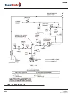
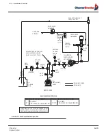
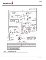
Refer to Figures 2-16 to 2-19 for typical gas piping schematics.
Gas service and house piping must supply the quantity of gas demanded by the unit at the pressure required at
the burner gas train inlet. All piping must be in strict accordance with applicable codes, ordinances, and regula-
tions of the supplying utility. In the absence of other codes, piping should be in accordance with the following
prevailing standards:
•
National Fuel Gas Code NFPA No. 54
•
ANSI No. Z 223.1
For Canada:
•
Canadian Gas Association (CGA) B149
•
Canadian Standards Association (CSA) B140
Gas train components upstream of the butterfly valve are shipped loose. These components should be mounted
by the installer as close to the butterfly valve as practical. Normally, the control train is ordered to suit a particu-
lar code or insurance regulation, such as Underwriters Laboratories, Inc., CGA, Factory Mutual, or Industrial Risk
Insurance.
Arrange gas piping at the burner so that the burner is accessible for servicing without disassembly.
The gas pilot supply line must be connected upstream of the main gas regulator. If a reducing bushing is required
between the house piping and the burner piping, it should be close to the burner shutoff valve.
The gas piping must be internally clean and free of foreign material. Before using in service, a leak test must be
performed.
2.13 — Installation Checklist
All burners are carefully assembled and tested at the factory, but before being placed in service, all connectors
should again be checked for looseness caused during shipment.
Содержание ProFire D Series
Страница 2: ......
Страница 3: ...PROFIRE D LND Installation Operation and Service Manual Manual Number 750 204 Release Date July 2019...
Страница 8: ......
Страница 16: ...viii 750 204 Profire D LND...
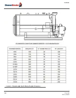
Страница 30: ...Installation 2 2 750 204 Profire D LND FIGURE 2 1 Recommended Scotch Marine Chamber Dimensions...
Страница 39: ...750 204 Profire D LND 2 11 2 13 Installation Checklist FIGURE 2 7 Recommended Pipe Size...
Страница 40: ...Installation 2 12 750 204 Profire D LND FIGURE 2 8 Recommended Pipe Size...
Страница 42: ...Installation 2 14 750 204 Profire D LND FIGURE 2 10 Recommended Pipe Size...
Страница 43: ...750 204 Profire D LND 2 15 2 13 Installation Checklist FIGURE 2 11 Recommended Pipe Size...
Страница 44: ...Installation 2 16 750 204 Profire D LND FIGURE 2 12 Recommended Pipe Size...
Страница 45: ...750 204 Profire D LND 2 17 2 13 Installation Checklist FIGURE 2 13 Recommended Pipe Size...
Страница 46: ...Installation 2 18 750 204 Profire D LND FIGURE 2 14 Recommended Pipe Size...
Страница 47: ...750 204 Profire D LND 2 19 2 13 Installation Checklist FIGURE 2 15 Multiple Boilers Installation Heavy Oil...
Страница 48: ...Installation 2 20 750 204 Profire D LND FIGURE 2 16 Typical UL Gas Piping FIGURE 2 17 Typical UL Gas Piping...
Страница 50: ...Installation 2 22 750 204 Profire D LND...
Страница 69: ...750 204 Profire D LND 4 11 4 8 Firing Rate Controls FIGURE 4 7 Motor Rotations...
Страница 70: ...Adjustments 4 12 750 204 Profire D LND...
Страница 82: ...Maintenance 5 12 750 204 Profire D LND...
Страница 88: ...Troubleshooting 6 6 750 204 Profire D LND...
Страница 98: ...Flue Gas Recirculation 8 6 750 204 Profire D LND FIGURE 8 4 FGR Piping and Valve Sizes...
Страница 100: ...Flue Gas Recirculation 8 8 750 204 Profire D LND FIGURE 8 6 20 PPM Head Assembly...
Страница 104: ...Parts Lists and Drawings 9 4 750 204 Profire D LND 9 4 Parts Lists and Drawings 9 4 2 Blast Tube Assembly D42 336...
Страница 106: ...Parts Lists and Drawings 9 6 750 204 Profire D LND 9 4 2 Blast Tube Assembly D378 420...
Страница 108: ...Parts Lists and Drawings 9 8 750 204 Profire D LND 9 4 3 Blower Housing Assembly D42 175...
Страница 110: ...Parts Lists and Drawings 9 10 750 204 Profire D LND 9 4 4 Blower Housing Assembly D210 336...
Страница 112: ...Parts Lists and Drawings 9 12 750 204 Profire D LND 9 4 5 Blower Housing Assembly D378 420...
Страница 114: ...Parts Lists and Drawings 9 14 750 204 Profire D LND 9 4 6 Compressor Set D42 145...
Страница 116: ...Parts Lists and Drawings 9 16 750 204 Profire D LND 9 4 7 Compressor Set D175 336...
Страница 118: ...Parts Lists and Drawings 9 18 750 204 Profire D LND 9 4 8 Compressor Set D378 420...
Страница 120: ...Parts Lists and Drawings 9 20 750 204 Profire D LND 9 4 9 Control Package Fireye...
Страница 122: ...Parts Lists and Drawings 9 22 750 204 Profire D LND 9 4 10 Control Package Honeywell...
Страница 124: ...Parts Lists and Drawings 9 24 750 204 Profire D LND 9 4 11 Damper Assembly D42 420...
Страница 126: ...Parts Lists and Drawings 9 26 750 204 Profire D LND 9 4 12 Damper Assembly LND42 420...
Страница 128: ...Parts Lists and Drawings 9 28 750 204 Profire D LND 9 4 13 Drawer Assembly D42 63...
Страница 130: ...Parts Lists and Drawings 9 30 750 204 Profire D LND 9 4 14 Drawer Assembly D84 145...
Страница 132: ...Parts Lists and Drawings 9 32 750 204 Profire D LND 9 4 15 Drawer Assembly D175 336...
Страница 134: ...Parts Lists and Drawings 9 34 750 204 Profire D LND 9 4 16 Drawer Assembly D378 420...
Страница 136: ...Parts Lists and Drawings 9 36 750 204 Profire D LND 9 4 17 Firing Head Assembly D42 420...
Страница 139: ...750 204 Profire D LND 9 39 9 4 Parts Lists and Drawings 9 4 19 Oil Heater D42 420...
Страница 141: ...750 204 Profire D LND 9 41 9 4 Parts Lists and Drawings 9 4 20 Oil Metering Assembly DL DLG DM DMG42 145...
Страница 143: ...750 204 Profire D LND 9 43 9 4 Parts Lists and Drawings 9 4 21 Oil Metering Assembly DL DLG DM DMG175 420 DE DEG42 420...
Страница 146: ...Parts Lists and Drawings 9 46 750 204 Profire D LND 9 4 22 Oil Metering Assembly D378 420...
Страница 152: ...Parts Lists and Drawings 9 52 750 204 Profire D LND 9 4 26 Modulation Cam Trim Low NOx or Left Hand Gas...
Страница 156: ...750 204 Profire D LND...
Страница 159: ......
Страница 160: ......


