


Introduction
1-8
750-204
Profire D/LND
1.
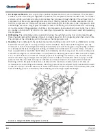
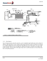
Air Compressor Module.
Air is supplied by a positive displacement rotary vane compressor. This provides a
constant volume of atomizing air regardless of pressure. The compressor module includes motor, air-oil reser-
voir tank, air filter, and lube oil cooling coil. Air enters the compressor through the filter. The air flows from the
compressor into the air-oil separating and reservoir tank. Filtering material and baffles separate the lube oil
from the compressed air. The tank air pressure forces lubricating oil from the tank to the compressor to lubri-
cate bearings and vanes. A sight glass indicates the level of lubricating oil in the air/oil reservoir. Lubricating
oil must be visible in the gauge glass at all times. Air compression heat is absorbed in part by the flow of lube
oil, creating a hot oil mist. The air/oil mist is cooled by a coil assembly. Lube oil is also cooled before entering
the compressor.
2.
Oil Metering.
The oil metering unit is cored with channels through the housing. Fuel oil circulates through
these channels keeping the metering unit warm to prevent heavy oils from congealing when the burner is idle.
The operation of the oil metering unit is the same as the integral air/oil unit.
3.
Operation.
Fuel is delivered to the positive displacement metering pump at 10 to 15 psi. Metered oil is deliv-
ered to the common port of a 3-way solenoid valve for transfer to the burner nozzle through the normally
closed port or back to the storage tank through the normally open port. During pre- and post-purge, metered
oil is returned to the tank. During normal firing, all metered oil is delivered to the nozzle. Heavy oil burners
have a supplementary nozzle line heater between the metering and the 3-way valve. Air enters a rotary vane
compressor through an air cleaner where it is compressed to atomizing pressure. Air flows from the compres-
sor to an air/oil tank which serves the multiple purpose of dampening air pulsation, lube oil mist recovery,
lube oil and atomizing air storage. The compressor rotor is cooled and lubricated continuously by oil under
pressure from the air/oil tank. Oil vapor is extracted by a mist eliminator in the upper section of the tank.
Atomizing air from the upper tank section is delivered to the nozzle at a constant volume. Air pressure
increases as the burner firing rate increases. Atomizing pressure may be adjusted by the needle valve located
on the air-oil pump. The valve allows air to be bled from the tank to the compressor inlet. Delivery rate of the
fuel oil metering pump is controlled by the modulating motor through adjustable linkage.
FIGURE 1-6.
Integral Oil-Air Metering System and Tank
Содержание ProFire D Series
Страница 2: ......
Страница 3: ...PROFIRE D LND Installation Operation and Service Manual Manual Number 750 204 Release Date July 2019...
Страница 8: ......
Страница 16: ...viii 750 204 Profire D LND...
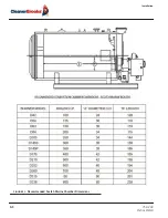
Страница 30: ...Installation 2 2 750 204 Profire D LND FIGURE 2 1 Recommended Scotch Marine Chamber Dimensions...
Страница 39: ...750 204 Profire D LND 2 11 2 13 Installation Checklist FIGURE 2 7 Recommended Pipe Size...
Страница 40: ...Installation 2 12 750 204 Profire D LND FIGURE 2 8 Recommended Pipe Size...
Страница 42: ...Installation 2 14 750 204 Profire D LND FIGURE 2 10 Recommended Pipe Size...
Страница 43: ...750 204 Profire D LND 2 15 2 13 Installation Checklist FIGURE 2 11 Recommended Pipe Size...
Страница 44: ...Installation 2 16 750 204 Profire D LND FIGURE 2 12 Recommended Pipe Size...
Страница 45: ...750 204 Profire D LND 2 17 2 13 Installation Checklist FIGURE 2 13 Recommended Pipe Size...
Страница 46: ...Installation 2 18 750 204 Profire D LND FIGURE 2 14 Recommended Pipe Size...
Страница 47: ...750 204 Profire D LND 2 19 2 13 Installation Checklist FIGURE 2 15 Multiple Boilers Installation Heavy Oil...
Страница 48: ...Installation 2 20 750 204 Profire D LND FIGURE 2 16 Typical UL Gas Piping FIGURE 2 17 Typical UL Gas Piping...
Страница 50: ...Installation 2 22 750 204 Profire D LND...
Страница 69: ...750 204 Profire D LND 4 11 4 8 Firing Rate Controls FIGURE 4 7 Motor Rotations...
Страница 70: ...Adjustments 4 12 750 204 Profire D LND...
Страница 82: ...Maintenance 5 12 750 204 Profire D LND...
Страница 88: ...Troubleshooting 6 6 750 204 Profire D LND...
Страница 98: ...Flue Gas Recirculation 8 6 750 204 Profire D LND FIGURE 8 4 FGR Piping and Valve Sizes...
Страница 100: ...Flue Gas Recirculation 8 8 750 204 Profire D LND FIGURE 8 6 20 PPM Head Assembly...
Страница 104: ...Parts Lists and Drawings 9 4 750 204 Profire D LND 9 4 Parts Lists and Drawings 9 4 2 Blast Tube Assembly D42 336...
Страница 106: ...Parts Lists and Drawings 9 6 750 204 Profire D LND 9 4 2 Blast Tube Assembly D378 420...
Страница 108: ...Parts Lists and Drawings 9 8 750 204 Profire D LND 9 4 3 Blower Housing Assembly D42 175...
Страница 110: ...Parts Lists and Drawings 9 10 750 204 Profire D LND 9 4 4 Blower Housing Assembly D210 336...
Страница 112: ...Parts Lists and Drawings 9 12 750 204 Profire D LND 9 4 5 Blower Housing Assembly D378 420...
Страница 114: ...Parts Lists and Drawings 9 14 750 204 Profire D LND 9 4 6 Compressor Set D42 145...
Страница 116: ...Parts Lists and Drawings 9 16 750 204 Profire D LND 9 4 7 Compressor Set D175 336...
Страница 118: ...Parts Lists and Drawings 9 18 750 204 Profire D LND 9 4 8 Compressor Set D378 420...
Страница 120: ...Parts Lists and Drawings 9 20 750 204 Profire D LND 9 4 9 Control Package Fireye...
Страница 122: ...Parts Lists and Drawings 9 22 750 204 Profire D LND 9 4 10 Control Package Honeywell...
Страница 124: ...Parts Lists and Drawings 9 24 750 204 Profire D LND 9 4 11 Damper Assembly D42 420...
Страница 126: ...Parts Lists and Drawings 9 26 750 204 Profire D LND 9 4 12 Damper Assembly LND42 420...
Страница 128: ...Parts Lists and Drawings 9 28 750 204 Profire D LND 9 4 13 Drawer Assembly D42 63...
Страница 130: ...Parts Lists and Drawings 9 30 750 204 Profire D LND 9 4 14 Drawer Assembly D84 145...
Страница 132: ...Parts Lists and Drawings 9 32 750 204 Profire D LND 9 4 15 Drawer Assembly D175 336...
Страница 134: ...Parts Lists and Drawings 9 34 750 204 Profire D LND 9 4 16 Drawer Assembly D378 420...
Страница 136: ...Parts Lists and Drawings 9 36 750 204 Profire D LND 9 4 17 Firing Head Assembly D42 420...
Страница 139: ...750 204 Profire D LND 9 39 9 4 Parts Lists and Drawings 9 4 19 Oil Heater D42 420...
Страница 141: ...750 204 Profire D LND 9 41 9 4 Parts Lists and Drawings 9 4 20 Oil Metering Assembly DL DLG DM DMG42 145...
Страница 143: ...750 204 Profire D LND 9 43 9 4 Parts Lists and Drawings 9 4 21 Oil Metering Assembly DL DLG DM DMG175 420 DE DEG42 420...
Страница 146: ...Parts Lists and Drawings 9 46 750 204 Profire D LND 9 4 22 Oil Metering Assembly D378 420...
Страница 152: ...Parts Lists and Drawings 9 52 750 204 Profire D LND 9 4 26 Modulation Cam Trim Low NOx or Left Hand Gas...
Страница 156: ...750 204 Profire D LND...
Страница 159: ......
Страница 160: ......


