Maintenance
5-6
750-204
Profire D/LND
5.8 — Diffuser
The diffuser is factory set and does not require attention under normal operating conditions. If fouled with car-
bon, the diffuser should be removed for cleaning.
1.
First remove the electrode and scanner leads, the gas pilot assembly, air and oil tubes, and the nozzle support
assembly before attempting to remove the diffuser.
2.
Mark the diffuser’s relative position to the blast tube with a scribed or pencil line where the three mounting
screws are located, to insure that the diffuser is placed back in the same position.
3.
Remove the three screws holding the diffuser to the blast tube and slowly pull the diffuser along the blast tube
towards the firing head. Keep the diffuser as parallel as possible. If it should become stuck or tight, do not
apply any tool which would distort the shape or blade configuration. A small wooden block tapped gently
against the diffuser’s outer edge will help expedite its removal.
4.
Clean all carbon from the diffuser vanes and reinstall in reverse order of disassembly, aligning the diffuser with
the scribed marks. Do not attempt to drive the diffuser back along the blast tube with anything other than a
small block of wood tapped against the diffuser’s outer edge.
5.
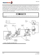
When reinstalling, be sure the diffuser is centered with the proper distance as shown in Figures 5-2 and 5-3.
5.9 — Firing Rate Controls
Check all rods and linkages. Make sure all connections are tight. Adjust if necessary. Perform a combustion test
as explained in Chapter 4, and readjust the burner if necessary.
5.10 — Burner Mounting Inspection
The seal between the burner flange and furnace front plate must not permit combustion gases to escape. Peri-
odic inspection is important. Replace the gasket if necessary. Inspect the burner head for signs of discoloration.
A change in the head color paint might indicate gas leakage between the dry oven and the boiler refractory. If
leakage occurs, refer to Chapter 2, Section 2.4 for proper sealing procedure.
Do not attempt to use a wire or a sharp metal tool to clean the nozzle orifice as this will distort the fine orifice and
ruin the nozzle. Use a sharp pointed piece of soft wood.
NOTE:
It is essential that the cam spring, cam follower bearing wheel, and cam follower arm at the pivot point be
greased sparingly every month to ensure smooth operation of the cam assembly. Regular automotive bearing grease
should be used.
!
Caution
Содержание ProFire D Series
Страница 2: ......
Страница 3: ...PROFIRE D LND Installation Operation and Service Manual Manual Number 750 204 Release Date July 2019...
Страница 8: ......
Страница 16: ...viii 750 204 Profire D LND...
Страница 30: ...Installation 2 2 750 204 Profire D LND FIGURE 2 1 Recommended Scotch Marine Chamber Dimensions...
Страница 39: ...750 204 Profire D LND 2 11 2 13 Installation Checklist FIGURE 2 7 Recommended Pipe Size...
Страница 40: ...Installation 2 12 750 204 Profire D LND FIGURE 2 8 Recommended Pipe Size...
Страница 42: ...Installation 2 14 750 204 Profire D LND FIGURE 2 10 Recommended Pipe Size...
Страница 43: ...750 204 Profire D LND 2 15 2 13 Installation Checklist FIGURE 2 11 Recommended Pipe Size...
Страница 44: ...Installation 2 16 750 204 Profire D LND FIGURE 2 12 Recommended Pipe Size...
Страница 45: ...750 204 Profire D LND 2 17 2 13 Installation Checklist FIGURE 2 13 Recommended Pipe Size...
Страница 46: ...Installation 2 18 750 204 Profire D LND FIGURE 2 14 Recommended Pipe Size...
Страница 47: ...750 204 Profire D LND 2 19 2 13 Installation Checklist FIGURE 2 15 Multiple Boilers Installation Heavy Oil...
Страница 48: ...Installation 2 20 750 204 Profire D LND FIGURE 2 16 Typical UL Gas Piping FIGURE 2 17 Typical UL Gas Piping...
Страница 50: ...Installation 2 22 750 204 Profire D LND...
Страница 69: ...750 204 Profire D LND 4 11 4 8 Firing Rate Controls FIGURE 4 7 Motor Rotations...
Страница 70: ...Adjustments 4 12 750 204 Profire D LND...
Страница 82: ...Maintenance 5 12 750 204 Profire D LND...
Страница 88: ...Troubleshooting 6 6 750 204 Profire D LND...
Страница 98: ...Flue Gas Recirculation 8 6 750 204 Profire D LND FIGURE 8 4 FGR Piping and Valve Sizes...
Страница 100: ...Flue Gas Recirculation 8 8 750 204 Profire D LND FIGURE 8 6 20 PPM Head Assembly...
Страница 104: ...Parts Lists and Drawings 9 4 750 204 Profire D LND 9 4 Parts Lists and Drawings 9 4 2 Blast Tube Assembly D42 336...
Страница 106: ...Parts Lists and Drawings 9 6 750 204 Profire D LND 9 4 2 Blast Tube Assembly D378 420...
Страница 108: ...Parts Lists and Drawings 9 8 750 204 Profire D LND 9 4 3 Blower Housing Assembly D42 175...
Страница 110: ...Parts Lists and Drawings 9 10 750 204 Profire D LND 9 4 4 Blower Housing Assembly D210 336...
Страница 112: ...Parts Lists and Drawings 9 12 750 204 Profire D LND 9 4 5 Blower Housing Assembly D378 420...
Страница 114: ...Parts Lists and Drawings 9 14 750 204 Profire D LND 9 4 6 Compressor Set D42 145...
Страница 116: ...Parts Lists and Drawings 9 16 750 204 Profire D LND 9 4 7 Compressor Set D175 336...
Страница 118: ...Parts Lists and Drawings 9 18 750 204 Profire D LND 9 4 8 Compressor Set D378 420...
Страница 120: ...Parts Lists and Drawings 9 20 750 204 Profire D LND 9 4 9 Control Package Fireye...
Страница 122: ...Parts Lists and Drawings 9 22 750 204 Profire D LND 9 4 10 Control Package Honeywell...
Страница 124: ...Parts Lists and Drawings 9 24 750 204 Profire D LND 9 4 11 Damper Assembly D42 420...
Страница 126: ...Parts Lists and Drawings 9 26 750 204 Profire D LND 9 4 12 Damper Assembly LND42 420...
Страница 128: ...Parts Lists and Drawings 9 28 750 204 Profire D LND 9 4 13 Drawer Assembly D42 63...
Страница 130: ...Parts Lists and Drawings 9 30 750 204 Profire D LND 9 4 14 Drawer Assembly D84 145...
Страница 132: ...Parts Lists and Drawings 9 32 750 204 Profire D LND 9 4 15 Drawer Assembly D175 336...
Страница 134: ...Parts Lists and Drawings 9 34 750 204 Profire D LND 9 4 16 Drawer Assembly D378 420...
Страница 136: ...Parts Lists and Drawings 9 36 750 204 Profire D LND 9 4 17 Firing Head Assembly D42 420...
Страница 139: ...750 204 Profire D LND 9 39 9 4 Parts Lists and Drawings 9 4 19 Oil Heater D42 420...
Страница 141: ...750 204 Profire D LND 9 41 9 4 Parts Lists and Drawings 9 4 20 Oil Metering Assembly DL DLG DM DMG42 145...
Страница 143: ...750 204 Profire D LND 9 43 9 4 Parts Lists and Drawings 9 4 21 Oil Metering Assembly DL DLG DM DMG175 420 DE DEG42 420...
Страница 146: ...Parts Lists and Drawings 9 46 750 204 Profire D LND 9 4 22 Oil Metering Assembly D378 420...
Страница 152: ...Parts Lists and Drawings 9 52 750 204 Profire D LND 9 4 26 Modulation Cam Trim Low NOx or Left Hand Gas...
Страница 156: ...750 204 Profire D LND...
Страница 159: ......
Страница 160: ......

