Chapter 2: Ceiling Mount Installation
9
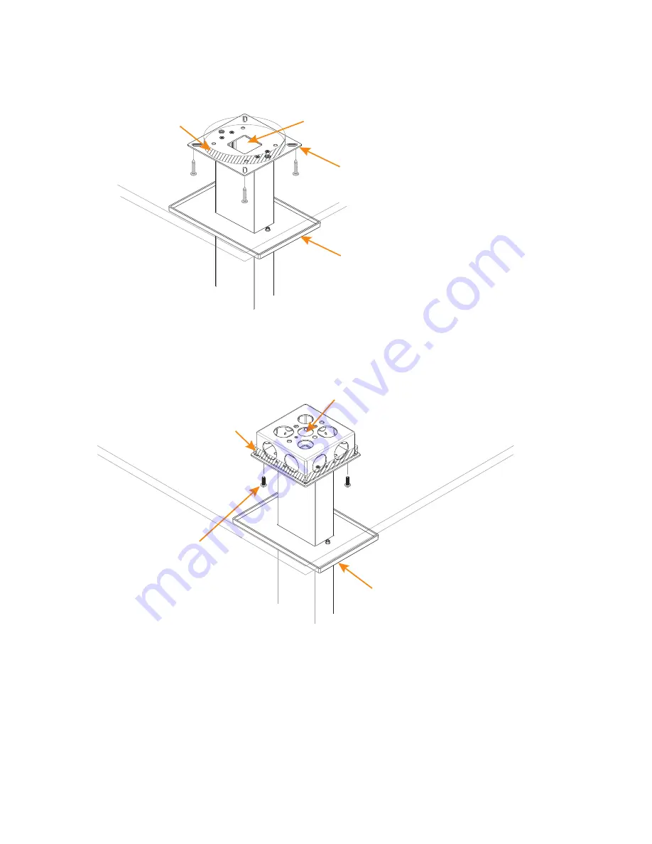
Attach the Ceiling/Wall
Mounting Plate to the ceiling
NOTE: Screws not included. Installer
responsible to obtain appropriate
hardware.
Trim Plate on
Suspension Column
Cutout through
Soilid Ceiling
Feed the LINK IN, LINK OUT and PoE cables
down through the Suspension Column
Cutout through
Soilid Ceiling
or Suspended
Ceiling
Attach the Ceiling/Wall
Mounting Plate to a
secure junction box
NOTE: Junction box and
junction box screws
not included.
Trim Plate on
Suspension Column
Feed LINK IN, LINK OUT and PoE cables
down through the junction box and
Suspension Column
»
IMPORTANT: The installer is responsible to be sure the Beamforming Microphone
Array is firmly attached to sturdy support (studs, a junction box attached to the
structure, or other mounting hardware) to hold the weight of the Beamforming
Microphone Array and its mounting hardware.
Feed the LINK IN, LINK OUT and PoE cables (not shown) down through the assembly, then attach
the assembly to the solid ceiling or junction box as shown in the following diagrams.
»
IMPORTANT: The standard junction box used is 4” square (101.6mm) with the screw
holes in the corners spaced 4.77” (.121.2mm) diagonally corner-to-corner.
Содержание Beamforming Microphone Array
Страница 1: ...Beamforming Microphone Array Group Microphone for Professional Conferencing Installation Guide...
Страница 4: ......
Страница 8: ...4 Beamforming Microphone Array...


