background image

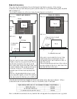
Material Clearances 

Your stove must be installed on a floor with adequate load-bearing capacity.  If the existing 
construction does not meet this pre-requisite, suitable measures (e.g. load distributing plate) should be 
taken to achieve it.   
Care should be taken to level the stove using the adjusting screws in the feet. 


All walls shown in the above diagrams are non-combustible unless otherwise indicated.  All non-
combustible walls closer than 300mm to the stove should be at least 75mm thick. 
 

MINIMUM DISTANCE TO COMBUSTIBLE MATERIAL 

Behind the stove 

450mm 

At the side of the stove 

400mm 

To furniture (in front of the stove) 

700mm 

 
Note: combustible material refers to any material that will degrade when subjected to heat e.g. plaster. 
 

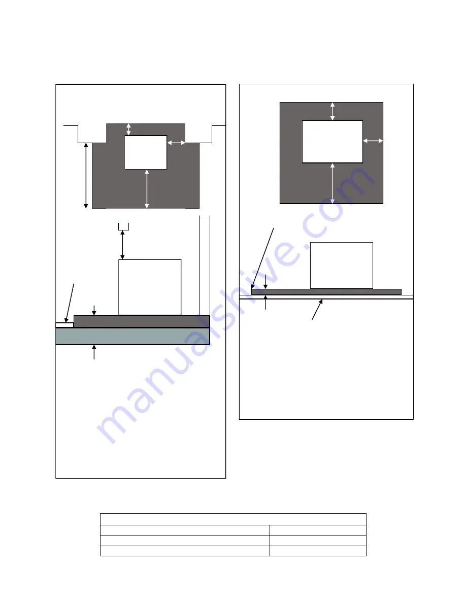
FIREPLACE RECESS 

Plan view: 


Side view: 


The stove can be recessed into a suitably sized 
fireplace, but a free air gap of at least 150 mm 
must be left around the sides and top of the 
stove and at least 50mm at the back of the stove 
to obtain maximum heat output and for access 
to the rear of the stove.  The hearth should 
extend at least 300 mm from the front of the 
stove. 
The stove should stand wholly above a solid, 
non-combustible hearth, at least 125 mm thick 
(this may include the thickness of a solid floor). 

Change in level to mark 
safe perimeter 

FREE-STANDING 

Plan view: 


Side view: 


If the stove is not to stand in a recess, it may 
stand wholly above a hearth made of non-
combustible board / sheet  material or tiles, at 
least 12mm thick. 
The hearth should extend at least 150 mm from 
the sides and rear of the stove, and at least 300 
mm from the front of the stove. 

At least 
12mm 

Stove 

Combustible material 

50 mm 

500 mm 
from 
jamb 

Stove 

125 mm 

150 mm 

Combustible 
material 

Stove 

150 mm 

300 mm 

150 mm 

Stove 

300 mm 

150


mm


Содержание Norreskoven

Страница 1: ...ilding Control Officer can approve the completed installation should a non accredited engineer undertake the installation It is an offence under UK law not to comply with this advice Please hand these instructions to the stove user when the installation is complete Leave the system ready for operation and instruct the user in the correct use of the appliance and operation of controls v01 11b ...

Страница 2: ...S EN 13240 Total Efficiency 73 5 Nominal Heat Output 4 4 kW Mean CO Emission at 13 O2 0 17 Mean Flue Gas Temperature 311 C Flue Gas Mass Flow 4 6 g s This appliance is not suitable for use in a shared flue This appliance is suitable for intermittent burning ...

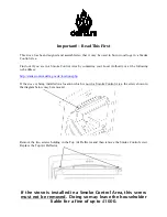
Страница 3: ...p smokecontrol defra gov uk locations php If the stove is being installed in a location which is not in a Smoke Control Area the screw shown in the diagram below may be removed Remove the two screws holding in the Top Air Deflector and then remove the Smoke Control screw Replace the Top Air Deflector If the stove is installed in a Smoke Control Area this screw must not be removed Doing so may leav...

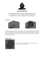
Страница 4: ...he flue collar and blanking plate until finger tight Place the gasket in position on the top plate of the stove and lower the flue collar or blanking plate as required on to the stove top taking care to line up the studs with the fixing holes Secure in place using the M6 nuts and washers Fit the two M8 coach bolts in the flue collar to blank off the optional damper handle holes Blanking Plate Fit ...

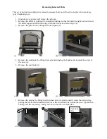
Страница 5: ...wering it into the firebox and removing it a 3 Remove the grate bars by lifting them out in pairs b a b 4 Remove the side bricks by lifting them up and swinging the bottom end towards the centre of the stove c 5 Remove the rear brick d c d 1 Remove the cam bar by lifting the left hand end of it upwards until it clears the side casting pulling the left hand end towards the front of the stove until ...

Страница 6: ...the front plate by lifting it out On double door stoves it will be necessary to push the front plate towards the back of the stove to free it from the location pins h before lifting it out k h k 4 Remove the rear grate support m 5 Remove the base casting n m n Location pin ...

Страница 7: ...6 Building Engineering Services Competence Accreditation BESCA Limited www hvca org uk www besca org uk 0800 652 5533 HETAS Ltd Heating Equipment Testing and Approval Scheme www hetas co uk 01462 634721 NAPIT Registration Ltd www napit org uk 0870 444 1392 NICEIC Group Ltd www niceic org uk 0800 013 0900 Health and Safety Precautions Special care must be taken when installing the stove such that t...

Страница 8: ...er fire at high output If it exceeds the recommended maximum a draught stabiliser must be fitted so that the rate of burning can be controlled and to prevent over firing If the reading is less than the recommended minimum then the performance of the appliance will be compromised Connection to the Chimney An existing fireplace opening can be bricked up or sealed with a register plate A short length...

Страница 9: ...e stove can be recessed into a suitably sized fireplace but a free air gap of at least 150 mm must be left around the sides and top of the stove and at least 50mm at the back of the stove to obtain maximum heat output and for access to the rear of the stove The hearth should extend at least 300 mm from the front of the stove The stove should stand wholly above a solid non combustible hearth at lea...

Страница 10: ...ioning ensure that the operating instructions and operating tools for the stove are left with the customer Ensure to advise the customer on the correct use of the appliance with the fuels likely to be used on the stove and warn them to use only the recommended fuels for the stove Advise the user on what to do should smoke or fumes be emitted from the stove The user should be warned to use a firegu...

Страница 11: ...rimary secondary and tertiary air inlets must be kept clear from obstruction and blockage Air Controls Primary Air The Slider under the ash lip of the stove controls the Primary air This provides a conventional air draught to the bed of the fire The control is open when the Slider is pushed towards the right of the Stove Secondary Air Secondary air is controlled via the slider above the doors it i...

Страница 12: ...l will control the burn rate of the stove When refuelling the stove the primary air should be opened for 2 3 minutes to ensure clean ignition of the new fuel Loading the Stove Wood burns best on a bed of ash and it is therefore only necessary to remove surplus ash from on top of the grate occasionally Do not let the ash level under the grate reach above the primary air inlet holes If allowed to bu...

Страница 13: ...et the fire out or eject and safely dispose of fuel from the appliance 3 Check for flue chimney blockage and clean if required 4 Do not attempt to re light the fire until the cause has been identified and corrected If necessary seek professional advice Adverse weather In a small number of installations occasional local weather conditions e g wind from a particular direction may cause downdraught i...

Страница 14: ...rom heat Firebricks In normal use these can last for many years It is possible however to crack them if logs are continually jammed against them or if they are frequently struck with a poker Check periodically for seriously cracked bricks which can be replaced with new available from your dealer Rope Check the rope around the door and glass If rope is becoming detached use proprietary rope glue to...

Страница 15: ...product and no cause for concern Stove Body The stove is finished with a heat resistant paint and this can be cleaned with a soft brush Do not clean whilst the stove is hot wait until it has cooled down The finish can be renovated with proprietary stove paint Single Door Catch The door catch may require adjustment to maintain the door seal By slackening the locking nut and turning the door handle ...

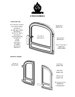
Страница 16: ... Door Handle Black HCE05 053 Handle Spacer Black HCE05 054 Handle Nut Black HCE05 055 Shaft Door Handle HCE05 038 Circlip FLRX07 M8 Full Nut FSHM08 Door Catch HMS04 037 STOVE SPARES SINGLE DOOR DOUBLE DOORS R H Door HMS04 004 Door Glass HMS04 054 Glass Gasket HMS04 056 Glass Clip Screw HHR08 046 FSJM05008SS L H Door HMS04 006 ...

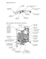
Страница 17: ...75 Side Bricks HCE06 020 Recouping Baffle HCE06 044 Riddling Bars Lower CNS06 001 6 Upper CNS06 002 5 Riddling Support HCE05 065 Cast Iron Inner Base HCE05 042M Ashpan HCE05 011 Cast Iron Side Plates L H HCE05 044 R H HCE05 045 Cam Bar HCE06 010 Cam Hole Plate HCE06 030 Slider Knob HCE06 059 Washer x3 FWFM06016 Support HCE06 046 Shaft HCE06 048 Spacer Primary Air Valve x3 HCE06 049 Primary Air Val...

Страница 18: ... Nut FNLM12Z Catch Shaft HCE05 082 Catch End HCE09 089 Catch Spacer HCE05 081S 4mm x 14mm Roll Pin FPGM04014 Catch Barrel HCE09 091 Catch Collar HCE09 092S M3 Ball Bearing FBBM03C Snap Ring FLRWM0160 M6 Socket Set Screw FSGM06006CP QUARTER TURN DOOR HANDLE DOUBLE DOOR MULTIFUEL PARTS ...

Отзывы: