Clarke Weld 215TE Скачать руководство пользователя страница 9

17

LOADING WIRE

NOTE:

 These machines are designed to accept either 5Kg or 15Kg wire spools of

mild steel, stainless steel or aluminium according to the type of metal you wish to
weld. Wire spools ARE NOT supplied with the unit and must be purchased separately.

1 Ensure the gas and electrical supplies are disconnected;
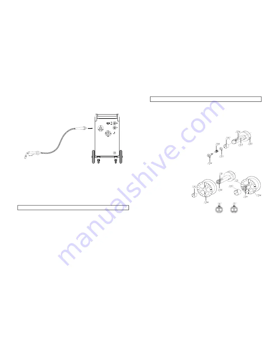
2 (Ref. Fig. 3) Turn the plastic knob (23F), 180°.

3 Take off the plastic cover of the wire spool;

FIG.3

4 To fit the wire spool (23H)

into the hub (23A) push the
button  (23I), insert the wire
spool, followed by the collar
(23C)(it must be used only
with 5Kg wire spools) .

5 Turn  the plastic knob (23F)

by 180° again.

6 Loosen the plastic knob   by

turning it anti-clockwise,
(this maintains pressure on
the wire via the roller). Pull,
on the plastic knob, so that
the screw rod comes out
of its slot, thereby
releasing the pivoted roller
bracket. Raise the bracket
together with the pressure
roller, and pullout any wire
that has been left in the
hose.

7    If you are changing the size of wire, you must also select the appropriate groove

on the feed roller. To change to the other groove, undo the Hex. Socket Screw and
remove the roller from its shaft. Turn it through 180°, replace it on the shaft, and
adjust so that the groove is directly in line with the Wire Liner. Firmly secure it in
that position with the Hex. Socket Screw.

8   Clip the end of the wire, on the spool, cleanly, ensuring there are no burrs or sharp

edges, and, ensuring it is straight, feed it through the guide tube , over the channel
on the roller  and into the wire liner, by approx. 10 - 15cm.

FACE MASK

To assemble the face mask, first place the dark glass window and the clear glass
window together in the recessed window area of the body.

IMPORTANT: the clear glass window should be placed on the outside of the
mask.

Secure in place using the screws and nuts provided. Bend the sides of the mask into
shape and fix together using the screws and nuts provided, and finally, fit the handle
to the shield body also using the screws and nuts provided.

ATTACHING THE GAS BOTTLE AND REGULATOR

1.

The bottle (not supplied) should be located at the rear of the welder,
securely held in position by the chain provided.

2.

For safety, and economy, ensure that the regulator is fully closed, (turned
anti-clockwise) when not welding and when fitting or removing  the gas cylinder.

3.

Connect the gas hose to the regulator securing with clip/nut provided.

4.

Screw the gas regulator fully down on the gas bottle valve, and fully tighten.

5.

Turn the power on, open the cylinder valve, then set the gas flow to approx. 8l/
min. on the regulator. Operate the torch trigger to ensure that the gas is flowing
through the torch.

TORCH LEAD ASSEMBLY INSTRUCTIONS

Plug the troch hose into the socket on the front of the welder and secure by hand
screwing in the threaded connection.

 FIG.2

Содержание Weld 215TE

Страница 1: ...1 Model Nos 215TE 250TE 260TE OPERATING MAINTENANCE INSTRUCTIONS 0100...

Страница 2: ...not used for the purpose for which it was intended Faulty goods should be returned to their place of purchase no product can be returned to us without prior permission This guarantee does not effect y...

Страница 3: ...of manufacture to ensure that your Clarke Mig Welder arrives with you in good condition Before using the machine it is in your own interest to read this manual thoroughly paying particular attention...

Страница 4: ...oxic fumes should not be heated unless coating is removed from the work surface the area is well ventilated or the operator wears an air supplied respirator Work in a confined space only while it is b...

Страница 5: ...circuits BE AWARE THAT flying sparks or falling slag can pass through cracks along pipes through windows or doors and through wall or floor openings out of sight of the goggled operator Sparks and sla...

Страница 6: ...2 C Equipment s rated capacity Do not overload arc welding equipment It may overheat cables and cause a fire Loose cable connections may overheat or flash and cause a fire Never strike an arc on a cy...

Страница 7: ...l adhering to the pieces to be welded oils paints tars which may cause annoyance to the operator Avoid welding by contact with humid parts nearby combustible liquids Least of all do not weld upon tank...

Страница 8: ...le 1Ph 230 volt 50Hz A 13 Amp plug is not suitable for this device Connect the three core mains lead to a suitably fused supply through an isolator or heavy duty plug IMPORTANT The wires in the mains...

Страница 9: ...ex Socket Screw 8 Clip the end of the wire on the spool cleanly ensuring there are no burrs or sharp edges and ensuring it is straight feed it through the guide tube over the channel on the roller and...

Страница 10: ...GH HIGH HIGH 9 Reposition the pressure roller and plastic knob and tighten slightly IMPORTANT Too tight will crush the wire and damage the wire feed motor too loose will not allow the wire to be pulle...

Страница 11: ...Rusty dirty wire e Poor earth contact a Check that gas is not being blown away by draughts if so move to a sheltered area If no draught incrtease gas supply b C o nsult your Mig Welding manual c Ensu...

Страница 12: ...T 1 6m m DOUBLE VEE BUTT JOINT NOT LESS THAN 70 NOT LESS THAN 70 SINGLE BEVEL JOINT DOUBLE BEVEL JOINT CORNER JOINT SINGLE FILLET LAP JOINT DOUBLE FILLET LAP JOINT SINGLE STRAP JOINT DOUBLE STRAP JOIN...

Страница 13: ...R 1 25 EM33805021 WIRE FEED ROLL 0 8 1MM NYLON AL MOTOR 2R 1 25 EM33805022 WIRE FEED ROLL 1 2 1 6MM NYLON MOT AL 2R 1 26 EM21625002 RUBBERPIVOTINGWHEELD 80 2 27 EM33710134 FRONTPANEL 1 28 EM21500004 B...

Страница 14: ...R 2R 1 25 EM33805005 WIRE FEED ROLL 1 0 1 2MM AL MOTOR 2R 1 25 EM33805021 WIRE FEED ROLL 0 8 1MM NYLON AL MOTOR 2R 1 25 EM33805022 WIRE FEED ROLL 1 2 1 6MM NYLON MOT AL 2R 1 26 EM21625002 RUBBERPIVOTI...

Страница 15: ...8MM AL MOTOR 2R 1 23 EM33805005 WIRE FEED ROLL 1 0 1 2MM AL MOTOR 2R 1 23 EM33805021 WIRE FEED ROLL 0 8 1MM NYLON AL MOTOR 2R 1 23 EM33805022 WIRE FEED ROLL 1 2 1 6MM NYLON MOT AL 2R 1 24 EM22225007 C...

Страница 16: ...31 WIRING DIAGRAM MIG 260TE Part No 6010390...

Страница 17: ......

Отзывы: