


21
TROUBLE SHOOTING
Your Clarke Mig Welder has been designed to give long and trouble free service. If,
however, having followed the instructions in this booklet carefully, you still encounter
problems, the following points should help identify and resolve them.
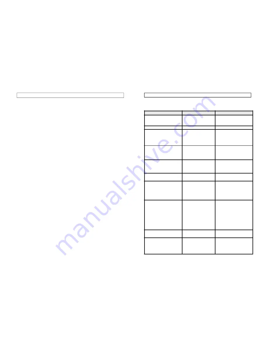
PROBLEM
PROBABLE CAUSE
POSSIBLE SOLUTION
1. No "life" from the welder
Check fuses and mains lead.
a) Replace fuses as necessary. If
problem persists, return welder to
your local dealer.
b) Check fuse size.
2. No wire feed
Motor malfunction
Return welder to your local dealer.
3. Feed motor operates but wire
will not feed
a ) i n s u f f i c i e n t f e e d r o l l e r
pressure
b) Burr on end of wire
c) Linerblocked or damaged
d) Inferior wire
a) Increase roller pressure
b) Re-cut wire square
c) Clear with compressed air or
replace liner.
d) Use only good clean wire
4. Wire welds itself to tip
a) Wire feed speed too low
b) Wrong size tip
a) Unscrew tip, cut wire and
fitnew tip. Increase wire speed
before operating again.
b) Change tip size.
5. Wire feeds into "bird's" nest
tangle.
a) Wire welded to tip.
b ) W i r e l i n e r d a m a g e d
preventing smooth operation.
a) As above plus reduce feedroller
pressure so that if blockage occurs
wire sleeps on roller. i.e. no feed
b) Renew wire liner.
6. Loose coils of wire
tanglearound wire druminside
machine
Drum brake too slack.
Tighten drum brake - DO NOT
OVERTIGHTEN
7. Erratic wire feed
a) Drum brake too tight
b) Feed roller worn
c) Insufficient pressure on
feed roller
d) Wire dirty, rusty, damp or
bent
d) Liner partilly blocked
a) Loosen drum brake slightly
b) Checkand replace if necessary
c) Increase pressur eon feed roller
DO NOT OVERTIGHTEN
d ) Re-cut wire and ensure it i s
clean
e) Clear with compressed air
8. Poor quality welds
a) Insufficient gas at weld area
b ) I n c o r r e c t g a s / w i r e
combination
c) Rusty, painted, damp, oily or
greasy workpiece
d) Rusty, dirty wire.
e) Poor earth contact
a ) Check that gas is not being
b lown a w a y b y draughts, i f s o ,
m o ve to a sheltered area. If no
draught, incrtease gas supply.
b ) C o n s u l t y o u r M i g W e l d i n g
manual
c) Ensure workpiece is clean and
dry
d) Ensure wire is clean and dry
e) Check ground clamp/workpiece
connection.
9. Wire jams in tip when welding
aluminium
Tip too small
Use slightlyoversize tip i.e. fo r
0.8mm wire use 1mm tip (Applies
to aluminium only)
10.Welder cuts out whilst in use
Duty cycle exceeded (auto
cut-out operates)
Allow welder to cool for 15-30min.
before continuing. Note if duty
cycle is continually e x c e e d e d ,
damage to the welder may result
and welder output is probably too
small for application.
WELDING HINTS AND MAINTENANCE
1
Always weld clean, dry and well prepared material.
2
Hold gun at a 45° angle to the workpiece with nozzle about 6mm from the
surface.
3
Move the gun smoothly and steadily as you weld.
4
Avoid welding in very draughty areas. A weak pitted and porous weld will
result due to air blowing away the protective welding gas.
5
Keep wire and wire liner clean. Do not use rusted wire.
6
Sharp bends or kinks on the welding hose should be avoided.
7
Always try to avoid getting particles of metal inside the machine since they
could cause short circuits.
8
If available, use compressed air to periodically clean the hose liner when
changing wire spools
IMPORTANT: Disconnect from power source when carrying out this operation.
9
Using low pressure air (20-30 PSI), occasionally blow the dust from the inside
of the welder. This keeps the machine running cooler. Note: do not blow air
over the printed circuit board and electronic components.
10
The wire feed roller will eventually wear during normal use. With the correct
tension the pressure roller must feed the wire without slipping. If the pressure
roller and the wire feed roller make contact (when the wire is in place between
them), the wire feed roller must be replaced.
11
Check all cables periodically. They must be in good condition and not cracked.
Содержание Weld 215TE
Страница 1: ...1 Model Nos 215TE 250TE 260TE OPERATING MAINTENANCE INSTRUCTIONS 0100...
Страница 16: ...31 WIRING DIAGRAM MIG 260TE Part No 6010390...
Страница 17: ......


