


9
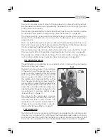
THE HEADSTOCK
The motor provides a direct drive to the Spindle via an internal tooth type belt.
Spindle speed is variable, and is regulated by the Speed Control Knob (23), located
on the main control panel.
The spindle, is provided with an internal No.3 Morse taper to accommodate a centre
for use with a face plate or turning clamp, (See ‘Accessories’ on page 24).
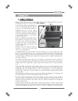
The Chuck Guard (3), is an essential component and is mounted on a pin which is
secured to the headstock by two screws. This should always be in place when
using a chuck.
The 3-Jaw, Self Centering Chuck (4) is mounted on the Spindle Flange (2). To remove
the chuck, simply remove the three securing nuts to the rear of the flange allowing
it to be pulled free together with the three mounting studs.
Three external jaws are also supplied which extend the capacity of the chuck.
Their uses and method of assembly is described under ‘Accessories’ on page 24.
The spindle has 6 holes drilled in its flange to accommodate a range of fixtures
such as a Face Plate, 4-Jaw chuck etc., (See ‘Accessories’ on page 24).
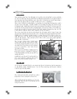
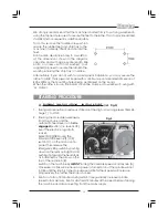
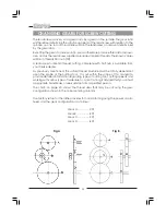
THE RUNNING GEAR
The Running Gear, is protected by a cover (22), which is removed by unscrewing
the two securing hex. screws.
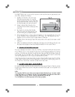
The gear train, shown in Fig. 2, transmits drive
to the lead screw. The Lead Screw acts as
a worm and by operating the Auto Feed
Lever (15), which engages a nut with the
lead screw (worm), drive is transmitted to
the saddle, and consequently the cutting
tool, thereby providing a power feed for
screw cutting or general turning operations.
The rotational speed of the lead screw, and
hence the rate of feed of the cutting tool,
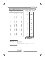
is determined by the gear configuration. This
is explained in greater detail under
‘Screwcutting’ on page 17.
The drive to the leadscrew may be
disconnected by operating the lever (27),
and the same lever is used to drive the
leadscrew in a forward or reverse direction.
(These actions are described in greater
detail under ‘Screwcutting’ on page 17.
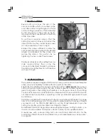
THE TAILSTOCK
The Tailstock (9), may be moved along the bed to any desired position and is secured
in position by a single nut (10), at its base. The Tailstock Spindle carries an internal
No.2 Morse taper for use with the Centre (8) provided. A Revolving Centre and Drill
Chuck are also available from your Clarke dealer. (See Accessories on page23).
Fig 2
27
26
Содержание MetalWorker CL300M
Страница 1: ...1 OPERATING MAINTENANCE INSTRUCTIONS 300mm VARIABLE SPEED METAL LATHE Model No CL300M 1008...
Страница 4: ...4...
Страница 29: ...29 PARTS DIAGRAM...
Страница 30: ...30 WIRING DIAGRAM...
Страница 31: ...31 NOTES...
Страница 32: ...32...