


19
The general procedure for screwcutting is as follows:
1.
Try to get as much distance from the chuck to the end of the proposed screw
thread as possible, and if your design allows, cut a ‘run-off’ into the work which
is of a smaller diameter than the root diameter of the proposed screw thread.
Note, that for long threads it may be necessary to use ‘steady’s’ (see
‘Accessories’ on page 24).
2.
Install the appropriate gears for the thread required, and correctly mount the
cutting tool.
Set your required depth of cut, and position the tool ready to begin cutting.
NOTE: Depth of cut is vitally important and may be calculated or obtained from an
appropriate reference manual.
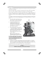
3.
Take all necessary precautions previously stated, and start the machine with
the automatic feed lever in its’
disengaged
position (UP).
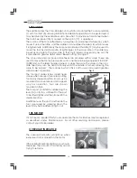
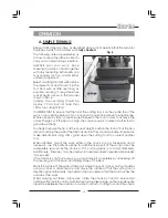
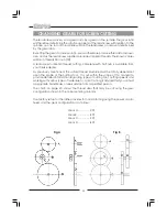
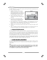
NOTE: Mounted on the Apron, adjacent to the Auto Feed
Lever, is the Thread Dial Indicator, shown in fig. 10.
This is permanently connected to the leadscrew and
as the leadscrew turns,the ‘dial’ spins. Eight radial
marks are etched on the dial and these are used to
determine the exact position of the leadscrew thread
in relation to the saddle.
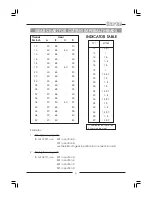
Mounted on the front of the gear train cover is the
Indicator Table, which is duplicated on page 20.
The numbers in the ‘SCALE’ column refer to the
numbers on the radial lines on the Indicator Dial.
Therefore, if a 20TPI thread is to be cut for example,
the marks 1,3,5 or 7 may be used. You should now
procede as follows:
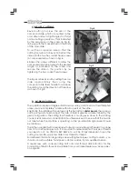
4.
Observe the spinning Dial. In particular, concentrate on one of the numbered
marks etched on the dial which corresponds to the scale number given in the
Indicator Table.
(In our example, this could be 1,3, 5 or 7)
As your line line passes the mark on the body of the dial indicator, engage the
auto lever sharply and thread cutting will commence.
5.
As the tool approaches the end of the desired thread, DISENGAGE THE AUTO
FEED LEVER. Do not switch the machine OFF.
6.
Retract the tool, using the cross-slide feed handle, noting the exact position on
the scale and the exact number of turns.
Wind the saddle back to the begining and reset the tool by winding IN the
cross-slide the exact number of turns previously wound OUT and then continue
to wind IN to the desired depth of cut.
7.
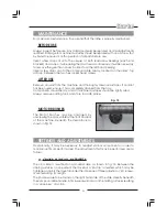
With the machine still running, observe the dial indicator and as
the same
numbered line,
passes the mark on the body, engage the auto feed lever once
again. Proceed in this manner until the thread is completed.
Engaging the auto feed lever as your predetermined line on the dial passes the
mark on the body ensures the half nuts of the auto feed mechanism engage in
the same thread on the leadscrew each time, thereby ensuring the cutting
tool is in the same place for each pass which in turn produces a perfect thread.
Fig 10
Содержание MetalWorker CL300M
Страница 1: ...1 OPERATING MAINTENANCE INSTRUCTIONS 300mm VARIABLE SPEED METAL LATHE Model No CL300M 1008...
Страница 4: ...4...
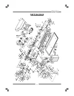
Страница 29: ...29 PARTS DIAGRAM...
Страница 30: ...30 WIRING DIAGRAM...
Страница 31: ...31 NOTES...
Страница 32: ...32...