Clarke MetalWorker CL300M Скачать руководство пользователя страница 15

15

OPERATION

A. SIMPLE TURNING

Before starting the machine, as described above, it is imperative that the setup for
the type of work to be carried out is 

fully checked

.

The following notes are guidelines as
to how to set up the lathe in order to
carry out a simple turning operation.

ALWAYS plan your work. Have
drawings or a plan on hand together
with any measuring instruments you
may require, such as micrometers/
verniers/calipers etc.

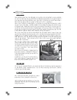
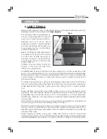
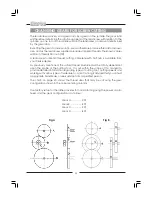
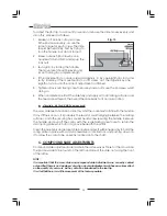
Select a cutting tool that will produce
the desired cut and mount it in the
Tool Rest, with as little overhang as
possible, securing it using three hex
socket head screws in the manner
shown in FIG. 6.
(Ideally, the overhang should be
approx. 10 mm but not more than
15mm for a straight tool).

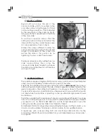
It is IMPORTANT to ensure that the tip of the cutting tool is on the centre line of the
work, or very slightly below it. On no account should it be above the centre line.
Where necessary shims should be used beneath the tool in order to achieve the
correct height, or, if the tip is too high, the only recourse is to select another tool or
grind down the tip.

To check to ensure the tip is at the correct height, position the tool so that the tip is
almost touching the point of the tailstock centre. They should coincide. If necessary
make adjustments using shims, grind down the cutting tool tip or select another
tool.

When satisfied, mount the work, either in the chuck or on a faceplate, and if
necessary, use the tailstock centre for additional support (If the work cannot be
adequately secured by the chuck, or if it is a long piece, or of small diameter).
Additionally, ‘Steadies’ may be used which are described in greater detail under
‘Accessories’.
If the Tailstock is not to be used, you may remove it completely by slackening off
the securing nut at its base, and sliding it free of the bed.

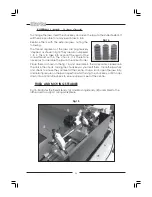
Mark the surface of the work at the point where the cut is to end, i.e. the shoulder,
using a scriber or similar means, and move the saddle so that the cutting tool is
directly opposite the mark, then wind in the cross-slide so that the tool touches the
surface of the work.
Whilst carrying out these manouvres, rotate the chuck by hand to ensure that
nothing will come into contact with it when turning takes place, i.e. there is adequate
clearance between the saddle, cross-slide, tool post or cutting tool, and the chuck.

Fig 6

Содержание MetalWorker CL300M

Страница 1: ...1 OPERATING MAINTENANCE INSTRUCTIONS 300mm VARIABLE SPEED METAL LATHE Model No CL300M 1008...

Страница 2: ...820x295x300mm Weight 40kg Screw Threads Imperial 12 104 TPI in 26 steps Metric 0 4 2 0mm pitch in 10 steps For Spare Parts and Servicing please contact your nearest dealer or CLARKE International on o...

Страница 3: ...Motor 10 Unpacking and Preparing for Use 11 Installation Electrical Connections 12 Mounting the Lathe 12 Starting Procedure 13 Operation Simple Turning 15 Using Power Feed 17 Bevel Cutting 18 Screw C...

Страница 4: ...4...

Страница 5: ...rouble free service from your Clarke Metal Lathe GUARANTEE This product is guaranteed against faults in manufacture for 12 months from date of purchase Please keep your receipt as it will be required...

Страница 6: ...keys 8 KEEP CHILDREN AND VISITORS AWAY All children and visitors should be kept a safe distance from work area 9 DON T FORCE THE MACHINE It will do the job better and safer at the rate for which it wa...

Страница 7: ...fied person 2 Do not operate the machine until it is completely assembled and this entire manual has been read and understood 3 Ensure the proper electrical regulations are followed and that the machi...

Страница 8: ...l Indicator Table 8 Tailstock Centre 22 Running Gear Cover 9 Tailstock 23 Variable Speed Control Knob 10 Tailstock Securing Nut 24 Forward Off Reverse Switch 11 Bed 25 Emergency Stop Switch 12 R H Lea...

Страница 9: ...n page 24 THE RUNNING GEAR The Running Gear is protected by a cover 22 which is removed by unscrewing the two securing hex screws The gear train shown in Fig 2 transmits drive to the lead screw The Le...

Страница 10: ...quivalent to 0 001 0 025mm As the feed handle is turned so does the scale The scale on the cross slide feed may also be held stationary whilst the handle is turned allowing the scale to be zeroed The...

Страница 11: ...ay round Then turn all feed handles to ensure they are free and move evenly and smoothly Attach the plastic handles to the rims of the manual feed and tailstock feed handwheels respectively ensuring t...

Страница 12: ...rminal marked with a letter N or coloured BLACK If this appliance is fitted with a plug which is moulded onto the electric cable i e non wirable please note 1 The plug must be thrown away if it is cut...

Страница 13: ...amps STARTING PROCEDURE A DURING INSTALLATION INITIAL START ref Fig 5 1 Taking all precautions previously stated set the High Low range lever item 26 page 7 to LOW 2 Ensuring the cross slide is well a...

Страница 14: ...the Auto Feed lever is dis engaged depending upon whether or not automatic feed is required IMPORTANT This should ALWAYS be a deliberate conscious action NOTE If Auto feed is required the Leadscrew F...

Страница 15: ...d down the tip To check to ensure the tip is at the correct height position the tool so that the tip is almost touching the point of the tailstock centre They should coincide If necessary make adjustm...

Страница 16: ...ide or compound slide ALWAYS use this procedure to align the marks This is to take into account backlash and other clearances in the gearing and slides etc Continue to turn the handle an amount equiva...

Страница 17: ...set on the cross slide 2 Ensure the leadscrew F N R lever is set to Forward and select Forward on the Forward Off Reverse switch on the main control panel Release the Emergency Stop and switch ON the...

Страница 18: ...ttempted unless you are completely familiar with all aspects of the lathe Essentially the saddle will move towards the headstock under power the same as cutting using auto feed except the rate of feed...

Страница 19: ...o the numbers on the radial lines on the Indicator Dial Therefore if a 20TPI thread is to be cut for example the marks 1 3 5 or 7 may be used You should now procede as follows 4 Observe the spinning D...

Страница 20: ...half nuts is available from your Clarke dealer As previously mentioned the actual thread produced will be totally dependant upon the profile of the cutting tool It is not within the scope of this manu...

Страница 21: ...AL THREADS Examples 1 Ref Fig A on page 19 To cut 12 TPI use 40T in position A 30T in position D use the 65 tooth gear in position B to connect A and D 2 Ref Fig B on page 19 To cut 38 TPI use 20T in...

Страница 22: ...for easier reassembly unscrew the nut securing the shaft carrying B and C and the nut securing the adjuster A 3 Remove the gears taking care to retain the small keys on each shaft and replace with tho...

Страница 23: ...mpletely drained from the tray Components should be dry and all machined surfaces should be lightly oiled Always remove cutting tools and store in a safe place MOTOR BRUSHES The Motor brushes may be c...

Страница 24: ...E The cross slide feed should run smoothly and the scale must rotate with the handle If any stiffness occurs it is probably the result of swarf lodging between the mating surfaces Undo the securing he...

Страница 25: ...723 3 Moving Steady 7610724 4 Fixed Steady 7610722 5 Tailstock Drilling Chuck with a 30mm capacity 7610725 6 Headstock Centre MT3 7610726 7 Revolving Centre Tailstock MT2 7610727 8 6 Piece Cutting Too...

Страница 26: ...is therefore necessary to assemble the jaws in the correct order Place them as shown in the fig 14 and assemble in the same order clockwise in the slots in the chuck turning the chuck key as you inser...

Страница 27: ...Mount 1 HT300M036 37 Spring 1 HT300M037 38 Indicator 1 HT300M038 39 Pinion 25T 1 HT300M039 40 Support Screw 2 HT300M040 No Description Qty Part No 41 Pinion 20T 1 HT300M041 42 Fixed Cover 1 HT300M042...

Страница 28: ...bber Foot 4 HT300M125 126 Chip Tray 1 HT300M126 127 Bracket 1 HT300M127 128 Key M3x16 1 HT300M128 129 Lead Screw Imperial 1 HT300M129 131 Bracket 1 HT300M131 132 Plastic Plug 1 HT300M132 133 Screw M4x...

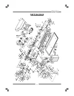
Страница 29: ...29 PARTS DIAGRAM...

Страница 30: ...30 WIRING DIAGRAM...

Страница 31: ...31 NOTES...

Страница 32: ...32...

Отзывы: