


26
Fig 15
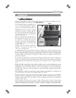
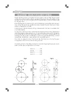
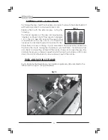
EXTERNAL JAWS - 3-Jaw Chuck
To change the jaws, insert the chuck key and open the jaws to their fullest extent. It
will then be possible to remove each jaw in turn.
Replace them with the external jaws, noting the
following.
The thread segments of the jaws are progressively
‘stepped’ as shown in fig 14. They are also numbered
1 to 3. This is to take into account the lead of the
screwthread within the chuck. It is therefore
necessary to assemble the jaws in the correct order.
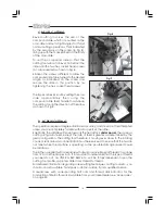
Place them as shown in the fig. 14, and assemble in the same order, clockwise in
the slots in the chuck, turning the chuck key as you insert them. Close the jaws fully
and check to ensure they all meet at the centre. If a jaw is out, open the jaws fully,
and retain pressure on the jaw in question whist turning the chuck key, until it snaps
down into position. Re-check to ensure all jaws meet at the centre.
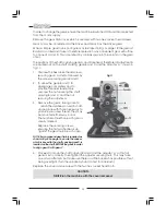
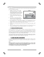
FIXED AND MOVING STEADIES
Fig 15, illustrates the Fixed Steady (A) and Movong Steady (B) assembled to the
lathe, used to support a long workpiece
Fig.14
Содержание MetalWorker CL300M
Страница 1: ...1 OPERATING MAINTENANCE INSTRUCTIONS 300mm VARIABLE SPEED METAL LATHE Model No CL300M 1008...
Страница 4: ...4...
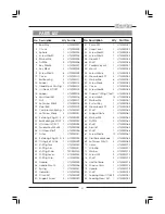
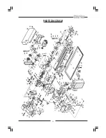
Страница 29: ...29 PARTS DIAGRAM...
Страница 30: ...30 WIRING DIAGRAM...
Страница 31: ...31 NOTES...
Страница 32: ...32...