


27
No. Description
Qty Part No.
1 Bed Way
1
HT300M001
2 Chuck
1
HT300M002
3 Spindle
1
HT300M003
4 Screw M6x30
3
HT300M004
5 Washer M6
3
HT300M005
6 Nut M6
5
HT300M006
7 Key M5x35
1
HT300M007
8 Key M4x8
2
HT300M008
9 Screw M5x10
6
HT300M009
10 Cover
2
HT300M010
11 Ball Bearing
2
HT300M011
12 Spacer
2
HT300M012
13 Head Stock Casting
1
HT300M013
14 H/l Gear 21T/29T
1
HT300M014
15 Spacer
1
HT300M015
16 Spur Gear 45T
1
HT300M016
17 Nut
1
HT300M017
18 Set Screw M5x8
1
HT300M018
19 Steel Ball
2
HT300M019
20 Compression Spring
3
HT300M020
21 Set Screw M6x6
3
HT300M021
22 Retaining Ring M12
2
HT300M022
23 Ball Bearings 6201ZZ
2
HT300M023
24 H/L Gear 12T/20T
1
HT300M024
25 Parellel Key M4x45
1
HT300M025
26 H/L Gear Shaft
1
HT300M026
27 Pulley
1
HT300M027
28 Retaining Ring M10
2
HT300M028
29 Timing Belt Lx136
1
HT300M029
30 Shifting Fork
1
HT300M030
31 Shifting Arm
1
HT300M031
32 Shifting Knob
1
T300M0032
33 Shifting Lever
1
HT300M033
34 Shifting Grip
1
HT300M034
35 Handle
1
HT300M035
36 Handle Mount
1
HT300M036
37 Spring
1
HT300M037
38 Indicator
1
HT300M038
39 Pinion 25T
1
HT300M039
40 Support Screw
2
HT300M040
No. Description
Qty
Part No.
41 Pinion 20T
1
HT300M041
42 Fixed Cover
1
HT300M042
43 Screw M6x20
2
HT300M043
44 Screw M5x10
1
HT300M044
45 Gear 45T
1
HT300M045
46 Shaft
1
HT300M046
47 Parallel Key 3x8
1
HT300M047
48 Mount
1
HT300M048
49 Screw M5x16
2
HT300M049
50 Gearwheel 20T
2
HT300M050
51 Washer M6
6
HT300M051
52 Screw M6x6
4
HT300M052
53 Cover
1
HT300M053
54 Screw M6x45
2
HT300M054
55 Thread Cutting Chart 1
HT300M055
56 Screw M5x8
12
HT300M056
57 Washer M4
2
HT300M057
58 Bush w/Key
1
HT300M058
59 Gearwheel 80T
2
HT300M059
60 Shaft
1
HT300M060
61 Support Plate
1
HT300M061
62 Washer M8
3
HT300M062
63 Nut M8
3
HT300M063
64 Shaft
1
HT300M064
65 Dial 16T
1
HT300M065
66 Shaft
1
HT300M066
67 Screw M6x16
10
HT300M067
68 Dial Indicator Body
1
HT300M068
69 Set Screw M4x10
3
HT300M069
70 Apron
1
HT300M070
71 Gib Strip
1
HT300M071
72 Washer
2
HT300M072
73 Screw M4
2
HT300M073
74 Shaft
2
HT300M074
75 Half Nut Base
2
HT300M075
78 Groove Cam
1
HT300M078
79 Handle
1
HT300M079
80 Shaft
1
HT300M080
81 Feeding Gear 11T/54T1
HT300M081
82 Feeding Gear 24T
1
HT300M082
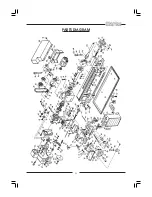
PARTS LIST
Содержание MetalWorker CL300M
Страница 1: ...1 OPERATING MAINTENANCE INSTRUCTIONS 300mm VARIABLE SPEED METAL LATHE Model No CL300M 1008...
Страница 4: ...4...
Страница 29: ...29 PARTS DIAGRAM...
Страница 30: ...30 WIRING DIAGRAM...
Страница 31: ...31 NOTES...
Страница 32: ...32...