iDP3240 SERVICE MANUAL
8
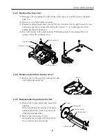
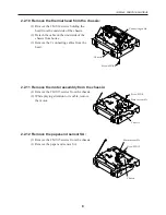
2.2.10 Remove the thermal head from the chassis:
(1) Remove the 2 M3
×
4 screws holding the
head from the underside of the chassis.
(2) Detach the cable on the underside of the
chassis from hooks.
(3) Remove the 2 connecting cables from the
head.
2.2.11 Remove the motor assembly from the chassis:
(1) Remove the 2 M3
×
5 screws from the chassis.
(2) While playing attention to its cable, remove
the motor.
2.2.12 Remove the paper-end sensor SA:
(1) Remove the 2 M3
×
5 screws from the chassis.
(1) Remove the paper-end sensor SA.
Screw M3
×
5
Motor assembly
Chassis
Connecting cable
Chassis
Screw M3
×
4
Screw M3
×
5
Motor assembly
Chassis
Содержание iDP3240
Страница 1: ...LINE THERMAL PRINTER MODEL iDP3240 Rev 1 0 First created Feb 10th 2000 Service Manual...
Страница 2: ...i REVISION Rev No Date Content Rev 1 0 Feb 10th 2000 First created...
Страница 16: ...iDP3240 SERVICE MANUAL 13 3 2 Exploded View 2 5 4 3 71 31 30 29 28 45 44 43 41 52 51 50 49 48...
Страница 23: ...iDP3240 SERVICE MANUAL 20 4 3 2 Control PCB Assy Reverse side of the board...
Страница 24: ...iDP3240 SERVICE MANUAL 21 4 3 3 Control PCB Assy Top side of the board Parallel Interface...
Страница 25: ...iDP3240 SERVICE MANUAL 22 4 3 4 Control PCB Assy Reverse side of the board...
Страница 33: ...iDP3240 SERVICE MANUAL 30 6 OUTLINE DRAWING FEED ERROR POWER 9 37 201 119 5 186 123...


