iDP3240 SERVICE MANUAL
7
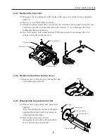
2.2.6 Remove the pressure roller:
(1) Remove the 2 M2.6
×
6 Screws from
the printer cover.
(2) Bend the roller spring to remove it
from the roller holder.
(3) Bend the roller holder’s bearing
section to remove the roller.
2.2.7 Remove the bottom cover:
(1) Remove the 2 M3
×
8 screws located in the
lower part of the bottom cover.
(2) Lifting the back of the bottom cover, remove it.
2.2.8 Remove the Auto Cutter ACS-241
from the chassis:
(1) Disconnect the connector for the cutter
connected to the control board.
(2) Remove the 2 M2.6
×
6 screws and lift the
ACS-241 upwards to remove.
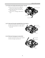
2.2.9 Remove the control board from the chassis:
(1) Remove all connecting cables on the board.
(2) Remove the 3 M3
×
8 screws.
(3) While taking special care not to deform or
damage the paper-near-end sensor and power
switch, etc, lift the chassis straight up.
ACS-241
Screw M2.6
×
6
Bottom cover
Control board
Screw M3
×
8
Chassis
Roller
Roller holder
Pan head screw M2.6
×
6
Roller spring
Printer cover
Содержание iDP3240
Страница 1: ...LINE THERMAL PRINTER MODEL iDP3240 Rev 1 0 First created Feb 10th 2000 Service Manual...
Страница 2: ...i REVISION Rev No Date Content Rev 1 0 Feb 10th 2000 First created...
Страница 16: ...iDP3240 SERVICE MANUAL 13 3 2 Exploded View 2 5 4 3 71 31 30 29 28 45 44 43 41 52 51 50 49 48...
Страница 23: ...iDP3240 SERVICE MANUAL 20 4 3 2 Control PCB Assy Reverse side of the board...
Страница 24: ...iDP3240 SERVICE MANUAL 21 4 3 3 Control PCB Assy Top side of the board Parallel Interface...
Страница 25: ...iDP3240 SERVICE MANUAL 22 4 3 4 Control PCB Assy Reverse side of the board...
Страница 33: ...iDP3240 SERVICE MANUAL 30 6 OUTLINE DRAWING FEED ERROR POWER 9 37 201 119 5 186 123...


