background image

iDP3240  SERVICE  MANUAL

4

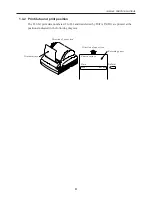
1.4.2 Print data and print position

The 832-bit print data numbered 1 to 832 and transferred by DATA IN (DI) are printed at the
positions indicated in the following diagram.

Recording paper

Direction of paper feed

Printed surface

Printed surface

Direction of paper feed

Data

DATA IN

1234  ·  ·  ·  ·  ·  ·  ·  ·  · 831 832

Содержание iDP3240

Страница 1: ...LINE THERMAL PRINTER MODEL iDP3240 Rev 1 0 First created Feb 10th 2000 Service Manual...

Страница 2: ...i REVISION Rev No Date Content Rev 1 0 Feb 10th 2000 First created...

Страница 3: ...10 Remove the thermal head from the chassis 8 2 2 11 Remove the motor assembly from the chassis 8 2 2 12 Remove the paper end sensor SA 8 2 2 13 Remove the wire springs from the chassis 9 3 MECHANICA...

Страница 4: ...ia the platen gear to the platen roller and this driving force rotates the platen roller The platen roller is pressed against the surface of the heating unit of the thermal head by wire springs locate...

Страница 5: ...aten roller The platen roller which is a part of the mechanism for feeding recording paper is removable with this printer The platen roller which has the platen gear platen bushings and platen holder...

Страница 6: ...ad is employed as the print head of this printer The thermal head consists of a heat generating unit and a head driver to drive and control the thermal head 1 4 1 Outline of drive control The serial p...

Страница 7: ...n The 832 bit print data numbered 1 to 832 and transferred by DATA IN DI are printed at the positions indicated in the following diagram Recording paper Direction of paper feed Printed surface Printed...

Страница 8: ...e the printer 6 When handling the thermal head do not wear gloves etc likely to generate static electricity 7 When disassembling or assembling inspect cords and boards for damage and be sure not to ro...

Страница 9: ...s indicated by the 2 arrows 1 2 to disengage the claws holding the chassis and the case 4 Return the printer to its normal position While being careful not to damage the wire springs slowly lift out t...

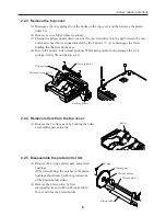
Страница 10: ...it 2 2 8 Remove the Auto Cutter ACS 241 from the chassis 1 Disconnect the connector for the cutter connected to the control board 2 Remove the 2 M2 6 6 screws and lift the ACS 241 upwards to remove 2...

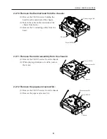
Страница 11: ...Remove the 2 connecting cables from the head 2 2 11 Remove the motor assembly from the chassis 1 Remove the 2 M3 5 screws from the chassis 2 While playing attention to its cable remove the motor 2 2...

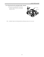
Страница 12: ...e the wire springs from the chassis 1 Raise the wire springs until vertical then push them down with care not to deform them to remove Note Assemble all parts by following the disassembling procedure...

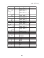
Страница 13: ...70 INSERTER 2 22 E40000360 PE PCB Assy 1 23 E40000370 PE PCB 1 24 E4900 670 CODE Assy CA3 3240 1 25 E391 150 PHOTOINTERRUPTER GP2S40 1 26 E4000390 PE PCB HOLDER 1 27 E62040605 PRINTER COVER Assy 1 28...

Страница 14: ...PN 1 E6100 730 AC CORD SET 2 USA 1 E6100 765 AC CORD SET 3 EUR 1 E5103 560 Switching plug KPR 25 B 59 Rating plate JPN 1 Rating plate USA 1 Rating plate EUR 1 63 PAPER SET LABEL 1 64 CAUTION DON T TOU...

Страница 15: ...iDP3240 SERVICE MANUAL 12 3 2 Exploded View 1 74 59 75 75 73 76 71 70 70 47 65 75 63 39 38 36 35 34 33 26 23 22 20 19 18 17 16 15 14 13 11 10 8 6 2 1 64...

Страница 16: ...iDP3240 SERVICE MANUAL 13 3 2 Exploded View 2 5 4 3 71 31 30 29 28 45 44 43 41 52 51 50 49 48...

Страница 17: ...101 IC101 KANJI ROM 1 1 Only mounted for JPN TA1 TA1 TRANSISTOR ARRAY 1 1 L angle product TA2 TA2 TRANSISTOR ARRAY 1 1 Tr1 9 10 Tr1 9 10 TRANSISTOR 3 3 Tr2 Tr2 TRANSISTOR 1 1 Tr3 4 8 Tr3 4 8 TRANSISTO...

Страница 18: ...8 20 RESISTOR 5 26 30 R11 12 R11 12 RESISTOR 2 2 R1 2 16 RESISTOR 5 21 29 R1 2 16 RESISTOR 5 21 29 R5 7 17 22 25 27 RESISTOR 16 28 35 40 45 50 R5 7 17 22 25 27 RESISTOR 16 28 35 40 45 50 R33 43 R33 43...

Страница 19: ...28 CERAMIC CAPACITOR 5 106 C14 15 C14 15 CERAMIC CAPACITOR 2 2 C17 19 25 CERAMIC CAPACITOR 8 C17 19 25 CERAMIC CAPACITOR 10 27 29 C101 105 CERAMIC CAPACITOR 7 107 108 C101 105 CERAMIC CAPACITOR 7 107...

Страница 20: ...NECTOR 1 1 CN7 CN7 CONNECTOR 1 1 CN8 CN8 CONNECTOR 1 1 CN9 2 CN9 2 CONNECTOR 1 1 CN10 CONNECTOR 1 JPN EUR specifications only CN10 CONNECTOR 1 USA specifications only CN10 CONNECTOR 1 L1 2 4 7 18 32 3...

Страница 21: ...h Cover Switch Paper Near end Paper End Power Source DC 24V 1 8A DC 24V DC 5V Cutter Driver Print Head CPU DIP Switch G A Stepping Motor Driver Driver Drawer1 Parallel Centronics compliant IEEE1284 co...

Страница 22: ...iDP3240 SERVICE MANUAL 19 4 3 Parts Layout Drawing 4 3 1 Control PCB Assy Top side of the board Serial Interface D sub 25 Right angled 3240 01...

Страница 23: ...iDP3240 SERVICE MANUAL 20 4 3 2 Control PCB Assy Reverse side of the board...

Страница 24: ...iDP3240 SERVICE MANUAL 21 4 3 3 Control PCB Assy Top side of the board Parallel Interface...

Страница 25: ...iDP3240 SERVICE MANUAL 22 4 3 4 Control PCB Assy Reverse side of the board...

Страница 26: ...P3240 SERVICE MANUAL 23 4 4 Circuit Diagram 4 4 1 Control PCB Assy Serial Interface D sub 25 Power source Head Motor Cutter Drawer Paper end Photodiode for label Phototransistor for label Paper near e...

Страница 27: ...iDP3240 SERVICE MANUAL 24 4 4 2 Control PCB Assy Parallel Interface Cutter Drawer Paper end Interface Photodiode for label Phototransistor for label Paper near end Power source Head Motor...

Страница 28: ...ame problem check all the relevant items This allows you to pin down concealed defective points Cause Likely causes are listed as far as possible Try to determine the cause of the trouble from the ite...

Страница 29: ...rmal Check Method Check if an out of spec power supply is used Check whether designated fuse is used Use a voltmeter to measure the circuit drive voltage Repair Method Connect the designated AC adapte...

Страница 30: ...pter is used Check the supplied voltage using a tester Check if foreign matter is adhering to the thermal head Check if designated AC adapter is used Check if foreign matter is adhering to the thermal...

Страница 31: ...k the wire springs for deformation or warp Check if the recording paper is jammed torn or trapped in the paper supply path Detach the platen roller and check if foreign matter is trapped in the platen...

Страница 32: ...Method Replace the PE sensor assembly Remove foreign matter Replace the paper near end sensor Connect the connector correctly Remove foreign matter 5 2 4 Faulty sensor Phenomenon The cutter does not o...

Страница 33: ...iDP3240 SERVICE MANUAL 30 6 OUTLINE DRAWING FEED ERROR POWER 9 37 201 119 5 186 123...

Отзывы: