Non-Redundant Mode
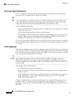
In non-redundant mode, the system may go down with the loss of any supply or power grid associated with
any particular chassis. We do not recommend operating the system in non-redundant mode in a production
environment.
To operate in non-redundant mode, each chassis should have at least two power supplies installed. Supplies
that are not used by the system are placed into standby. The supplies that are placed into standby depends on
the installation order (not on the slot number). The load is balanced across active power supplies, not including
any supplies in standby.
The chassis requires a minimum of 2 power supplies. In cases of low-line operation, the total available power
is 1400W each for a total of 2800W. Do not attempt to run the chassis on less than the minimum number of
power supplies.
Any power supplies that are unused can be put into standby mode, but also not installed in the chassis, if you
choose.
In a non-redundant system, power supplies can be in any slot. Installing less than the required number of
power supplies results in undesired behavior such as compute node shutdown. Installing more than the required
amount of power supplies may result in lower power supply efficiency. At a minimum, this mode will require
two power supplies.
Note
N+1 Power Supply Configuration
In an N+1 configuration, the chassis contains a total number of power supplies to satisfy system power
requirements, plus one additional power supply for redundancy.
In an N+1 configuration, a maximum power of 14kW is delivered with five PSUs configured as Active while
the remaining one PSU is in standby mode. The 14kW maximum delivered power is only possible at high
input voltage range (200-240VAC). In low input voltage range (100-127VAC nominal), the maximum delivered
power would be 7kW.
Note
N+1 configuration is configured when:
• Of the six total PSUs that are participating in N+1 configuration, five are turned on and configured to
operate in Active mode
• All five active PSUs equally share the power load for the chassis.
• The remaining PSU is turned on and configured to provide Standby power to the chassis so that the power
supply can take over operation if one power supply should fail, as long the number of operating power
supplies does not drop below the required minimum.
If one Active power supply should fail, the surviving supplies can provide power to the chassis, until the
Standby power supply can be switched to Active status. In addition, Cisco Intersight turns on any "turned-off"
power supplies to bring the system back to N+1 status. The system will continue to operate, giving you a
chance to replace the failed power supply.
Cisco UCS X9508 Server Chassis Installation Guide
11
Overview
Non-Redundant Mode
Содержание UCS X9508
Страница 6: ...Cisco UCS X9508 Server Chassis Installation Guide vi Contents ...
Страница 26: ...Cisco UCS X9508 Server Chassis Installation Guide 18 Overview Interpreting LEDs ...
Страница 31: ...Cisco UCS X9508 Server Chassis Installation Guide 23 Installation Handling the Chassis ...
Страница 64: ...Cisco UCS X9508 Server Chassis Installation Guide 56 Installation Repacking the Chassis ...
Страница 124: ...Cisco UCS X9508 Server Chassis Installation Guide 116 Technical Specifications Switzerland ...

