background image

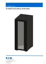
Cisco R42612 Rack and RP-Series Metered Input PDU Installation Guide

First Published:

2016-12-22

Last Modified:

2019-12-13

Americas Headquarters

Cisco Systems, Inc.
170 West Tasman Drive
San Jose, CA 95134-1706
USA
http://www.cisco.com
Tel: 408 526-4000

800 553-NETS (6387)

Fax: 408 527-0883

Содержание R42612 R Series

Страница 1: ... Input PDU Installation Guide First Published 2016 12 22 Last Modified 2019 12 13 Americas Headquarters Cisco Systems Inc 170 West Tasman Drive San Jose CA 95134 1706 USA http www cisco com Tel 408 526 4000 800 553 NETS 6387 Fax 408 527 0883 ...

Страница 2: ...nna Increase the separation between the equipment and receiver Connect the equipment into an outlet on a circuit different from that to which the receiver is connected Consult the dealer or an experienced radio TV technician for help Modifications to this product not authorized by Cisco could void the FCC approval and negate your authority to operate the product The Cisco implementation of TCP hea...

Страница 3: ...s the highest level of reliability structural integrity and security for mission critical environments Features of the Cisco R42612 rack include the following Front and rear doors are perforated to maximize air flow Locks are included for added security The doors also feature tool less removal for convenient servicing Split rear doors minimize the clearance required at the rear of the rack and the...

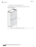
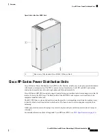
Страница 4: ...ing figures show the front and back of the standard Cisco R42612 R Series rack Figure 1 Front of the Cisco R42612 Rack Front view of the standard Cisco R42612 R Series Rack 1 Cisco R42612 Rack and RP Series Metered Input PDU Installation Guide 2 Overview Cisco R Series Racks ...

Страница 5: ...ws that fit into key holes in the PDU trays The flush profile of the 0RU PDUs also improves serviceability of the equipment installed in the rack The 0RU PDUs have color coded outlet sections that match a corresponding circuit breaker making it easy to identify which circuit breaker feeds which outlet The branch circuit color coding also simplifies load balancing Outlet grip retention ensures that...

Страница 6: ...Cisco R42612 Rack and RP Series Metered Input PDU Installation Guide 4 Overview Cisco RP Series Power Distribution Units ...

Страница 7: ... unit to an unpacking site Moving the unpacked unit to the installation site Select an unpacking location with adequate surrounding space for the unloading process You must allow for the pallet Choose an installation site that can accommodate the Cisco R42612 rack To provide for future installation of a joined configuration you should plan enough space for additional cabinets that occupy the same ...

Страница 8: ... 3 8 or 1 2 flat head screwdriver to lower and raise stabilizers Adjustable wrench for unbolting system Allen wrench to disassemble caster assembly after the unit is sited Standard clippers or knife to cut packaging binding Tape measure Level Anchoring bolts Rotary hammer drill Fork lift Chain hoist Documentation for the devices that you plan to install in the rack Prepare the Subflooring Optional...

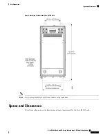
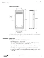
Страница 9: ...bility to fulfill local seismic safety standards Note Space and Clearances The following figure shows the dimensions and space requirements for the Cisco R42612 rack Cisco R42612 Rack and RP Series Metered Input PDU Installation Guide 7 Site Preparation Space and Clearances ...

Страница 10: ...ment as low as possible in the Cisco R4612 rack to maintain a low center of gravity and prevent the Cisco R42612 rack from falling over Use the cable management brackets and straps that are orderable for use with this system to keep cables organized and out of the way of the exhaust fans Make sure that cables do not impair access to other devices or require you to disconnect cables unnecessarily t...

Страница 11: ...hoose your installation site to accommodate existing power sources and network connections Note Whenever you move the Cisco R42612 rack or any heavy object follow these guidelines Always disconnect all external cables before moving the Cisco R Series rack Do not attempt to move the unit by yourself Never attempt to lift an object that might be too heavy for one person to lift alone If you are not ...

Страница 12: ...nditions exist Never assume that power has been disconnected from a circuit always check Do not perform any action that creates a potential hazard to people or makes the equipment unsafe Never install equipment that appears damaged Carefully examine your work area for possible hazards such as moist floors ungrounded power extension cables and missing safety grounds In addition use the following gu...

Страница 13: ...t accidental removal provide proper grounding for the system and help ensure the bus connectors are properly seated Note Follow these guidelines to prevent ESD damage Always use an ESD wrist strap or ankle strap and ensure that it makes good skin contact When handling a removed component make sure the equipment end of you ESD wrist strap is attached to an unfinished chassis surface of the device i...

Страница 14: ...ines for equipment manufacturers and data center designers to standardize on the following issues relating to a data center site Operating environments for classes of equipment Equipment placement for optimum reliability and airflow Tests of performance and the operational health of the data center Equipment installation evaluations Methodology for reporting power cooling and environmental specifi...

Страница 15: ...power source Over voltage under voltage and transients or spikes can erase data from the memory or cause components to fail To protect against these types of problems you should always make sure that the racks that hold the servers or networking devices are grounded When the rack are grounded the equipment installed in them is automatically grounded See the instructions for the products that you i...

Страница 16: ...ompleting before installing a Cisco R42612 rack or PDU Table 2 Site Planning Checklist Date Time Verified By Activity Task No Space evaluation Space and layout Floor covering Impact and vibration Lighting Maintenance access 1 Environmental evaluation Ambient temperature Humidity Altitude Atmospheric contamination Air flow 2 Cisco R42612 Rack and RP Series Metered Input PDU Installation Guide 14 Si...

Страница 17: ...nt power supplies Uninterruptable power supply UPS for power supplies 3 Grounding evaluation Circuit breaker size Ground 4 Cable and interface equipment evaluation Cable type Connector type Cable distance limitations Interface equipment transceivers 5 Electromagnetic interference EMI evaluation Distance limitations for signaling Site wiring Radio frequency interference RFI 6 Cisco R42612 Rack and ...

Страница 18: ...Cisco R42612 Rack and RP Series Metered Input PDU Installation Guide 16 Site Preparation Site Preparation Checklist ...

Страница 19: ...612 rack ships on a wooden pallet with cardboard and plastic covering the rack You will probably need to perform this procedure in the loading dock area of the building A fork lift or chain hoist may be needed Note Remove the Packaging To remove the protective packaging from the Cisco R42612 rack complete the following steps Procedure Step 1 Remove the nylon straps that secure the cardboard sheath...

Страница 20: ...ove the clear plastic that covers the rack and pallet Step 5 Remove the four cardboard corner frames and other packaging material that covers the Cisco R42612 rack Cisco R42612 Rack and RP Series Metered Input PDU Installation Guide 18 Unpacking the Rack Remove the Packaging ...

Страница 21: ...Frames Accessories The accessories that are available for the Cisco R42612 rack include the items listed in the following table Cisco R42612 Rack and RP Series Metered Input PDU Installation Guide 19 Unpacking the Rack Accessories ...

Страница 22: ...ided to ensure your safety This unit should be mounted at the bottom of the rack if it is the only unit in the rack When mounting this unit in a partially filled rack load the rack from the bottom to the top with the heaviest component at the bottom of the rack If the rack is provided with stabilizing devices install the stabilizers before mounting or servicing the unit in the rack Warning Make su...

Страница 23: ...nets joined together they must be disconnected before moving Caution Removing the Cisco Cisco R42612 Rack from the Pallet To remove the Cisco Cisco R42612 rack from the pallet follow these steps Procedure Step 1 Read the safety information before you move the Cisco R42612 rack off the pallet Step 2 Because the weight of the empty or populated Cisco R42612 rack cabinet is significant be sure to hav...

Страница 24: ... that hold the rack retaining brackets to the pallet and the Cisco R42612 rack See the following figure Save the brackets and the bolts Cisco R42612 Rack and RP Series Metered Input PDU Installation Guide 22 Unpacking the Rack Removing the Cisco Cisco R42612 Rack from the Pallet ...

Страница 25: ...onal To reduce the weight of the rack for easier handling remove the rear doors See Removing and Installing Rear Doors on page 46 Step 8 For racks with equipment that is already installed use the four bolts from the front of the rack that were set aside in Step 4 to secure the two ramps to the pallet at the rear of the rack Predrilled holes are hardware are provided there See the following figure ...

Страница 26: ...cks that already have equipment installed roll the rack to the rear of the pallet and down the ramps as shown in the following figure Cisco R42612 Rack and RP Series Metered Input PDU Installation Guide 24 Unpacking the Rack Removing the Cisco Cisco R42612 Rack from the Pallet ...

Страница 27: ... rack with a fork lift a chain hoist or professional movers Empty racks are not shipped with ramps Designate one person whose only job is to slide the pallet out from under the Cisco R42612 rack The rack is too heavy for two or three people to lift use a forklift chain hoist or professional movers Caution Cisco R42612 Rack and RP Series Metered Input PDU Installation Guide 25 Unpacking the Rack Re...

Страница 28: ...d Power Source on page 13 Step 12 Verify that the doors that you must pass through on the way to the installation location can accommodate the width and height of the Cisco R42612 rack on its wheels Step 13 Verify that the flooring ready Step 14 Roll the rack to the location where it will be installed Cisco R42612 Rack and RP Series Metered Input PDU Installation Guide 26 Unpacking the Rack Removi...

Страница 29: ...enough room at the intended location see the footprint diagram Space and Clearances on page 7 Complete the following steps to lower the leveling feet and install the front stabilizer bracket Procedure Step 1 Use a flat blade screwdriver to lower each of the leveling feet so that they touch the floor The rack casters support the weight of the rack while the leveling feet prevent the rack from rolli...

Страница 30: ...k Step 4 Attach the stabilizer brackets to the rear of the Cisco R42612 rack as shown in the following figure Cisco R42612 Rack and RP Series Metered Input PDU Installation Guide 28 Installing the Cisco R42612 Rack Securing the Cisco R Series Rack to the Floor ...

Страница 31: ...tructions in the device documentation Joining Cisco R Series Racks Together An optional rack joining kit is available that allows you to attach two or more racks together The kit includes all required hardware You do not need to remove the doors to attach the racks together When racks are joined together there is no need for the side stabilizers Before joining racks together make sure that the flo...

Страница 32: ...Floor on page 27 Step 2 Secure the racks together at the top and the bottom in both the front and the back Use the bracket as shown in the following figure Cisco R42612 Rack and RP Series Metered Input PDU Installation Guide 30 Installing the Cisco R42612 Rack Joining Cisco R Series Racks Together ...

Страница 33: ...tabilizer brackets for the rack you have just added as described in Securing the Cisco R Series Rack to the Floor on page 27 Cisco R42612 Rack and RP Series Metered Input PDU Installation Guide 31 Installing the Cisco R42612 Rack Joining Cisco R Series Racks Together ...

Страница 34: ...d making the rack top heavy because that situation is dangerous If an installed component can slide forward extend only one device at a time Never extend any device that weighs over 225 lb 102 kg Never install devices that are not approved by independent national safety labs that are appropriate for your country Do not use the top of a rack mounted device as a shelf unless it is intended for that ...

Страница 35: ...earthing point 3 Bottom side panel nut earthing point 1 Slave rear door nut earthing point 4 Front door screw earthing point 2 Cisco R42612 Rack and RP Series Metered Input PDU Installation Guide 33 Installing the Cisco R42612 Rack Installing the Grounding Kit ...

Страница 36: ...Cisco R42612 Rack and RP Series Metered Input PDU Installation Guide 34 Installing the Cisco R42612 Rack Installing the Grounding Kit ...

Страница 37: ...ed vertically in a Cisco R42612 Rack These PDUs can be installed on the PDU trays on both sides of the rack the PDUs do no require any RU space so they are also referred to a zero U PDUs The Cisco R42612 rack can accommodate up to six zero U PDUs When servicing Cisco UCS servers some products may require the temporary removal of cables to provide service space for rear facing field replaceable uni...

Страница 38: ...e Zero U PDU Installed on the Rear Facing Flange on page 40 The increased size of this PDU requires the rear facing installation to avoid interference with equipment and cabling Note No serviceable parts inside To avoid risk of electric shock do not open Warning Read the installation instructions before using installing or connecting the system to the power source Warning This product relies on th...

Страница 39: ...ht restrictions RP208 60M3P 12 9 must be installed facing the rear of the rack Each PDU needs a PDU retention bracket attached to the top of the PDU When secured to the PDU tray the PDU retention bracket ensures that each PDU is securely held in place With the rear of the rack open follow these steps to install a zero U PDU Procedure Step 1 Insert the mounting button on the back of the PDU into a ...

Страница 40: ...ith the screws provided Figure 16 Attaching the PDU Retention Bracket to the PDU Tray Step 5 Route the PDU power cable either through the large access opening in the back of the rack canopy Step 6 Connect the PDU power cord to the AC power source The following figure shows a single zero U PDU installed in the PDU tray Figure 17 One Zero U PDU Installed The following figure shows three zero U PDUs ...

Страница 41: ...PDUs Installed The following figure shows a single zero U PDU installed on the rear facing flange Cisco R42612 Rack and RP Series Metered Input PDU Installation Guide 39 Installing Cisco RP Series PDUs Installing a Zero U PDU ...

Страница 42: ...to install a PDU see the Eaton ePDU G3 Installation and Connectivity Quick Start or the Eaton Enclosure Power Distribution Unit ePDU G3 Operations Manual The following table provides the specifications for these PDUs For detailed specifications and illustrations see PDU Specifications on page 50 Cisco R42612 Rack and RP Series Metered Input PDU Installation Guide 40 Installing Cisco RP Series PDUs...

Страница 43: ...r or operate the equipment in the absence of a suitably installed ground conductor Contact the appropriate electrical inspection authority or an electrician if you are uncertain that suitable grounding is available Warning For Nordic countries Norway Finland Sweden and Denmark this system must be installed in a Restricted Access Location where the voltage of the main ground connection of all equip...

Страница 44: ...ounting the RP208 30M P 4 8 1RU PDU Figure 21 Mounting the RP208 60M3P 12 2RU PDU Cisco R42612 Rack and RP Series Metered Input PDU Installation Guide 42 Installing Cisco RP Series PDUs Installing a 1RU or 2RU PDU ...

Страница 45: ...o R Series Rack may come with side panels installed Removing the side panels may make it easier to install PDUs servers and other components Installing the panel is the reverse process of removing them Complete the following steps to remove the side panels from the rack Procedure Step 1 Unlock both button locks with the provided key and then slide the latches toward each other to open the side pan...

Страница 46: ... Installing Cisco R Series Rack Doors All Cisco R42612 Racks come with front and rear doors installed Removing the doors when installing and removing devices in the rack is only required if part of the rack is obstructed by the door as you install the device Most devices can be installed without removing the doors Removing and Installing the Front Door Installing the front door on the rack is the ...

Страница 47: ... Hold the door with both hands and pull it away from the hinges once removed store the door in an upright position against a flat surface Reversing the Front Door To reverse the front door on the Cisco R42612 Rack so that it opens in the opposite direction follow these steps Procedure Step 1 Remove the door as described in Removing and Installing the Front Door on page 44 Step 2 Use a 4 mm hex wre...

Страница 48: ... right side of the door and snap it into the holes on the left side of the door Removing and Installing Rear Doors Installing the rear doors is the reverse of removing the rear doors Complete the following steps to remove the rear doors from the Cisco R42612 Rack Procedure Step 1 Unlock and open the right side door Step 2 While holding the door steady lift both captive hinge pins until they unlock...

Страница 49: ... to 3 for the left side door Using the Cabling Portholes To use the cabling portholes on the top canopy of the rack follow these steps Procedure Step 1 Use a flat blade screwdriver to pry off a knockout cabling porthole from the top canopy of the Cisco R42612 Rack See the following figure callout 1 Cisco R42612 Rack and RP Series Metered Input PDU Installation Guide 47 Replacing Components Using t...

Страница 50: ... callout 2 Step 3 Replace the grommet ring of the cabling porthole in the opening See callout 3 Failure to replace the grommet ring may lead to damaged power or network cables Caution Cisco R42612 Rack and RP Series Metered Input PDU Installation Guide 48 Replacing Components Using the Cabling Portholes ...

Страница 51: ...013 x 608 x 1283 mm Dimensions H x W x D 86 4 x 46 4 x 57 4 in 2195 x 1180 x 1460 mm 84 25 x 32 x 54 84 in 2140 x 813 x 1393 mm 84 25 x 32 x 54 84 in 2140 x 813 x 1393 mm Dimensions H x W x D with packaging 29 19 in 741 5 mm 29 19 in 741 5 mm 29 19 in 741 5 mm Distance from front mounting rail to rear mounting rail 359 35 lb 163 kg 264 55 lb 120 kg 339 51 lb 154 kg Weight 705 48 lb 320 kg 335 10 l...

Страница 52: ...8 PID North America Country 1U RU size 1 69 x 19 0 x 8 0 in 42 9 x 482 6 x 203 2 mm Dimensions H x W x D Horizontal Mounting style 10 ft 3 04 m Cable length NEMA L6 30P Plug 5 76 Maximum kW 200 to 240 V Input voltage 200 to 240 V Output voltage 24 A Amperage Single phase Phase 50 to 60 Hz Frequency 2 two pole 20 A Circuit breakers 8 IEC 60320 C13 outlets with outlet grip 4 IEC 60320 C19 outlets wi...

Страница 53: ...f the RP208 30M1P 4 8 PDU Figure 26 RP208 30M1P 4 8 PDU IEC 60320 C19 outlets 3 20 A circuit breakers 1 NEMA L6 30P plug 4 IEC 60320 C13 outlets 2 RP208 60M3P 12 Table 8 Specifications for RP208 60M3P 12 PDU Description Feature RP208 60M3P 12 PID Cisco R42612 Rack and RP Series Metered Input PDU Installation Guide 51 Specifications RP208 60M3P 12 ...

Страница 54: ...t voltage 48 A Amperage Three phase Phase 50 to 60 Hz Frequency 6 two pole 20 A Circuit breakers 12 IEC 60320 C19 outlets with outlet grip Outlets RS 232 Serial interface 10 100 Ethernet Ethernet interface Yes Voltage monitoring 32º to 140ºF 0º to 60ºC Operating temperature The following figure shows rear top down and front views of the RP208 60M3P 12 PDU Cisco R42612 Rack and RP Series Metered In...

Страница 55: ...uit breakers 1 IEC 60309 460P9 plug 2 RP208 30M1P 6 36 Table 9 Specifications for RP208 30M1P 6 36 PDU Description Feature RP208 30M1P 6 36 PID North America Country Cisco R42612 Rack and RP Series Metered Input PDU Installation Guide 53 Specifications RP208 30M1P 6 36 ...

Страница 56: ... 2 two pole 20 A Circuit breakers 36 IEC 60320 C13 outlets with outlet grip 6 IEC 60320 C19 outlets with outlet grip Outlets RS 232 Serial interface 10 100 Ethernet Ethernet interface Yes Voltage monitoring 32º to 140ºF 0º to 60ºC Operating temperature Figure 28 RP208 30M1P 6 36 PDU IEC 60320 C19 outlets 4 Ground 1 NEMA L6 30P plug 5 20 A circuit breakers 2 IEC 60320 C13 outlets 3 Cisco R42612 Rac...

Страница 57: ...o 240 V Input voltage 200 to 240 V Output voltage 24 A Amperage Three phase Phase 50 to 60 Hz Frequency 3 two pole 20 A Circuit breakers 30 IEC 60320 C13 outlets with outlet grip 6 IEC 60320 C19 outlets with outlet grip Outlets RS 232 Serial interface 10 100 Ethernet Ethernet interface Yes Voltage monitoring 32º to 140ºF 0º to 60ºC Operating temperature Figure 29 RP208 30M3P 6 30 PDU Cisco R42612 ...

Страница 58: ...e 6 ft 1 82 m Cable length IEC 60309 460P9 Plug 17 3 Maximum kW 200 to 240 V Input voltage 200 to 240 V Output voltage 48A Amperage Three phase Phase 50 to 60 Hz Frequency 6 two pole 20 A Circuit breakers 9 IEC 320 C13 outlets with outlet grip 6 IEC 320 C19 outlets with outlet grip Outlets RS 232 Serial interface 10 100 Ethernet Ethernet interface Yes Voltage monitoring 32º to 140ºF 0º to 60ºC Ope...

Страница 59: ...36 PID International Country 0U RU size 41 88 x 2 04 x 2 08 in 1064 x 52 x 53 mm Dimensions H x W x D Vertical Mounting style 10 ft 3 04 m Cable length IEC 60309 332P6 Plug 7 Maximum kW 200 to 240 V Input voltage 200 to 240 V Output voltage 32 A Amperage Single phase Phase 50 to 60 Hz Frequency 2 16 A one pole Circuit breakers Cisco R42612 Rack and RP Series Metered Input PDU Installation Guide 57...

Страница 60: ...ingle pole circuit breakers 2 IEC 60320 C13 outlets 3 RP230 32M3P 12 12 Table 13 Specifications for RP230 32M3P 12 12 PDU Description Feature RP230 32M3P 12 12 PID International Country 0U RU size 41 88 x 2 04 x 2 08 in 1064 x 52 x 53 mm Dimensions H x W x D Vertical Mounting style 10 ft 3 04 m Cable length IEC 60309 532P6 Plug 22 Maximum kW 346 to 415 V Input voltage Cisco R42612 Rack and RP Seri...

Страница 61: ... outlets Outlets Yes Serial interface Yes Ethernet interface Yes Voltage monitoring 32º to 140ºF 0º to 60ºC Operating temperature Figure 32 RP 230 32M3P 12 2 PDU IEC 60320 C19 outlets 4 Ground 1 IEC 60309 532P6 plug 5 Single pole circuit breakers 2 IEC 60320 C13 outlets 3 Cisco R42612 Rack and RP Series Metered Input PDU Installation Guide 59 Specifications Specifications ...

Страница 62: ...Cisco R42612 Rack and RP Series Metered Input PDU Installation Guide 60 Specifications Specifications ...

Страница 63: ...d Verification on page 73 Configure the Blade Chassis on page 77 Blade Connectivity Verification on page 78 Event Logs on page 79 Configure the Rack Server on page 80 Reset Fabric Interconnects on page 80 Cleanup on page 80 C Series Rack Integration on page 81 All C Series Rack Servers Except 3160 and 3260 on page 81 C Series 3160 and 3260 Rack Servers on page 82 Shipping the Rack on page 83 Shipp...

Страница 64: ...he PDUs prior to racking the blade server chassis or fabric interconnects PDU descriptions and installation instructions are available in the Installing Cisco RP Series PDUs on page 35 chapter in this guide Equipment Placement Guidelines Refer to the production documentation for the devices you intend to install and observe the following guidelines A list of Cisco products that are certified to sh...

Страница 65: ...ing power cables and data cables Installing the L Shaped Brackets Before shipping a preracked UCS 5108 or UCS Mini blade server chassis install the L shaped brackets that come in the Accessory Kit that ships with the UCS 5108 blade server chassis Procedure Step 1 Install the UCS 5108 or UCS Mini blade server chassis Step 2 See the Installation chapter of the Cisco UCS 5108 Server Chassis Installat...

Страница 66: ...erconnects The following figure shows how a 10 Gbps Fabric Extender module connects to an external UCS 6248 Fabric Extender Cisco R42612 Rack and RP Series Metered Input PDU Installation Guide 64 Integrating UCS Components in the Dynamic Rack Integrating UCS Components in the Dynamic Rack ...

Страница 67: ...ures show separate power feeds connect to each PDU and the routing of power cables from the PDUs to the chassis This connection method allows for redundancy in case of a power feed failure Cisco R42612 Rack and RP Series Metered Input PDU Installation Guide 65 Integrating UCS Components in the Dynamic Rack Power Cables for the UCS 5108 Server Chassis ...

Страница 68: ...er Cabling for the UCS 5108 Blade Server Chassis AC Power Cisco R42612 Rack and RP Series Metered Input PDU Installation Guide 66 Integrating UCS Components in the Dynamic Rack Integrating UCS Components in the Dynamic Rack ...

Страница 69: ...e two types of power supplies The first operates from 48 VDC to 60 VDC The second is a high voltage DC power supply that operates from 200 VDC to 380 VDC Note Cisco R42612 Rack and RP Series Metered Input PDU Installation Guide 67 Integrating UCS Components in the Dynamic Rack Integrating UCS Components in the Dynamic Rack ...

Страница 70: ...ic Interconnect to external switches and servers See the following figure Figure 37 Data Cables Connected to UCS Mini Power Cables for the Cisco UCS Mini Server Chassis The following figures show separate power feeds connected to each PDU and the routing of the power cables from the PDUs to the chassis This connection method provides redundancy in case of a power feed failure Cisco R42612 Rack and...

Страница 71: ... PDUs and Power Cabling for UCS Mini AC Power Cisco R42612 Rack and RP Series Metered Input PDU Installation Guide 69 Integrating UCS Components in the Dynamic Rack Integrating UCS Components in the Dynamic Rack ...

Страница 72: ... the exhaust fans Make sure that the cables do not impair access to the fabric extenders and expansion modules In addition make sure that the cables are installed in such a way that you do not have to disconnect them to perform equipment maintenance or upgrades Cisco R42612 Rack and RP Series Metered Input PDU Installation Guide 70 Integrating UCS Components in the Dynamic Rack Cable Management ...

Страница 73: ...8 Server Chassis between the highest positioned chassis and the lowest positioned fabric interconnect Installing a UCS 6300 Series Fabric Interconnect For information about and instructions on how to install a Cisco UCS 6300 Series Fabric Interconnect see the Cisco UCS 6300 Series Fabric Interconnect Hardware Installation Guide Installing a UCS 6200 Series Fabric Interconnect For information about...

Страница 74: ...o UCS B Series and C Series equipment Fabric interconnects Blade chassis and IO modules IOM Blade servers Rack servers All components will be tested according to Cisco guidelines Upon completion of component level testing the components will be interconnected as a system and powered up Basic setup will then be initiated to discover and verify system functionality The Cisco UCS 5108 Blade Server ch...

Страница 75: ...ort Procedure Step 1 Connect the console port to a Digi Console server using a Cisco Console to Digi Console Cable Step 2 Connect the Mgmt0 port to the Cisco PE VLAN Step 3 Open Putty Step 4 Connect to the Digi console server Step 5 Select the port you are connected to Step 6 If the connection does not automatically appear press Enter to verify connectivity Configure Fabric Interconnect A Before y...

Страница 76: ...re the default domain name yes no n n Verify the system configuration before accepting the settings Apply and save the configuration select no if you want to re enter yes no yes Step 2 Be aware that the designated IP address range for the interconnect Mgmt interfaces is 192 168 65 101 192 168 65 151 255 255 255 0 Any unused IP addresses can be used as needed Step 3 Ensure that all IP addresses suc...

Страница 77: ...f80539311df 0x9063000decd52504 A UP PRIMARY B UP SUBORDINATE HA READY Step 7 Upon confirmation exit to the login prompt Configure Fabric Interconnect A for UCS Mini Before you begin This procedure applies to the UCS Mini chassis It does not apply to the Cisco UCS 5108 Blade Server chassis Procedure Set the following initial settings Example Enter the configuration method console gui console Enter ...

Страница 78: ...e Server chassis Procedure Set the following initial settings Example Enter the configuration method console gui console Installer has detected the presence of a peer Fabric interconnect This Fabric interconnect will be added to the cluster Continue y n y Enter the admin password of the peer Fabric interconnect Connecting to peer Fabric interconnect done Retrieving config from peer Fabric intercon...

Страница 79: ...nections used under the Cabling section Under Link Grouping Preference select None Rack Server Discovery Policy Select Immediate Scrub Policy not set Rack Management Connection Policy In the Action list select Auto Acknowledged Power Policy In the Redundancy list select the following for the UCS 5108 Blade Server chassis For two power supplies select Non Redundant For three power supplies select N...

Страница 80: ... under the Chassis tab in the Navigation Pane Step 8 Verify the Connection Topology a In the Navigation pane click the Equipment tab b For the UCS 5108 Blade Server Chassis select Chassis Chassis Number IO Modules IO Module Number c Click the Fabric Ports tab d Right click and select Configure as Server Port e Use the information on this tab to verify your Server Port connections IO Module 1 shoul...

Страница 81: ...ckd Cores 1 1 N20 B6620 1 V01 QCI1404A3MG Equipped 49152 8 1 2 N20 B6620 1 V01 QCI1405A1K0 Equipped 49152 8 1 3 Empty 1 4 Empty 1 5 Empty 1 6 Empty 1 7 Empty 1 8 Empty Step 4 Verify that all chassis and servers are listed and that the Memory and Cores match the BOM Step 5 Make sure that your Putty session is set to a minimum of 5000 lines to scroll back Step 6 At the console session enter the foll...

Страница 82: ...enter Yes Step 3 Do not disconnect the fabric interconnect until it starts to reboot Step 4 After the fabric interconnect power cycles and initializes disconnect the power cords Step 5 Repeat the preceding steps for Fabric Interconnect A Step 6 When the configurations on both fabric interconnects have been erased reconnect the power cords Step 7 Verify that both fabric interconnects reboot and pro...

Страница 83: ...management switch By default C Series servers ship in shared lom mode Note Step 5 Connect a keyboard and monitor to the server and power it on During power on press F8 to configure the Cisco IMC for dedicated LOM management and set an IP address as described in the following documents An example of this step is shown in the following documents http goo gl Gi6F2h http goo gl pniYFY An example of th...

Страница 84: ...260 and NIC Redundancy set to None and uncheck DHCP enabled if IP address will be entered manually For 3160 Single Server Node Single IP address applies only to server node 1 management IP For 3260 Single or Dual Server Node Single IP address applies to both server node 1 and server node 2 management IP d Choose F10 to save CIMC IP configuration Step 3 Verify Firmware and Ethernet Link Status Conn...

Страница 85: ...ility of equipment damage or personal injury remove all of the equipment that is not mechanically secured to the rack rails before shipment The only Cisco UCS components that can be shipped preracked are certified Cisco UCS components with supplemental hardware See Equipment Placement Guidelines on page 62 for more information Tool less rail kits must be secured into the rack rails using screws Th...

Страница 86: ...over during shipment To avoid such damage secure the racks by strapping them down in the truck Strapping the rack will help prevent it from tipping over during transport to the customer site On a Cisco R Series rack check to ensure that the rack mounting brackets are properly secured to the pallet The bracket with keyhole cutouts should be at an angle to the pallet deck and should not be loose The...

Страница 87: ...ing Corner posts 2 Pallet 1 Side packaging 4 Side buffer 3 Top cap 6 Packaging sleeve 5 Cisco R42612 Rack and RP Series Metered Input PDU Installation Guide 85 Integrating UCS Components in the Dynamic Rack Integrating UCS Components in the Dynamic Rack ...

Страница 88: ... Rack and specified UCS integration hardware otherwise the Cisco warranty is void Note Third Party Approved Racks The following third party rack is approved for preracking and preintegrating UCS products Rittal TS IT Dynaload 24U 600mm wide x 1200mm deep including shock pallet Cisco R42612 Rack and RP Series Metered Input PDU Installation Guide 86 Integrating UCS Components in the Dynamic Rack Cis...

Отзывы: