4 1200-Watt DC-Input Power Supply Replacement Instructions
Product Overview
DC-Input Power Supply LED Indications and the Safety Interlock Mechanism
On the Cisco 7513 chassis front panel, the power A and power B LEDs go on when the power supply
in the corresponding bay is installed and supplying power to the system. Both the power LEDs
should be on in systems with redundant power.
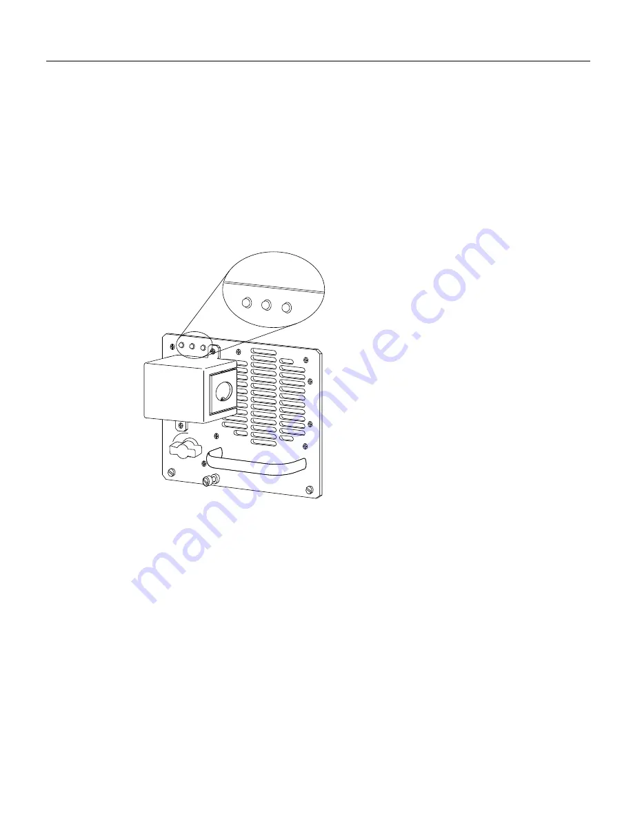
The power supply LEDs include the DC OK LED, the fan OK LED, and the output fail LED. (See
Figure 2.) The DC OK LED is on when the input power is applied. The fan OK LED is normally on;
however, it is off if the power supply fan fails. The output fail LED is normally off, but flashes at
power on for a lamp test.
Figure 2
Power Supply LEDs
The output fail LED lights for either of the following reasons:
•
Power supply DC-output failure, which could be caused by overload by the system or an actual
failure in the DC-input power.
•
Power shutdown, initiated by the power supply because it detected an out-of-tolerance voltage
condition in the power supply
In systems with a single power supply, and in systems with redundant power when both power
supplies are shutting down, the output fail LED lights momentarily as the system ramps down, but
goes out when the power supply has completely shut down.
The power supplies feature the following three safety interlock features:
•
An on/off switch with a locking mechanism (see Figure 3) on each power supply prevents the
power supply from being removed from the chassis when the power supply switch is in the ON
(|) position. When the switch is ON, a metal tab extends into a slot in the chassis. When the switch
is OFF (O), the tab is raised and clears the slot.
H4285
0
I
OK
OK
FAIL
DC
FAN OUTPUT
OK
OK
FAIL
DC
FAN OUTPUT
For the DC-input
power supply


