1200-Watt DC-Input Power Supply Replacement Instructions 11
Removing and Replacing a Power Supply
Caution
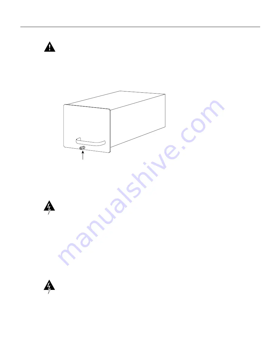
To maintain agency compliance requirements and meet EMI emissions standards in
Cisco 7513 chassis with a single power supply, the power supply blank must remain in the power
supply bay adjacent to the power supply. (See Figure 7.) Do not remove this blank from the chassis
unless you do so to install a redundant power supply. To prevent system problems, do not mix
AC-input and DC-input power supplies in the same chassis.
Figure 7
Power Supply Blank
Replacing a Power Supply
Follow these steps to replace the power supply:
Warning
Before performing any of the following procedures, ensure that power is removed from
the DC circuit. To ensure that all power is OFF, locate the circuit breaker on the panel board that
services the DC circuit, switch the circuit breaker to the OFF position, and tape the switch handle of
the circuit breaker in the OFF position. (To see translated version of this warning, refer to page
page 20.)
Step 1
Hold the power supply as shown in Figure 6 and slide it into the power supply bay. Push
the supply all the way into the chassis until the sides are flush against the chassis frame. To
prevent damaging the backplane connector, do not jam the power supply into the bay.
Step 2
Use the slotted screwdriver to tighten the captive screw that secures the power supply to the
chassis frame. (See Figure 5.)
Warning
When stranded wiring is required, use approved wiring terminations, such as closed-loop
or spade-type with upturned lugs. These terminations should be the appropriate size for the wires
and should clamp both the insulation and conductor. (To see translated versions of this warning, refer
to page 23.)
Step 3
If not already done, route the DC-input power cable through the conduit from your power
source, through the conduit bracket on the power supply (see Figure 8), and make a
sufficient length of wire available to attach to the three terminal block connections.
H3539
Captive screw


