background image

S e n d   d o c u m e n t a t i o n   c o m m e n t s   t o   m d s f e e d b a c k - d o c @ c i s c o . c o m

2-17

Cisco MDS 9100 Series Hardware Installation Guide

OL-21514-01

Chapter 2      Installing the Cisco MDS 9100 Series

    Installing the Switch in a Cabinet with Insufficient Front Clearance

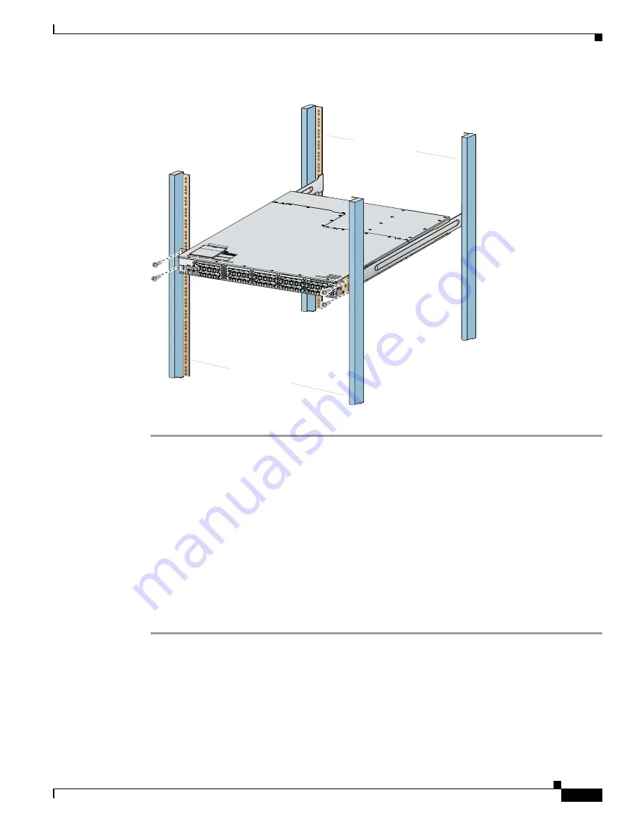
Figure 2-12

Attaching the Cisco MDS 9100 Series Switch (Rear-Facing) to the Cabinet

b.

Repeat for the front rack-mount bracket on the other side of the switch.

If you are installing the optional cable guides, place the cable guides in front of the front rack-mount 
brackets, and then pass the screws through the cable guides, front rack-mount brackets, and rear 
mounting rail. You can install one or both cable guides; if installing a single cable guide, it can be 
installed on either side.

Installing a Cisco MDS 9148 Switch, Cisco MDS 9134 Switch, or a 
Cisco MDS 9124 Switch Rear-Facing into Cabinet

To install a Cisco MDS 9134 Switch, Cisco MDS 9134 Switch, or a Cisco MDS 9124 Switch rear-facing 
into a cabinet using the rack-mount kit provided with the switch (for cabinets with insufficient 
front-facing clearance), follow these steps:

Step 1

Install the notched slider rails in the rack:

Rear cabinet

mounting

rails

Front cabinet

mounting

rails

11

3

4

3

0

Содержание MDS 9120 - Fabric Switch

Страница 1: ... d o c c i s c o c o m Americas Headquarters Cisco Systems Inc 170 West Tasman Drive San Jose CA 95134 1706 USA http www cisco com Tel 408 526 4000 800 553 NETS 6387 Fax 408 527 0883 Cisco MDS 9100 Series Hardware Installation Guide February 2010 Text Part Number OL 21514 01 ...

Страница 2: ... to use the equipment may be limited by FCC regulations and you may be required to correct any interference to radio or television communications at your own expense You can determine whether your equipment is causing interference by turning it off If the interference stops it was probably caused by the Cisco equipment or one of its peripheral devices If the equipment causes interference to radio ...

Страница 3: ...rade 13 Cisco NX OS 13 Cisco Fabric Manager 13 Command Line Interface 14 Intelligent Storage Networking Services Configuration Guides 14 Troubleshooting and Reference 14 Product Overview 1 1 Cisco MDS 9100 Series Multilayer Fabric Switches 1 2 Cisco MDS 9148 Switch 1 3 Cisco MDS 9134 Switch 1 3 Cisco MDS 9124 Switch 1 5 Cisco MDS 9140 Switch 1 5 Cisco MDS 9120 Switch 1 6 Cisco MDS Fibre Channel Bl...

Страница 4: ...sufficient Front Clearance 2 11 Installing Front Rack Mount Brackets for Cabinets with 26 Inches or Greater of Rail Spacings 2 13 Installing Front Rack Mount Brackets for Cabinets with Less Than 26 Inches of Rail Spacings 2 14 Installing Cisco MDS 9100 Series Switch Rear Facing into Cabinet 2 15 Installing a Cisco MDS 9148 Switch Cisco MDS 9134 Switch or a Cisco MDS 9124 Switch Rear Facing into Ca...

Страница 5: ...Fiber Optic Cables 3 9 Cabinet and Rack Installation A 1 Cabinet and Rack Requirements A 1 General Requirements for Cabinets and Racks A 1 Requirements Specific to Perforated Cabinets A 2 Reference Perforated Cabinet A 2 Requirements Specific to Solid Walled Cabinets A 3 Requirements Specific to Standard Open Racks A 3 Requirements Specific to Telco Racks A 3 Cisco MDS 9000 Family Telco and EIA Sh...

Страница 6: ...r Cisco CWDM SFP Transceivers B 11 Cisco DWDM SFP Transceivers B 12 Performance B 14 Connectors and Cabling B 14 Environmental and Electrical Specifications for Cisco DWDM SFP Transceivers B 15 Optical Specifications for Cisco DWDM SFP Transceivers B 15 X2 Transceiver Specifications B 17 Cisco 10 Gbps Ethernet X2 Transceivers B 18 General Specification for Cisco 10 Gbps Ethernet X2 Transceivers B ...

Страница 7: ... d o c u m e n t a t i o n c o m m e n t s t o m d s f e e d b a ck d o c c i s c o c o m Contents 5 Cisco MDS 9100 Series Hardware Installation Guide OL 21514 01 Chassis and Network Information D 4 I N D E X ...

Страница 8: ...Se n d d o c u m e n t a t i o n c o m m e n t s t o m d s f e e d b a ck d o c c i s c o c o m Contents 6 Cisco MDS 9100 Series Hardware Installation Guide OL 21514 01 ...

Страница 9: ... Multilayer Fabric Switch support The 48 port Cisco MDS 9148 Multilayer Fabric Switch 5 0 1a Product Overview chapter and Technical Specifications appendix Cisco MDS Fibre Channel Blade Switch Description of the Cisco MDS 8 Gb Fabric Switch for HP BladeSystem C Class 5 0 1a Product Overview chapter Cisco 10 Gbps Ethernet X2 Transceivers Added Cisco 10 Gbps Ethernet X2 Transceivers support 4 2 1 Te...

Страница 10: ... Not release specific Installing the Cisco MDS 9100 Series chapter Troubleshooting Troubleshooting chapter removed Not release specific For troubleshooting information see the Cisco MDS 9000 Family Troubleshooting Guide Cisco MDS 9124 Switch The 24 port Cisco MDS 9124 Switch 3 1 1 This guide Rear facing chassis installation Chassis installation for a cabinet with insufficient front side clearance ...

Страница 11: ...follows Chapter Title Description Chapter 1 Product Overview Provides an overview of the Cisco MDS 9100 Series Fixed Configuration Fabric Switch and its components Chapter 2 Installing the Cisco MDS 9100 Series Describes how to install the Cisco MDS 9100 Series and includes how to install power supplies and fan modules Chapter 3 Connecting the Cisco MDS 9100 Series Describes how to connect the Cis...

Страница 12: ...for preventing accidents Use the statement number provided at the end of each warning to locate its translation in the translated safety warnings that accompanied this device Statement 1071 Waarschuwing Dit waarschuwingssymbool betekent gevaar U verkeert in een situatie die lichamelijk letsel kan veroorzaken Voordat u aan enige apparatuur gaat werken dient u zich bewust te zijn van de bij elektris...

Страница 13: ...incidenti La traduzione delle avvertenze riportate in questa pubblicazione si trova nel documento Regulatory Compliance and Safety Information Conformità alle norme e informazioni sulla sicurezza che accompagna questo dispositivo Advarsel Dette varselsymbolet betyr fare Du befinner deg i en situasjon som kan føre til personskade Før du utfører arbeid på utstyr må du vare oppmerksom på de faremomen...

Страница 14: ...DS 9000 Family Compatibility Information Cisco Data Center Interoperability Support Matrix Cisco MDS 9000 NX OS Hardware and Software Compatibility Information and Feature Lists Cisco MDS NX OS Release Compatibility Matrix for Storage Service Interface Images Cisco MDS 9000 Family Switch to Switch Interoperability Configuration Guide Cisco MDS NX OS Release Compatibility Matrix for IBM SAN Volume ...

Страница 15: ...abric Configuration Guide Cisco MDS 9000 Family NX OS Quality of Service Configuration Guide Cisco MDS 9000 Family NX OS Security Configuration Guide Cisco MDS 9000 Family NX OS IP Services Configuration Guide Cisco MDS 9000 Family NX OS Intelligent Storage Services Configuration Guide Cisco MDS 9000 Family NX OS High Availability and Redundancy Configuration Guide Cisco MDS 9000 Family NX OS Inte...

Страница 16: ... 9000 Family SANTap Deployment Guide Cisco MDS 9000 Family Data Mobility Manager Configuration Guide Cisco MDS 9000 Family Storage Media Encryption Configuration Guide Cisco MDS 9000 Family Secure Erase Configuration Guide Cisco MDS 9000 Family Cookbook for Cisco MDS SAN OS Troubleshooting and Reference Cisco NX OS System Messages Reference Cisco MDS 9000 Family NX OS Troubleshooting Guide Cisco M...

Страница 17: ...e Channel port switch The Cisco MDS 9140 is a 40 port Fibre Channel switch The Cisco MDS 9120 is a 20 port Fibre Channel switch Note The Cisco MDS 9120 and the Cisco MDS 9140 Fibre Channel switches are not supported on NX OS Release 4 1 1b The Cisco MDS 9100 Series is packaged in compact 1 RU enclosures with redundant hot swappable power supplies The Cisco MDS 9140 Switch the Cisco MDS 9120 Switch...

Страница 18: ... with an additional license The 10 Gbps ports are also available through an additional license On Demand Port activation licensing provides 16 32 or 48 licensed ports by default in the Cisco MDS 9148 Switch Port capacity of 16 and 32 port models can be increased on site to 48 ports with an additional license in 8 port increments Expansion of Cisco MDS 9134 Switches up to 64 ports or more is possib...

Страница 19: ... 32 or 48 ports The 16 and 32 models can be upgraded up to 48 ports with the 8 port upgrade license See Figure 1 1 The Cisco MDS 9148 Switch supports N port identifier virtualization NPIV NPIV can assign multiple FC IDs to a single N port This feature allows multiple applications on the N port to use different identifiers and allows access control zoning and port security at the application level ...

Страница 20: ...S 9134 Switch can be configured as ISLs for larger MDS switches on which the DS X9704 module is installed The 10 Gbps interfaces support the copper CX4 X2 transceivers and optical media For more information see the Installing Cisco MDS 9134 48 Port and 64 Port Bundles section on page 2 21 Cisco MDS 9134 Multilayer Fabric Switch supports N port identifier virtualization NPIV NPIV can assign multipl...

Страница 21: ...ensed Two additional licenses are required to license all 24 ports See Figure 1 3 Figure 1 3 Cisco MDS 9124 Switch Cisco MDS 9124 Multilayer Fabric Switch supports N port identifier virtualization NPIV NPIV can assign multiple FC IDs to a single N port This feature allows multiple applications on the N port to use different identifiers and allows access control zoning and port security at the appl...

Страница 22: ...outstanding performance between blade switches and the rest of the Fibre Channel infrastructure The Cisco MDS Fibre Channel Blade Switch for IBM BladeCenter provides 4 Gbps Fibre Channel performance to blade server switching It also provides network intelligence features such as virtual SANs VSANs quality of service QoS and N port identifier virtualization NPIV It also offers nondisruptive softwar...

Страница 23: ...tch has 8 1 2 4 and 8 Gbps SFP ports at the front panel and has 16 2 4 and 8 Gbps serdes connections to the backplane The 16 ports are internal for server connections and 8 ports are external or SAN facing The Cisco MDS 8 Gb Fabric Switch ports are grouped Each port group consists of 4 ports The Cisco MDS 8 Gb Fabric Switch external ports include hot swappable Small Form Factor Pluggable SFP line ...

Страница 24: ...ncludes a reset button on the left side of the switch as shown in Figure 1 6 Figure 1 6 Reset Button on the Side of the Cisco MDS 9134 Switch Fan Modules The Cisco MDS 9148 Switch Cisco MDS 9140 Switch the Cisco MDS 9134 Switch and the Cisco MDS 9120 Switch support two hot swappable fan modules that allow the switches to continue to run if a fan module fails or is removed or both The switches woul...

Страница 25: ...us is also indicated on a front panel LED Procedures for replacing and installing the fan modules are available in the Removing and Installing Components section on page 2 25 Cisco MDS 9100 Series Ports The Cisco MDS 9100 Series provides host target and Inter Switch Link ISL connectivity Ports on the Cisco MDS 9148 Switch The Cisco MDS 9148 Switch provides up to 48 autosensing and autonegotiating ...

Страница 26: ...ign the port license to another unused available port for recovery resiliency You can re assign the licensed ports to any of the 48 physical ports up to the permitted number of licensed ports Table 1 1 Port Group Mapping on the Cisco MDS 9148 Switch Ports Port Group Front panel fc1 33 36 Port group 0 Front panel fc1 29 32 Port group 1 Front panel fc1 25 28 Port group 2 Front panel fc1 45 48 Port g...

Страница 27: ...ink ISL The Cisco MDS 9134 Switch includes hot swappable SFP interfaces All SFP interfaces are 1 2 and 4 Gbps with autosensing capabilities Individual ports can be configured with either short or long wavelength SFP optics for connectivity up to 860 meters and 10 kilometers respectively The two 10 Gbps ports support X2 form factor optics either copper or optical Figure 1 8 shows the Cisco MDS 9134...

Страница 28: ...co MDS 9124 Ports Ports on the Cisco MDS 9140 Switch and the Cisco MDS 9120 Switch On the Cisco MDS 9140 Switch and the Cisco MDS 9120 Switch bandwidth optimized ports are on the left side of the front panel surrounded by a white border These ports are best used for applications requiring very high bandwidth for example ISL connections between switches and high performance host or target controlle...

Страница 29: ... Cisco MDS 9120 Switch Ports Switch LEDs The front panel of the Cisco MDS 9100 Series includes the LEDs shown in Figure 1 11 Figure 1 12 Figure 1 13 and Figure 1 14 You can use the LEDs on this panel to quickly identify system status Figure 1 11 Cisco MDS 9148 Switch LEDs 1 Console port 3 Bandwidth optimized switching ports 2 10 100 Ethernet management port 4 Host optimized switching port groups 9...

Страница 30: ... 1 Product Overview Switch LEDs Figure 1 12 Cisco MDS 9134 Switch LEDs Figure 1 13 Cisco MDS 9124 Switch LEDs 184093 3 4 5 2 1 1 Switch status LED 4 10 100 Ethernet management port link LED 2 Power supply LED 5 10 100 Ethernet management port activity LED 3 Fan module status LED 1 Switch status LED 3 Fan module status LED 2 Power supply LED 4 Reset button 159834 3 4 1 2 ...

Страница 31: ...ormal initialization sequence Orange The module is booting or running diagnostics normal initialization sequence Switch temperature is high A minor threshold was exceeded during environmental monitoring Red The diagnostic test failed The module is not operational because a fault occurred during the initialization sequence Switch overheated A major threshold was exceeded during environmental monito...

Страница 32: ...vers with LWL transceivers and the cable must not exceed the stipulated cable length for reliable communications SFP tranceivers can also be used in extended distances but it would depend on the allocation of available Buffer To Buffer B2B credits on specific ports in the switch For more information on Buffer to Buffer B2B credits see the Configuring Interface Buffers chapter in the Cisco MDS 9000...

Страница 33: ...ulti mode fiber Transmission ranges for 4 Gbps are as follows Long wavelength Up to 6 2 miles 10 km on 9 micron single mode fiber Short wavelength Up to 546 yards 500 m on 50 micron multi mode fiber Short wavelength Up to 328 yards 300 m on 62 5 micron multi mode fiber Transmission ranges for 8 Gbps are as follows Long wavelength Up to 6 2 miles 10 km on 9 micron single mode fiber Short wavelength...

Страница 34: ...cal add drop multiplexers OADMs CWDM SFP transceivers can be used in two ways CWDM transmission can send and receive up to eight laser wavelengths carrying different signals simultaneously on the same optical fiber using an OADM ELWL signals can transmit over longer distances than LWL SFP transceivers There are eight different colors of CWDM SFP transceivers one for each fixed wavelength The fiber...

Страница 35: ...ollowing information Preinstallation page 2 2 Installing the Switch in a Cabinet or Rack page 2 5 Installing the Switch in a Cabinet with Insufficient Front Clearance page 2 11 Installing Cisco MDS 9134 48 Port and 64 Port Bundles page 2 21 Grounding the Switch page 2 23 Starting Up the Switch page 2 24 Removing and Installing Components page 2 25 Note Before you install operate or service the sys...

Страница 36: ...special tool lock and key or other means of security Statement 1017 Warning Only trained and qualified personnel should be allowed to install replace or service this equipment Statement 1030 Note Each new switch requires a license see the Cisco MDS 9000 Family NX OS Licensing Guide for instructions on installing a license Preinstallation This section includes the following information Installation...

Страница 37: ...rflow requirements are listed in Appendix B Technical Specifications Ensure the air conditioning meets the heat dissipation requirements listed in Appendix B Technical Specifications Ensure the cabinet or rack meets the requirements listed in Appendix A Cabinet and Rack Installation Note If the front cabinet mounting rails are not offset from the front door or bezel panel by a minimum of 3 in 7 6 ...

Страница 38: ...crews 4 in lb M3 screws 4 in lb M4 screws 12 in lb 10 32 screws 20 in lb 12 24 screws 30 in lb Required Equipment Gather the following tools before beginning the installation Number 1 Phillips screwdriver with torque capability 3 16 in flat blade screwdriver Tape measure and level ESD wrist strap or other grounding device Antistatic mat or antistatic foam The following additional items not found i...

Страница 39: ...ment follow these steps Step 1 Compare the shipment to the equipment list provided by your customer service representative and verify that you have received all items including the following Print documentation and CD ROMs Grounding lug kit Rack mount kit ESD wrist strap Cables and connectors Any optional items ordered Step 2 Check for damage and report any discrepancies or damage to your customer...

Страница 40: ...er front rack mount bracket on the other side of the switch Step 2 Install the C brackets as follows Note Two C brackets are shipped preinstalled on the switch using three M3 screws per bracket This installation step is only necessary if the C brackets were removed a Position one of the C brackets against the side of the switch and align the screw holes as shown in Figure 2 1 Then attach the brack...

Страница 41: ...g the notched slider rails for the Cisco MDS 9134 or the Cisco MDS 9124 Switch see Figure 2 3 Note Depending on when you purchased your Cisco MDS 9124 Switch you may have straight slider rails like those shown in Figure 2 2 or you may have the notched slider rails like those shown in Figure 2 3 Refer to the illustrations that show the type of rails that came with your switch Step 4 Attach the slid...

Страница 42: ...Hardware Installation Guide OL 21514 01 Chapter 2 Installing the Cisco MDS 9100 Series Installing the Switch in a Cabinet or Rack b Use the tape measure and level to verify that the rails are horizontal and at the same height Figure 2 2 Installing the Slider Rails Figure 2 3 Installing the Notched Slider Rails 91631 182459 ...

Страница 43: ...itch between the front rack mounting rails as shown in Figure 2 4 If you are using the notched rails for the Cisco MDS 9148 Switch Cisco MDS 9134 Switch or the Cisco MDS 9124 Switch see Figure 2 5 b Align the two C brackets on either side of the switch with the slider rails installed in the rack Slide the C brackets onto the slider rails and then gently slide the switch all the way into the rack I...

Страница 44: ...s to the front rack mounting rails a Insert two screws 12 24 or 10 32 depending on rack type and through the cage nuts and the holes in one of the front rack mount brackets and into the threaded holes in the rack mounting rail see Figure 2 6 or Figure 2 7 b Repeat for the front rack mount bracket on the other side of the switch If you are installing the optional cable guides place the cable guides...

Страница 45: ...e Rack Figure 2 7 Attaching the Cisco MDS 9148 Cisco MDS 9134 Switch or the Cisco MDS 9124 Switch to the Rack Notched Rails Installing the Switch in a Cabinet with Insufficient Front Clearance This section describes how to use the rack mount kit provided with the switch to install the Cisco MDS 9100 Series switch into a cabinet with insufficient front facing clearance The Cisco MDS 9100 Series swi...

Страница 46: ...ance between the inside of the front door or bezel panel and the front cabinet mounting rails This rear facing installation is necessary to ensure that the minimum bend radius for the fiber optic cables is maintained In these cabinets the Cisco MDS 9100 Series switch is mounted backwards with the fiber optic cables facing toward the rear of the cabinet and the power supplies facing the front of th...

Страница 47: ...the front rack mount brackets against the side of the switch and align the screw holes as shown in Figure 2 8 Then attach the bracket to the switch with the three M4 screws originally provided with the bracket b Repeat with the other front rack mount bracket on the other side of the switch Step 2 Install the C brackets as follows Note Two C brackets are shipped preinstalled on the switch using thr...

Страница 48: ...he side of the switch and align the screw holes as shown in Figure 2 9 Then attach the bracket to the switch with two of the three M4 screws originally provided with the bracket b Repeat with the other front rack mount bracket on the other side of the switch Note The front rack mount bracket does not align with all three holes in the Cisco MDS 9100 Series switch in this configuration The two screw...

Страница 49: ...24 Switch rear facing into a cabinet using the rack mount kit provided see Installing a Cisco MDS 9148 Switch Cisco MDS 9134 Switch or a Cisco MDS 9124 Switch Rear Facing into Cabinet section on page 2 17 Step 1 Install the slider rails in the rack a Position one of the slider rails against the front rack mounting rails and align the screw holes as shown in Figure 2 10 Then attach them using two 1...

Страница 50: ...der Rails b Align the two C brackets on either side of the switch with the slider rails installed in the rack Slide the C brackets onto the slider rails and then gently slide the switch all the way into the rack If the switch does not slide easily try realigning the C brackets on the slider rails Step 3 Stabilize the switch in the rack by attaching the front rack mount brackets to the rear rack mo...

Страница 51: ...n front of the front rack mount brackets and then pass the screws through the cable guides front rack mount brackets and rear mounting rail You can install one or both cable guides if installing a single cable guide it can be installed on either side Installing a Cisco MDS 9148 Switch Cisco MDS 9134 Switch or a Cisco MDS 9124 Switch Rear Facing into Cabinet To install a Cisco MDS 9134 Switch Cisco...

Страница 52: ...e slider rails and then let the cord dangle while you proceed with the next steps Figure 2 15 shows a power cord correctly routed through the open cutout in the slider rail b Position one of the slider rails against the front rack mounting rails and align the screw holes as shown in Figure 2 13 Then attach them using two 12 24 screws or two 10 32 screws depending on the rack rail thread type For r...

Страница 53: ...he slider rails installed in the rack Slide the C brackets onto the slider rails and then gently slide the switch all the way into the rack If the switch does not slide easily try realigning the C brackets on the slider rails Step 3 Connect the power cord that you previously routed through the open cutout of the slider rail to the switch as shown in Figure 2 15 Limit the length of the power cord b...

Страница 54: ...rdware Installation Guide OL 21514 01 Chapter 2 Installing the Cisco MDS 9100 Series Installing the Switch in a Cabinet with Insufficient Front Clearance Figure 2 15 Correct Position of Power Cord Routed Through Notched Slider Rail Figure 2 16 Incorrect Position of Power Cord Routed Over the Notched Slider Rail 182466 182467 ...

Страница 55: ...ng to the Cabinet b Repeat for the front rack mount bracket on the other side of the switch Tip If the chassis exceeds the 1 RU space on the low side of the rack you may have difficulty installing other equipment In this situation loosen the screws on the front and back rails of the chassis and raise it to the top of the RU space by pushing the chassis up until it cannot go any further Then retigh...

Страница 56: ... 10 Gbps ports of the switches can be a maximum of 1 meter Currently only 1 meter cables are shipped with the boxes Step 3 Ensure that a copper X2 CX4 transceiver is plugged into the 10 Gbps port of each switch Step 4 Plug in one end of the copper cable in the same box that is supplied to the 10 Gbps transceiver of the MDS 9134 Switch Plug in the other end to the 10 Gbps transceiver of the MDS 913...

Страница 57: ...cted last Statement 1046 Caution We recommend grounding the chassis even if the rack is already grounded Note If the rack is less than 25 in 635 mm deep the slider rails will cover the grounding hole Therefore the rack must either be grounded or at least 25 in 635 mm deep Caution All power supplies must be grounded The receptacles of the AC power cables used to provide power to the chassis must be...

Страница 58: ...nd Starting Up the Switch This section provides instructions for powering up the switch and verifying component installation Caution During this procedure wear grounding wrist straps to avoid ESD damage to the switch Note Do not connect the MGMT 10 100 Ethernet port to the LAN until the initial switch configuration has been performed For instructions on connecting to this port see the Connecting t...

Страница 59: ...processes are complete see the Cisco MDS 9000 Family Troubleshooting Guide Step 8 Try removing and reinstalling a component that is not operating properly If it still does not operate correctly contact your customer service representative for a replacement Note If you purchased Cisco support through a Cisco reseller contact the reseller directly If you purchased support directly from Cisco contact...

Страница 60: ...present on the backplane when the system is operating Use caution when servicing Statement 1034 Caution During this procedure wear grounding wrist straps to avoid ESD damage to the switch Note Except for the Cisco MDS 9124 switch all the the other Cisco MDS 9100 Series switches are supported for operation with both power supplies and both fan modules installed and with all fans working With two po...

Страница 61: ...d o c c i s c o c o m 2 27 Cisco MDS 9100 Series Hardware Installation Guide OL 21514 01 Chapter 2 Installing the Cisco MDS 9100 Series Removing and Installing Components Figure 2 21 Rear View of the Cisco MDS 9134 Switch Power module Fan module Power module Fan module 184097 ...

Страница 62: ... Switch and the Cisco MDS 9120 Switch the fans should not be removed for prolonged periods of time during operation If one fan module fails a single healthy fan module can temporarily provide sufficient cooling to maintain switch operation under normal conditions but the failed fan module should be replaced as soon as possible See Figure 2 23 Figure 2 23 Rear View of the Cisco MDS 9140 Switch and ...

Страница 63: ...wer supply designated for your Cisco 9100 Series switch Using an incorrect power supply will not provide redundant power in the case of a power supply failure Removing Power Supplies To remove a AC power supply follow these steps Step 1 Turn the power switch to the off 0 position on the power supply that you are removing Step 2 Disconnect the power cord from the power source Step 3 Loosen the capt...

Страница 64: ...Troubleshooting Guide Removing and Installing DC Power Supplies This section provides instructions for removing and installing the DC power supplies for the Cisco MDS 9100 Series switch Note The new DC power supply is not supported on the Cisco MDS 9140 Switch Cisco MDS 9148 Switch and the Cisco MDS 9120 Switch The DC power supply does NOT use country specific power cords like its AC power supply ...

Страница 65: ...dant power in the case of a power supply failure Removing Power Supplies Note The new DC power supply does not have a built in power switch unlike the AC power supply To remove a DC power supply follow these steps Step 1 Turn the power switch breaker or other power disconnect device to off 0 position on the actual DC power source Step 2 Disconnect the wires from the DC power supply terminal blocks...

Страница 66: ... Family Troubleshooting Guide Removing and Installing Fan Modules This section provides instructions for removing and installing the fan modules for the Cisco MDS 9148 Switch Cisco MDS 9140 Switch and the Cisco MDS 9120 Switch The Cisco MDS 9124 Switch does not have field replaceable fan modules Removing a Fan Module on the Cisco MDS 9148 Cisco MDS 9140 Switch the Cisco MDS 9134 Switch and the Cis...

Страница 67: ...Guide OL 21514 01 Chapter 2 Installing the Cisco MDS 9100 Series Removing and Installing Components Step 1 Locate the fan module in the back of the switch Step 2 Slide the seating tabs toward the center of the fan module Step 3 Grasp the fan module handle and pull it outward Step 4 Pull the fan module out of the switch and put it in a safe place ...

Страница 68: ...and the Cisco MDS 9134 Switch Step 2 Slide the fan module into the switch until it clicks into place Figure 2 26 Cisco MDS 9100 Series Fan Module Figure 2 27 shows the Cisco MDS 9148 and the MDS 9134 fan module Figure 2 27 Cisco MDS 9148 and MDS 9134 Fan Module Caution Although the fan modules for the Cisco MDS 9134 and Cisco MDS 9148 switches appear to be similar there is a difference between the...

Страница 69: ...etely in the switch and the faceplate is flush with the switch back panel Step 2 Verify that the fan module LED is green If the LED is orange then one fan has failed in this fan module if the LED is red then both fans have failed in this fan module Step 3 Contact your customer service representative for assistance if after several attempts the fans do not operate or you experience trouble with the...

Страница 70: ...t a t i o n c o m m e n t s t o m d s f e e d b a ck d o c c i s c o c o m 2 36 Cisco MDS 9100 Series Hardware Installation Guide OL 21514 01 Chapter 2 Installing the Cisco MDS 9100 Series Removing and Installing Components ...

Страница 71: ...of the Cisco MDS 9100 Series Fixed Configuration Fabric Switch and it includes the following information Preparing for Network Connections page 3 1 Connecting the Console Port page 3 1 Connecting the 10 100 and 10 100 1000 Ethernet Management Port page 3 4 Connecting to a Fibre Channel Port page 3 4 Preparing for Network Connections When preparing your site for network connections to the Cisco MDS...

Страница 72: ...nnecting the Console Port to a PC You can connect the console port to a PC serial port for local administrative access to the Cisco MDS 9100 Series switch Note The PC must support VT100 terminal emulation The terminal emulation software frequently a PC application such as HyperTerminal Plus makes communication between the Cisco MDS 9100 Series switch and your PC possible during setup and configura...

Страница 73: ...plied console cable a rollover RJ 45 to RJ 45 cable to the console port see Figure 3 1 Step 2 Connect the other end of the console cable to the supplied RJ 45 to DB 25 adapter Step 3 Connect the RJ 45 to DB 25 adapter to the DB 25 port on the modem Step 4 Power on the switch The switch boots automatically and the following default console port characteristics are applied to the modem connection 96...

Страница 74: ...r information about configuring the switch for in band management see the Cisco Fabric Manager Fundamentals Configuration Guide and the Cisco NX OS Fundamentals Configuration Guide The Cisco MDS 9000 Family supports both Fibre Channel and Gigabit Ethernet protocols for SFP transceivers Each transceiver must match the transceiver on the other end of the cable and the cable must not exceed the stipu...

Страница 75: ...ote Use only Cisco SFP transceivers on the Cisco MDS 9100 Series Each Cisco SFP transceiver is encoded with model information that enables the switch to verify that the SFP transceiver meets the requirements for the switch Note On the Cisco MDS 9124 Switch the tabs on the SFP transceivers in the top row are at the bottom of the port The tabs on the SFP transceivers in the bottom row are at the top...

Страница 76: ...p and follow its instructions for use Step 2 Perform these steps if cable is installed in the transceiver a Record the cable and port connections for later reference b Press the release latch on the cable grasp the connector near the connection point and gently pull the connector from the transceiver c Insert a dust plug into the connector on the cable d Insert a dust plug into the cable end of th...

Страница 77: ...sco MDS 9120 Switch Step 4 Insert a dust cover into the port end of the transceiver and place the transceiver on an antistatic mat or into a static shielding bag if you plan to return it to the factory Step 5 Protect the optical cage by inserting a clean cover if another transceiver is not being installed Removing and Installing Cables into SFP Transceivers Caution To prevent damage to the fiber o...

Страница 78: ... the cable end of the transceiver Step 4 Align the cable connector with the transceiver and insert the connector into the transceiver until it clicks into place See Figure 3 6 Figure 3 6 Connecting the LC Type Cable to a Fibre Channel Port Caution If the cable does not install easily ensure it is correctly oriented before continuing For instructions on verifying connectivity see the Cisco Fabric M...

Страница 79: ...ht is increased by contamination and it should be kept below 0 35 dB Follow these maintenance guidelines SFP transceivers are static sensitive To prevent ESD damage wear an ESD preventive wrist strap that is connected to the chassis Do not remove and insert a transceiver more often than necessary Repeated removals and insertions can shorten its useful life Keep all optical connections covered when...

Страница 80: ...t a t i o n c o m m e n t s t o m d s f e e d b a ck d o c c i s c o c o m 3 10 Cisco MDS 9100 Series Hardware Installation Guide OL 21514 01 Chapter 3 Connecting the Cisco MDS 9100 Series Connecting to a Fibre Channel Port ...

Страница 81: ...ted types listed above standard perforated or solid walled with a fan tray General Requirements for Cabinets and Racks The cabinet or rack must be one of the following rack types Standard 19 in four post EIA cabinet or rack with mounting rails that conform to English universal hole spacing per section 1 of ANSI EIA 310 D 1992 See the Requirements Specific to Perforated Cabinets section on page A 2...

Страница 82: ...y in the way of the chassis air intake or exhaust vents Note Optional jumper power cords are available for use in a cabinet See the Jumper Power Cord section on page C 6 Requirements Specific to Perforated Cabinets In addition to the requirements listed in the General Requirements for Cabinets and Racks section on page A 1 perforated cabinets must meet the following requirements The front and rear...

Страница 83: ...eral Requirements for Cabinets and Racks section on page A 1 if mounting the chassis in an open rack no side panels or doors ensure that the rack meets the following requirements Width between two front mounting rails minimum of 17 75 in 45 1 cm Minimum vertical rack space per chassis 1 rack unit RU equal to 1 75 in 4 4 cm The distance between the outside face of the front mounting rail and the ou...

Страница 84: ...bilized Caution If installing this kit in an EIA rack attach the switch to all four rack mounting rails the EIA rails may not be thick enough to prevent flexing of the shelf brackets if only two rails are used Before rack mounting the chassis ensure that the cabinet or rack meets the following requirements The specifications listed in the Cabinet and Rack Requirements section on page A 1 The depth...

Страница 85: ... following equipment for this installation Number 2 Phillips screwdriver Tape measure and level to ensure shelf brackets are level Installing the Shelf Bracket Kit into a Two Post Telco Rack Figure A 1 shows the installation of the shelf bracket kit into a two post telco rack Figure A 1 Installing the Shelf Bracket Kit into a Telco Rack Table A 1 Contents of Shelf Bracket Kit Quantity Part Descrip...

Страница 86: ...n the screw holes at the front of the shelf bracket with the holes in the rack mounting rail Then attach the shelf bracket to the rack mounting rail using a minimum of four 12 24 or 10 24 screws Note The bottom hole of the shelf bracket should align with the bottom hole of a rack unit on the rack mounting rail the hole immediately above the 1 2 in spacing Step 2 Repeat with the other shelf bracket...

Страница 87: ...steps Step 1 Position a shelf bracket inside the rack mounting rails as shown in Figure A 2 Align the screw holes at the front of the shelf bracket with the holes in the front rack mounting rail Then attach the shelf bracket to the front rack mounting rail using a minimum of four 12 24 or 10 24 screws Note The bottom hole of the shelf bracket should align with the bottom hole of a rack unit on the...

Страница 88: ...ity Statement 1017 Warning Only trained and qualified personnel should be allowed to install replace or service this equipment Statement 1030 Note Before you install operate or service the system refer to the Regulatory Compliance and Safety Information for the Cisco MDS 9000 Family for important safety information To install the switch on top of the shelf brackets follow these steps Step 1 Verify...

Страница 89: ... been installed in a four post EIA rack and both front rack mount brackets and both C brackets are securely attached to the rack mounting rails To remove the shelf bracket kit follow these steps Step 1 Remove the screws fastening the slider brackets to the rear rack mounting rails and then slide the slider brackets out of the shelf brackets Step 2 Remove the screws fastening the crossbar to the sh...

Страница 90: ... i o n c o m m e n t s t o m d s f e e d b a ck d o c c i s c o c o m A 10 Cisco MDS 9100 Series Hardware Installation Guide OL 21514 01 Appendix A Cabinet and Rack Installation Cisco MDS 9000 Family Telco and EIA Shelf Bracket ...

Страница 91: ... page B 6 Cisco DWDM SFP Transceivers page B 12 Switch Specifications Table B 1 lists the environmental specifications for the Cisco MDS 9100 Series Table B 2 lists the physical specifications for the Cisco MDS 9100 Series Table B 1 Environmental Specifications for the Cisco MDS 9100 Series Description Specification Temperature ambient operating 32 to 104 F 0 to 40 C Temperature ambient nonoperati...

Страница 92: ... Switch Dimensions Width 17 2 in 43 69 cm Height 1 75 in 4 45 cm Depth 23 1 in 58 67 cm Depth with cable guide 28 1 in 71 37 cm Rack Unit RU Chassis requires 1 RU 1 75 in or 4 45 cm Weight 22 2 lb Cisco MDS 9148 Switch and Cisco MDS 9120 Switch chassis with two fan modules and two power supplies installed 25 lb Cisco MDS 9140 Switch and Cisco MDS 9120 Switch chassis with two fan modules and two po...

Страница 93: ...20 Switch Part Number DS C24 300AC Cisco MDS 9124 Switch and Cisco MDS 9134 Switch Part Number DS C48 300AC Cisco MDS 9148 Switch Airflow Front to back except for Cisco MDS 9148 switch where it is from back to front 250 lfm1 or 42 cfm2 through the system A minimum clearance of 2 5 in 6 4 cm is required between the chassis air vents and any walls 1 lfm linear feet per minute 2 cfm cubic feet per mi...

Страница 94: ...n Table B 4 Cisco MDS 9100 Series DC Input Power Supply Specifications DC Input Power Supply Specification DC input voltage 48 VDC to 60 VDC continuous DC input current rating maximum 8 A at 48 VDC 6 67 A at 60 VDC Note DC power supply does not use country specific power cords For more information on DC power supply see Removing and Installing DC Power Supplies section in Installing the Cisco MDS ...

Страница 95: ...basic guidelines Each power supply should have its own dedicated branch circuit Cisco MDS 9140 Switch with fan modules 204 maximum 870 3 0 2 32 1 16 Cisco MDS 9120 Switch with fan modules 180 maximum 752 2 65 2 05 1 02 Table B 5 Power and Heat Dissipation for AC Input Power Supply continued Model Number Module AC Input Power watts Heat Diss BTU hr Input Current 85 VAC amps 110 VAC amps 220 VAC amp...

Страница 96: ... transceiver meets the requirements for the switch For the list of supported SFP transceivers see the release notes For details of SFP transceivers see the data sheet at the following location http www cisco com en US prod collateral ps4159 ps6409 ps4358 product_data_sheet09186a00801b c698 html This section provides the following information Cisco Fibre Channel SFP Transceivers page B 6 Cisco Giga...

Страница 97: ...SW 4 Gbps 2 Gbps 1 Gbps Fibre Channel short wavelength SFP Short wavelength DS SFP FC4G MR 4 Gbps 2 Gbps 1 Gbps Fibre Channel long wavelength SFP Long wavelength DS SFP FC4G LW 4 Gbps 2 Gbps 1 Gbps Fibre Channel long wavelength SFP Long wavelength Table B 9 Cisco Fibre Channel SFP Transceivers for the Cisco MDS 9140 Switch and the Cisco MDS 9120 Switch Part Number Description Type DS SFP FC2G SW 2...

Страница 98: ...1310 nm Fiber type MMF SMF Core size 50 microns 62 5 microns 9 125 microns Cable distance1 1 Approximate actual distance may vary depending on fiber quality and other factors 300 m 150 m 10 km Transmit power 10 to 1 5 dBm 9 5 to 3 dBm Table B 12 Maximum Environmental and Electrical Ratings for Cisco Fibre Channel SFP Transceivers Parameter Symbol Min Max Unit Storage temperature1 1 Absolute maximu...

Страница 99: ...el SFP transceivers Note The cable distances provided are for 2 Gbps Table B 13 Cisco Gigabit Ethernet Fibre Channel SFP Transceivers Part Number Description Type DS SFP FCGE SW 1 Gbps Ethernet and 1 Gbps 2 Gbps Fibre Channel short wavelength SFP Short wavelength DS SFP FCGE LW 1 Gbps Ethernet and 1 Gbps 2 Gbps Fibre Channel long wavelength SFP Long wavelength DS SFP GE T 1 Gbps Ethernet SFP Table...

Страница 100: ...eliability is not implied and damage to the device may occur over an extended period of time between absolute maximum ratings and the recommended operating conditions TC 0 85 C Relative humidity1 RH 5 95 Module supply voltage1 VCCT R 3 1 3 5 V Table B 16 Cisco CWDM SFP Transceivers Part Number Description DS CWDM xxxx Gigabit Ethernet and 1 Gbps 2 Gbps 4 Gbps Fibre Channel SFP LC interface xxxx wh...

Страница 101: ...ivers have an optical link budget of 28 decibels db Note The parameters are specified over temperature and at end of life unless otherwise noted Table B 18 General Specifications for Cisco CWDM SFP Transceivers Description Specification Connector type LC Wavelength 1470 1490 1510 1530 1550 1570 1590 1610 nm Fiber type SMF Core size 9 125 microns Cable distance1 1 Approximate actual distance may va...

Страница 102: ...models Hot swappable input output device that plugs into Gigabit Ethernet SFP ports or slots of a Cisco switch or router linking the port with the network Table B 21 Optical Specifications for Cisco CWDM SFP Transceivers Parameter Symbol Min Typical Max Units Notes Transmitter central wavelength λc x 4 x 1 x 7 nm Available center wavelengths 1470 1490 1510 1530 1550 1570 1590 1610 nm Wavelength te...

Страница 103: ...el SFP spare DWDM SFP 5494 Cisco 1554 94 NM DWDM Gigabit Ethernet and 1 2 Gbps Fibre Channel SFP spare DWDM SFP 5413 Cisco 1554 13 NM DWDM Gigabit Ethernet and 1 2 Gbps Fibre Channel SFP spare DWDM SFP 5252 Cisco 1552 52 NM DWDM Gigabit Ethernet and 1 2 Gbps Fibre Channel SFP spare DWDM SFP 5172 Cisco 1551 72 NM DWDM Gigabit Ethernet and 1 2 Gbps Fibre Channel SFP spare DWDM SFP 5092 Cisco 1550 92...

Страница 104: ... SFP 3977 Cisco 1539 77 NM DWDM Gigabit Ethernet and 1 2 Gbps Fibre Channel SFP spare DWDM SFP 3898 Cisco 1538 98 NM DWDM Gigabit Ethernet and 1 2 Gbps Fibre Channel SFP spare DWDM SFP 3819 Cisco 1538 19 NM DWDM Gigabit Ethernet and 1 2 Gbps Fibre Channel SFP spare DWDM SFP 3661 Cisco 1536 61 NM DWDM Gigabit Ethernet and 1 2 Gbps Fibre Channel SFP spare DWDM SFP 3582 Cisco 1535 82 NM DWDM Gigabit ...

Страница 105: ... db Note The parameters are specified over temperature and at end of life unless otherwise noted Table B 23 Environmental Specifications for Cisco DWDM SFP Transceivers Description Specification Temperature ambient operating 32 to 158 F 0 and 70 C Temperature ambient nonoperating and storage 40 to 185 F 40 to 85 C Table B 24 Electrical Specifications for Cisco DWDM SFP Transceivers Parameter Symbo...

Страница 106: ...verloading conditions Transmitter Optical Output Power Pout 0 4 0 dBm Averagepower coupled into single mode fiber Receiver Receiver Optical Input Wavelength 1530 1565 nm Receiver Damage Threshold 5 dBm Power Limited Performance at OSNR of 20 dB 1 GbE or 1 Gbps FC or 21 dB 2 Gbps FC at 0 1 nm RBW Optical Input Power Pin 28 0 9 0 dBm Dispersion Power Penalty 1 GbE and 1 Gbps FC 3 dB 800 3600 ps nm D...

Страница 107: ...refer to the Regulatory Compliance and Safety Information for the Cisco MDS 9000 Family Table B 26 lists the 10 Gigabit Ethernet X2 transceiver modules available through Cisco Table B 27 lists the port cabling specifications for the 10 Gigabit X2 transceiver modules Table B 28 lists the X2 transceiver optical transmit and receive specifications Table B 26 10 Gigabit X2 Transceiver Modules X2 Trans...

Страница 108: ...rement specifications for the Cisco 10 Gbps Ethernet X2 transceiver Table B 28 X2 Transceiver Optical Transmit and Receive Specifications X2 Product Number Transceiver Type Transmit Power dBm Receive Power dBm Transmit and Receive Wavelength nm DS X2 FC10G SR 10GFC SR 850 nm MMF Max 7 3 Min 1 0 Max 9 9 Min 840 to 860 DS X2 FC10G LR 10GFC LR 1310 nm SMF 0 5 Max 8 2 Min 0 5 Max 14 4 Min 1260 to 1355...

Страница 109: ... data format transmitted by the Ethernet DWDM X2 transceiver on the fiber is identical to that transmitted by the Fibre Channel X2 transceiver except that the Fibre Channel packets are clocked at the 10 Gigabit Ethernet rate The main features of the Cisco 10 Gbps Ethernet DWDM X2 Transceiver include Support for 32 nontunable ITU 100 GHz wavelengths compatible with the Cisco ONS DWDM channel plan S...

Страница 110: ...u m e n t a t i o n c o m m e n t s t o m d s f e e d b a ck d o c c i s c o c o m B 20 Cisco MDS 9100 Series Hardware Installation Guide OL 21514 01 Appendix B Technical Specifications X2 Transceiver Specifications ...

Страница 111: ...ipment In situations where long parallel cable runs exist but cannot be separated by at least 3 3 ft 1 m we recommend that you shield these potential noise sources To avoid interference the source should be shielded by housing it in a grounded metallic conduit Cables and Adapters The Cisco MDS 9100 Series accessory kit includes the following RJ 45 to RJ 45 rollover cable RJ 45 to DB 9 female DTE a...

Страница 112: ... port on the Cisco MDS 9100 Series Connecting the Console Port to a Computer Using the DB 25 Adapter You can use the RJ 45 to RJ 45 rollover cable and RJ 45 to DB 25 female DTE adapter labeled Terminal to connect the console port to a computer running terminal emulation software Table C 2 lists the pinouts for the console port the RJ 45 to RJ 45 rollover cable and the RJ 45 to DB 25 female DTE ada...

Страница 113: ...et Port Use a modular RJ 45 straight through UTP cable to connect the 10 100 management Ethernet port to external hubs and switches To connect to a router use a crossover cable See Figure C 1 Figure C 1 RJ 45 Interface Cable Connector DSR 7 2 20 DTR CTS 8 1 4 RTS Table C 2 Port Mode Signaling and Pinouts with DB 25 Adapter continued Console Port RJ 45 to RJ 45 Rollover Cable RJ 45 to DB 25 Termina...

Страница 114: ...power cords or jumper power cords are available for connection to a power distribution unit having IEC 60320 C13 outlet receptacles The jumper power cords for use in cabinets are available as an option instead of the standard power cords Power Cords The standard power cords have an IEC C15 connector on the end that plugs into the switch The optional jumper power cords have an IEC C15 connector on ...

Страница 115: ...ovided with the switch are supported Figure C 3 shows the supported plugs for the Cisco MDS 9100 Series power supplies Figure C 3 300 W Power Supply Plugs 1 Argentina IRAM 2073 plug 10 A 5 Italy 1 3G plug CEI 23 16 10 A 2 North America NEMA 5 15P plug 15 A 6 United Kingdom BS89 13 BS 1363 A 13 A replaceable fuse 3 Australia New Zealand SAA 3 plug AS NZS 3112 1993 10 A 7 South Africa EL 208 SABS 16...

Страница 116: ...Cords and Plugs Jumper Power Cord Figure C 4 shows the C14 and C15 connectors on the optional jumper power cord for the Cisco MDS 9100 Series switch The C15 connector connects into the C14 inlet on the Cisco MDS 9100 Series power supply while the C14 connector connects into the C13 receptacle of a power distribution unit for a cabinet Figure C 4 Connectors on Jumper Power Cord for Cisco MDS 9100 S...

Страница 117: ...d Network Information page D 4 Note For information about how to query the switch for configuration information see the Cisco NX OS Fundamentals Configuration Guide and the Cisco Fabric Manager Fundamentals Configuration Guide Site Preparation Checklist Planning the location and layout of your equipment rack or wiring closet is essential for successful switch operation ventilation and accessibilit...

Страница 118: ...contamination Air flow 3 Power evaluation Input power type Power receptacles1 Receptacle proximity to the equipment Dedicated circuit for power supply Dedicated separate circuits for redundant power supplies UPS2 for power failures 1 Verify that the power supply installed in the chassis has a dedicated AC source circuit 2 UPS uninterruptible power supply 4 Grounding evaluation Circuit breaker size...

Страница 119: ...endix D Site Planning and Maintenance Records Contact and Site Information Contact and Site Information Use the following worksheet to record contact and site information Table D 2 Contact and Site Information Contact person Contact phone Contact E Mail Building site name Data center location Floor location Address line 1 Address line 2 City State Zip code Country ...

Страница 120: ...he following worksheets to record chassis and network information Contract Number ______________________________________________________________ Chassis Serial Number ______________________________________________________________ Product Number ______________________________________________________________ Table D 3 Network Related Information Switch IP address Switch IP netmask Host name Domain n...

Страница 121: ...20 switch 1 6 installing rear facing in cabinet 2 15 Cisco MDS 9124 switch 1 5 installing rear facing in cabinet 2 17 Cisco MDS 9134 Switch 1 3 Cisco MDS 9134 switch installing rear facing in cabinet 2 17 Cisco MDS 9140 switch 1 5 installing rear facing in cabinet 2 15 Cisco MDS 9148 Switch 1 3 components removing and installing 2 25 connector specifications 10 100BASE T C 4 RJ 45 3 4 twisted pair...

Страница 122: ...Fibre Channel SFP transceiver specifications B 9 H humidity specifications B 1 I IBM BladeCenter 1 6 installation cabinet or rack installation 2 5 guidelines 2 3 options 2 2 pre installation 2 2 rear facing 2 15 ISL 1 11 L LC type cables connecting to Fibre Channel ports 3 8 figure 3 8 LEDs descriptions 1 15 N network connections preparing 3 1 notched slider rails Cisco MDS 9124 switch 2 7 P physi...

Страница 123: ...e Channel 1 17 Fibre Channel Gigabit Ethernet combination 1 17 maintaining 3 9 removing and installing cables into 3 7 specifications B 6 supported 1 16 specifications CWDM SFP transceivers B 10 B 12 Gigabit Ethernet Fibre Channel SFP transceivers B 9 power B 3 SFP transceivers B 6 switch B 1 X2 transceivers B 17 starting up initial start up 2 24 switch LEDs 1 13 system ground location 2 23 T tech...

Страница 124: ...Se n d d o c u m e n t a t i o n c o m m e n t s t o m d s f e e d b a ck d o c c i s c o c o m Index IN 4 Cisco MDS 9100 Series Hardware Installation Guide OL 21514 01 ...

Отзывы: