background image

Configuring Device Security

Defining Traffic Control

ESW 500 Series Switches Administration Guide

134

5

Modifying Port Security

STEP 1

Click Security > Traffic Control > Port Security. The 

Port Security Page

 opens:

STEP 2

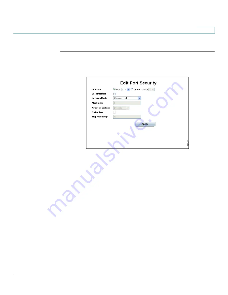
Click the Edit Button. The 

Edit Port Security Page

 opens:

Edit Port Security Page

The 

Edit Port Security Page

 contains the following fields:

Interface — Select the port or EtherChannel name.

Lock Interface — Indicates the port security status. The possible field values 
are:

-

Unchecked

 — Indicates the port is currently unlocked. This is the default 

value. 

-

Checked

 — Indicates the port is currently locked.

Learning Mode — Defines the locked port type. The Learning Mode field is 
enabled only if Locked is selected in the Interface Status field. In order to 
change the Learning Mode, the Lock Interface must be set to Unlocked. Once 
the mode is changed, the Lock Interface can be reinstated. The possible field 
values are: 

-

Classic Lock

 — Locks the port using the classic lock mechanism. The 

port is immediately locked, regardless of the number of addresses that 
have already been learned.

-

Limited Dynamic Lock

 — Locks the port by deleting the current dynamic 

MAC addresses associated with the port. The port learns up to the 

Содержание ESW-540-24 - Small Business Pro Switch

Страница 1: ...Cisco Small Business Pro ESW 500 Series Switches ADMINISTRATION GUIDE ...

Страница 2: ... id i Z jbVc CZildg VgZ igVYZbVg h0 8 Vc c i Z LVn LZ Ldg A kZ EaVn VcY AZVgc VcY 8 hXd HidgZ VgZ hZgk XZ bVg h0 VcY 6XXZhh GZ higVg 6 gdcZi 6hncXDH 7g c c i Z BZZi c Id Ndj 8ViVanhi 8896 889E 88 88 E 88C6 88CE 88HE 88KE 8 hXd i Z 8 hXd 8Zgi ZY ciZgcZildg meZgi ad d 8 hXd DH 8 hXd EgZhh 8 hXd HnhiZbh 8 hXd HnhiZbh 8Ve iVa i Z 8 hXd HnhiZbh ad d 8 hXd Jc in 8daaVWdgVi dc L i dji A b iVi dc i Zg Vhi...

Страница 3: ... Buttons 18 Performing Common Configuration Tasks 19 Checking the Software Version 19 Checking the System Information 19 Viewing what Devices are Attached to the Switch 20 Configuring the VLAN Settings for the Switch 21 Configuring individual ports using Cisco Smartport Roles 22 Smartport Roles 23 Checking the Device Power Consumption 27 Saving the Configuration 29 Upgrading the Firmware on the Sw...

Страница 4: ...Access Points 69 Configuring Smart Ports for Switches 71 Configuring Smart Ports for Routers 73 Configuring Smart ports for Guests 76 Configuring Smart ports for Servers 78 Configuring Smart ports for Printers 80 Configuring Smart ports for VS Camera 83 Configuring Smart Ports for Other 85 Chapter 4 Configuring System Time 88 Defining System Time 88 Defining SNTP Settings 92 Defining SNTP Authenti...

Страница 5: ...g Storm Control 129 Defining Port Security 130 Modifying Port Security 134 Defining 802 1x 135 Defining 802 1X Properties 136 Defining Port Authentication 138 Modifying 8021X Security 141 Defining Authentication 144 Modifying Authentication Settings 146 Authenticated Hosts 147 Defining Access Control 149 Defining MAC Based ACL 149 Adding Rule to MAC Based ACL 153 Modifying MAC Based ACL 155 Defini...

Страница 6: ... Settings 186 Querying the IP Source Binding Database 188 TCAM Resources 189 Query By 190 Query Results 190 Defining Dynamic ARP Inspection 191 Defining ARP Inspection Properties 192 Defining ARP Inspection Trusted Interfaces 194 Defining ARP Inspection List 196 Static ARP Inspection Table 197 Adding a Binding List entry 198 Assigning ARP Inspection VLAN Settings 199 Enabled VLAN Table 200 Chapter...

Страница 7: ...figuring IP Information 230 IP Addressing 230 Defining DHCP Relay 232 Defining DHCP Relay Interfaces 234 Managing ARP 236 ARP Table 238 Modifying ARP Settings 239 Domain Name System 240 Defining DNS Servers 240 Default Parameters 241 DNS Server Details 242 Mapping DNS Hosts 242 Chapter 9 Defining Address Tables 245 Defining Static Addresses 245 Defining Dynamic Addresses 248 Query By Section 250 C...

Страница 8: ...RTSP 276 Defining Multiple Spanning Tree 278 Defining MSTP Properties 279 Defining MSTP Instance to VLAN 280 Defining MSTP Instance Settings 282 Defining MSTP Interface Settings 283 Chapter 12 Configuring Quality of Service 290 Managing QoS Statistics 291 Policer Statistics 291 Add Aggregated Policer Statistics 293 Resetting Aggregate Policer Statistics Counters 296 Queues Statistics 296 Adding Qu...

Страница 9: ... Policy Profile 324 Defining Policy Binding 326 Modifying QoS Policy Binding Settings 328 Defining QoS Basic Mode 329 Rewriting DSCP Values 330 Chapter 13 Configuring SNMP 332 SNMP Versions 332 SNMP v1 and v2 332 SNMP v3 332 Configuring SNMP Security 333 Defining the SNMP Engine ID 333 Defining SNMP Views 335 Defining SNMP Users 337 Modifying SNMP Users 339 Define SNMP Groups 340 Modifying SNMP Gr...

Страница 10: ...aging Power over Ethernet Devices 371 Defining PoE Settings 371 Chapter 16 Managing System Logs 375 Enabling System Logs 375 Viewing the Device Memory Logs 377 Clearing Message Logs 378 Viewing the System Flash Logs 379 Clearing Flash Logs 380 Remote Log Servers 380 Modifying Syslog Server Settings 383 Chapter 17 Viewing Statistics 386 Viewing Ethernet Statistics 386 Defining Interface Statistics ...

Страница 11: ...ry Table 400 Defining RMON Events Control 402 Modifying RMON Event Log Settings 404 Viewing the RMON Events Logs 405 Defining RMON Alarms 406 Modifying RMON Alarm Settings 410 Chapter 18 Aggregating Ports 413 Defining EtherChannel Management 414 Defining EtherChannel Settings 416 Modifying EtherChannel Settings 418 Configuring LACP 420 Chapter 19 Managing Device Diagnostics 423 Ethernet Port Testi...

Страница 12: ...witches in Fast Ethernet and GigE models The switch models covered in this guide are This section provides information about the different methods to connect to the switch as well as some examples of a typical installation It also provides an introduction to the user interface and includes the following Typical Installation Methods page 2 Connecting to the Switch page 6 Using the Default Static IP...

Страница 13: ... and configure basic connectivity to ensure it communicates with the rest of the network The following diagram illustrates three common installation scenarios In the first two scenarios called VOICE and SECURITY DATA you are adding an ESW 500 switch to a new or existing Cisco Smart Business Communications Systems SBCS network deployment This deployment is either a VOICE network with UC520 being th...

Страница 14: ...ess is obtained via DHCP by default If the switch times out on a Dynamic Host Configuration Protocol DHCP response it falls back to a static IP address 192 168 10 2 with subnet mask of 255 255 255 0 Voice VLAN is VLAN 100 Cisco Discovery Protocol CDP is enabled on all ports Physical Connectivity Physical connections to the switch are described in the tables and graphics on the next two pages NOTE ...

Страница 15: ...ich use RJ 45 connectors The Ethernet ports support network speeds of 10 Mbps 100 Mbps or 1000 Mbps They can operate in half and full duplex modes Auto sensing technology enables each port to automatically detect the speed of the device connected to it and adjust its speed and duplex accordingly These ports are typically used for devices such as PCs servers IP phones and Access Points and are high...

Страница 16: ...Getting Started Typical Installation Methods ESW 500 Series Switches Administration Guide 5 1 ESW 520 24 24P ESW 520 48 48P ESW 540 24 24P ESW 540 48 ...

Страница 17: ... uses a terminal emulation program such as HyperTerminal bundled with Windows or Putty freeware NOTE Using the Console does not launch the Switch Configuration Utility and is recommended for advanced users only Using the Console is discussed at the end of this chapter Using the Default Static IP Address To start configuring the switch follow these steps STEP 1 Make sure that there are no devices c...

Страница 18: ...tic IP address 192 168 10 11 Subnet mask 255 255 255 0 Default gateway 192 168 10 2 NOTE Details on how to change the IP address on your PC are dependent upon the type of architecture and operating system installed Use your PC s local Help and Support functionality and search for IP Addressing STEP 5 Open a web browser Cisco recommends Internet Explorer version 6 or higher or Firefox version 3 Acc...

Страница 19: ...ears The indicator dots rotate clockwise to indicate that the system is still working If the login attempt is successful the Change Username Password Page opens NOTE After logging in using the default username and password you must change to a new username and password Only after the change has been made can you operate the device through the web browser Every time you log in using cisco as the us...

Страница 20: ...g to the Switch ESW 500 Series Switches Administration Guide 9 1 Switch Configuration Utility System Dashboard STEP 9 Click Monitor Device Properties System Management IP Addressing IPv4 Interface The IPv4 Interface page opens ...

Страница 21: ...rk Mask and User Defined Default Gateway These must match the IP addressing subnet in the network in which the ESW 500 switch will be deployed Click Apply NOTE The PC loses the connection to the switch at this point STEP 11 Now that you have finished using the PC to connect to the switch and made the switch part of your network you can reconfigure the PC to its original IP address configuration an...

Страница 22: ...n available to you NOTE By default the IP address of the device is assigned dynamically Log on to the DHCP server and check the IP address corresponding to the Media Access Control MAC address of the switch On the 24 and 48 port models the MAC address is on the back panel of the switch next to the power adapter On the 8 port models the MAC address is on the bottom of the device The illustration be...

Страница 23: ...The default user name is cisco and the default password is cisco Passwords are both case sensitive and alpha numeric STEP 3 Click Log In The Switch Configuration Utility System Dashboard Page opens STEP 4 A window opens that prompts you to change your username and password from the default Choose a new username and password then click Apply ...

Страница 24: ... or Windows XP Service Pack 1 or later installed and CCA version 2 2 or higher installed The Cisco Configuration Assistant can be used to connect to and configure the switch when there is an existing or new Smart Business Communications System SBCS or with other Cisco Small Business Pro products such as the SA 500 Series Security Appliance or the AP 541 Access Point The ESW 500 series switch obtai...

Страница 25: ...STEP 3 Connect the PC with CCA installed to any access switch port on the ESW 500 or alternately the UC500 or Small Business Pro router STEP 4 Launch CCA To verify you have CCA version 2 2 or higher click Help About The version page opens CCA Version page STEP 5 Connect to an existing community or create a new one For more information on how to create a community refer to the How to create a CCA c...

Страница 26: ... Switch Right click on the switch and it displays three options Device Manager Properties Annotation You can now continue with configuring the switch by two different options use CCA to do all of the configuration or use the Device Manager to go to the switch Configuration Utility Additional information is described in detail in the appropriate CCA user documentation This procedure uses the Device...

Страница 27: ...Click on Device Manager The Log In page will launch in a new browser window Log In page STEP 8 Enter a user name and password The default user name is cisco and the default password is cisco Passwords are both case sensitive and alpha numeric STEP 9 Click Log In The Switch Configuration Utility System Dashboard Page opens ...

Страница 28: ...on Guide 17 1 STEP 10 A window opens that prompts you to change your username and password from the default Choose a new username and password then click Apply Switch Configuration Utility System Dashboard STEP 11 You are now ready to proceed with additional switch configuration ...

Страница 29: ... The following table lists the interface components with their corresponding numbers Using the Management Buttons Device Management buttons and icons provide an easy method of configuring device information Component Description 1 Navigation Pane The navigation pane provides easy navigation through the configurable device features The main branches expand to provide the subfeatures 2 Device View T...

Страница 30: ...these are some examples of the common configuration tasks you can perform Use the menus in the left navigation panel to choose a specific area of configuration Checking the Software Version To check the version of the software on the switch click About at the top of the page Software Version Page Checking the System Information Click on Monitor Device Properties System Management System Informatio...

Страница 31: ...onfigure the hostname of the switch location and contact information for support Also you can view important information such as the system uptime software version MAC Address and Serial Number SN Viewing what Devices are Attached to the Switch To view what devices there are attached to the switch click Monitor Device Properties CDP The CDP page opens ...

Страница 32: ...the Voice VLAN from the default of 100 if required Configuring the VLAN Settings for the Switch To add or edit the default VLAN settings click on VLAN Port Settings VLAN Management Properties The Properties page opens NOTE If the ESW 500 series switch is being deployed into a Cisco SBCS network the installation is plug and play If the switch is being deployed into a non Cisco network you will need...

Страница 33: ...ices to optimize network performance The ESW 500 series switches support the predefined roles listed below Role Description Desktop Optimized for desktop connectivity Configurable VLAN setting Port security enabled to limit unauthorized access to the network IP Phone Desktop Optimized Quality of Service QoS for IP phone desktop configurations Voice traffic is placed on Cisco Voice VLAN Configurabl...

Страница 34: ...y where the user would need to be restricted to specific applications Server Configured for optimal connection to a server Printer Configured for optimal connection to a printer VS Camera Configured for optimal connection to a Video Surveillance Camera Other An Other Smartports role allows for flexible connectivity of non specified devices Configurable VLAN No security No QoS policy Layer 2 Switch...

Страница 35: ... one example of using the Smart Ports Setting Wizard to configure access points It is not necessary to configure your switch in this manner STEP 1 Click on the System Dashboard and then on the Smartports Wizard The Smart Ports Wizard opens To change a port from the default setting to a different role highlight the appropriate port on this page by clicking on it then select a different profile from...

Страница 36: ...ccess Point window opens To ensure all VLANs in the network are trunked to the Wireless Access Points select the drop down list beside Trunk Allowed VLANs Select vlan 100 from the drop down list to allow voice over wireless Smart Ports Settings Wizard Access Point STEP 4 Click Allow to ensure that VLAN100 shows up in the allowed list and then click Apply ...

Страница 37: ...uide 26 1 Smart Ports Settings Wizard Access Point STEP 5 A confirmation page opens Review your changes and click OK Smart Ports Settings Wizard Access Point Setting Status STEP 6 Return to the System Dashboard and click on the Smart Ports Wizard The icons for ports 4 6 should appear as follows ...

Страница 38: ...ration Tasks ESW 500 Series Switches Administration Guide 27 1 Smart Ports Setting Checking the Device Power Consumption Check the overview of the power consumption on the switch Click System Dashboard PoE Settings The PoE Settings page opens ...

Страница 39: ...Device Support table shows the recommended number of POE devices for 3 different scenarios Scenario 1 Assumes the POE devices connected to the switch are all IEEE 802 3af Class 2 devices which draw less than 7 5W per device Scenario 2 Assumes the POE devices connected to the switch are a mix of IEEE 802 3af Class 2 Class 3 devices devices which on average draw less than 11W per device Scenario 3 A...

Страница 40: ... the Configuration After any changes always make sure to save the switch configuration Click Maintenance File management Save Configuration The Save Configuration page opens ESW 500 Series Switch Total Power Scenario 1 PoE Devices drawing 7W Scenario 2 PoE Devices drawing 11W Scenario 3 PoE Devices drawing 15 4 W ESW 520 8P 60 Watts Up to 15 4 Watts to each port up to the total budget ESW 540 8P 1...

Страница 41: ...configuration file to copy to and the intended usage of the file Running Startup or Backup Define the relevant fields and then Click Apply The Configuration Files are updated Another option to quickly save the Running Configuration to the Startup Configuration is to click Save Configuration at the top of the page This link is initially grayed out Once switch configuration changes are made the link...

Страница 42: ...ds index aspx STEP 3 Download the latest ESW 500 series software file from www cisco com go esw500help If you choose to use TFTP make sure it is stored in the root directory of the TFTP server running on your PC STEP 4 Download the software image from the PC to the ESW 500 series switch Click on Maintenance File Management Software Upgrade The Software Upgrade page opens Software Upgrade Page STEP...

Страница 43: ... of the image STEP 6 Once the download is complete click on Maintenance File Management Active Image The Active Image page opens Active Image Page STEP 7 Choose the new image from the drop down list under After Reset and click Apply STEP 8 Save the switch configuration Click Maintenance File Management Save Configuration The Save Configuration page opens ...

Страница 44: ...W 500 Series Switches Administration Guide 33 1 Save Configuration Page STEP 9 Keep the defaults for Source File Name and Destination File Name and click Apply STEP 10 Reset the switch by clicking on Monitor Device Properties System Management Restart Reset ...

Страница 45: ...Restart Reset Page STEP 11 Click on Reset Reboot and the switch should reboot with the new image STEP 12 After the switch has completed rebooting and is up and running log back in STEP 13 Ensure the software has been upgraded by clicking on About at the top of the Dashboard page A version page will appear ...

Страница 46: ...t fields and then click Apply This prevents losing the current device configuration To reset the device STEP 1 Click Monitor Device Properties System Management Restart Reset The Restart Reset Page opens Restart Reset Page STEP 2 Click one of the available Reset commands Reset Reboot Resets the device Ensure the device configuration has been saved Restore Default Restores the device to the factory...

Страница 47: ...latest IP address for the switch Manual Reset The Switch can be reset by inserting a pin or paper clip into the RESET opening Pressing the manual reset for 0 to 10 seconds reboots the switch Pressing the manual reset for longer than 10 seconds results in the switch being reset to factory defaults Logging Off the Device Click Logout at the top of the page The system logs off The Switch Configuratio...

Страница 48: ...sole Interface menus list options in numeric order Actions appear at the end of the page To select menu options and actions use the following keys on your keyboard Use the following steps to connect to the switch using the console STEP 1 Power up the ESW 500 Series switch STEP 2 Connect it to the network if required STEP 3 Use the console cable supplied with the switch to connect the serial port o...

Страница 49: ...ity None Flow Control None Serial Port Choose the appropriate serial or COM port on the PC that the console cable is connected to STEP 5 Save these settings and open a connection using the terminal emulation software If a blinking cursor appears press Tab and enter the default username cisco and press Tab again and enter the default password cisco Press Enter to continue STEP 6 The switch main men...

Страница 50: ...8 Scroll down to option 6 IP Configuration and press Enter The IP Configuration Menu opens STEP 9 Highlight option 1 IPv4 Address Configuration and press Enter The IPv4 Address Configuration Menu opens STEP 10 Highlight option 1 IPv4 Address Settings and press Enter The IPv4 Address Settings page opens ...

Страница 51: ... Utility If you need to change the IP address to a static IP address perform the following steps STEP 1 Use the Right arrow key to highlight Edit then press Enter The IPv4 Address field should be highlighted STEP 2 Using the arrow keys to navigate around the window and the enter key to apply changes modify the IPv4 Address Subnet mask and Default Gateway STEP 3 Change the DHCP Client field to be D...

Страница 52: ...ocol TCAM Utilization Understanding the Dashboards The System Dashboard page is the main window and contains links for configuring ports viewing device health information common device tasks and viewing online help Ports Includes Smartports Wizard and VLAN Configuration Health and Monitoring Includes System Information Health and SPAN Port Mirroring Common Tasks Includes PoE Settings PoE switches ...

Страница 53: ...Managing Device Information Understanding the Dashboards ESW 500 Series Switches Administration Guide 42 2 System Dashboard ESW 520 24 Page ...

Страница 54: ...Managing Device Information Understanding the Dashboards ESW 500 Series Switches Administration Guide 43 2 System Dashboard ESW 520 24P Page ...

Страница 55: ...Managing Device Information Understanding the Dashboards ESW 500 Series Switches Administration Guide 44 2 System Dashboard ESW 520 48 Page ...

Страница 56: ...Managing Device Information Understanding the Dashboards ESW 500 Series Switches Administration Guide 45 2 System Dashboard ESW 520 48P Page ...

Страница 57: ...Managing Device Information Understanding the Dashboards ESW 500 Series Switches Administration Guide 46 2 System Dashboard ESW 540 24 Page ...

Страница 58: ...Managing Device Information Understanding the Dashboards ESW 500 Series Switches Administration Guide 47 2 System Dashboard ESW 540 24P Page ...

Страница 59: ...contains the following port indicators in the device graphical representation Green Indicates the port is currently operating The System Dashboard pages contains the links to the following Ports Smart Ports Wizard Opens the Smart Ports Wizard page VLAN Configuration Opens the VLAN Properties Page Health and Monitoring System Information Opens the System Information Page Health Opens the Health Pag...

Страница 60: ...itches only Restart Reset Opens the Restart Reset Page Save Configuration Opens the Save Configuration Page Help Device Help Opens the online help More help at Cisco com Provides a link to online Technical Support Defining System Information The System Information Page contains parameters for configuring general device information To open the System Information Page ...

Страница 61: ...System Location Defines the location where the system is currently running The field range is from 0 160 characters System Contact Defines the name of the contact person The field range is 0 160 characters Login Banner Defines a user configurable message of up to 1000 characters System Object ID Displays the vendor s authoritative identification of the network management subsystem contained in the...

Страница 62: ... Unique Device Identifier Displays the Unique Device Identifier UDI The UDI provides a unique indentifier for Cisco devices The device comes with the UDI preconfigured The UDI is composed of three parts including PID The Product Identifier PID is an alphanumeric identifier that identifies the specific Cisco hardware VID The Version Identifier VID provides tracking for the Customer Orderable PID ve...

Страница 63: ...isplayed as PS in the interface while the redundant power supply is displayed as RPS The possible field values are OK Indicates the power supply is operating normally Fail Indicates the power supply is not operating normally Not Present Indicates a redundant power supply is not connected Fan Status Displays the fan status The device has five fans Each fan is denoted as fan plus the fan number The ...

Страница 64: ...to the Running Configuration file before resetting the device This prevents the current device configuration from being lost To open the Restart Reset Page STEP 1 Click Monitor Device Properties System Management Restart Reset The Restart Reset Page opens Restart Reset Page The following resets the device Reset Reboot Resets the device Ensure the device configuration has been saved Restore Default...

Страница 65: ...ddress In addition CDP allows devices to receive information about other devices on the same LAN or on the remote WAN side The system supports CDP versions 1 and 2 To enable CDP on the device STEP 1 Click Monitor Device Properties CDP The CDP Page opens CDP Page The CDP Page contains the following fields The following fields are configurable by the user CDP Status Indicates if CDP is enabled on th...

Страница 66: ...ndicates the CDP version advertised by the neighboring device Time to Live Indicates the amount of time in seconds before the neighboring device CDP information is aged out The field default is 180 seconds Capabilities Indicates the device capabilities advertised by the neighboring devices There are 11 capabilities whereby each capability is represented by a one letter code A neighbor device can a...

Страница 67: ...ised by the device in the Voice VLAN field STEP 4 Click Apply CDP is enabled and the device is updated To view additional neighboring device CDP information STEP 1 Click Monitor Device Properties CDP The CDP Page opens STEP 2 Click Details The CDP Neighbors Details Page opens CDP Neighbors Details Page In addition to the fields in the CDP Page the CDP Neighbors Details Page contains the following ...

Страница 68: ...of the neighboring device Capabilities Indicates the device type of the neighbor This device can be a router a bridge a transparent bridge a source routing bridge a switch a host an IGMP device or a repeater Interface Indicates the protocol and port number of the port on the current device Port ID outgoing port Indicates the neighboring device s port from which the CDP packet was sent Time to Live...

Страница 69: ...laims the related information The Service Types that are provided for Bonjour are HTTP HTTPS and Cisco Config a Cisco specific Service Type To enable Bonjour on the device STEP 1 Click Monitor Device Properties Bonjour The Bonjour Page opens Bonjour Page The Bonjour page contains the following fields Enable Bonjour Specifies whether the switch can publish device services via Bonjour using the mDNS...

Страница 70: ... on the device STEP 3 Check HTTP and or HTTPS and or CiscoConfig in the Active Bonjour Services field STEP 4 Click Apply Bonjour is enabled and the device is updated TCAM Utilization The TCAM Utilization Page display the availability of Ternary Content Addressable Memory TCAM resources TCAM is used for high speed searching and performs security QoS and other types of applications In contrast with ...

Страница 71: ...erties System Management TCAM Utilization The TCAM Utilization Page opens TCAM Utilization Page The TCAM Utilization Page contains the following field TCAM Utilization Indicates the percentage of the available TCAM resources which are used For example if more ACLs and policy maps are defined the system uses more TCAM resources ...

Страница 72: ...d Desktop wizard allows network mangers to connect a phone and a PC Access Point Allows network administrators to manage the connection between the device and wireless access points Switch Allows network administrators to manage network settings between switches Router Allows network administrators to manage network settings between routers Guest Allows network administrators to define a port that...

Страница 73: ...s and the ports are configured with the most common settings for WLAN networks Note the following when using the Smart Ports wizard During the Boot Process the Smart Port wizard commands are saved in the Running Configuration file This ensures that if the device is reset the Smart Port wizard settings are applied to the ports when the device restarts Ports are enabled for the Smart Port wizards by...

Страница 74: ...itches Administration Guide 63 3 STEP 1 Open the Switch Configuration Utility The web application automatically opens to the System Dashboard Page System Dashboard Page STEP 2 Click Smart Ports Wizard under Ports on the System Dashboard Page The Smart Ports Setting Page opens ...

Страница 75: ...TEP 4 Select Desktop in the Assign Profile drop down list Click Next The Smart Ports Desktop Settings Page opens Smart Ports Desktops Settings Page The Smart Ports Desktops Settings Page contains the following fields Port Indicates the port to which Smart Port wizard settings are applied VLAN Port Mode Indicates the VLAN port mode enabled on the port The possible value is ...

Страница 76: ...rol Indicates if the percentage of Broadcast Storm Control enabled on the port The default value is 10 of the port speed Spanning Tree Port Fast Indicates if Fast Link is enabled on the port If Fast Link mode is enabled for a port the Port State is automatically placed in the Forwarding state when the port link is up Fast Link optimizes the STP protocol convergence STP convergence can take 30 60 s...

Страница 77: ...hone This helps ensure proper network management for voice traffic The Smart Port IP Phone and Desktop wizard allows network mangers to connect a phone and a PC STEP 1 Open the Switch Configuration Utility The web application automatically opens to the System Dashboard Page STEP 2 Click Smart Ports Wizard under Ports on the System Dashboard Page The Smart Ports Setting Page opens Smart Ports Setti...

Страница 78: ...one VLAN that is untagged This is the default setting for ports that are connected to desktops and IP phones Data VLAN Defines a specific VLAN as the Data VLAN Data VLANs only carry data packets and receive a lower priority than voice traffic Voice VLAN Indicates which VLAN is the Voice VLAN Voice VLANs allows network administrators enhance VoIP service by configuring access ports to carry IP voic...

Страница 79: ...ly placed in the Forwarding state when the port link is up Fast Link optimizes the STP protocol convergence STP convergence can take 30 60 seconds in large networks Fast Port is enabled by default Spanning Tree BPDU Guard Indicates if BPDU Guard is enabled on the interface BPDU Guard protects the network from invalid configurations It is usually used either when fast link ports ports connected to ...

Страница 80: ...ess access points To configure smart ports for access points STEP 1 Open the Switch Configuration Utility The web application automatically opens to the System Dashboard Page STEP 2 Click Smart Ports Wizard under Ports on the System Dashboard Page The Smart Ports Setting Page opens Smart Ports Setting Page STEP 3 Select a port or range of ports STEP 4 Select Access Points in the Assign Profile dro...

Страница 81: ... that are connected to access points Trunk Native VLAN ID Defines the VLAN receiving untagged packets at ingress Excluded VLANs Defines VLANs that are excluded from receiving untagged packets at egress Allowed VLANs Defines VLANs that are allowed to receive untagged packets at egress Broadcast Storm Control Indicates if the percentage of Broadcast Storm Control enabled on the port The default valu...

Страница 82: ... Smart ports Setting page opens Configuring Smart Ports for Switches The Smart Ports Switch Settings Page allows network administrators to manage network settings between switches To configure smart ports for switches STEP 1 Open the Switch Configuration Utility The web application automatically opens to the System Dashboard Page STEP 2 Click Smart Ports Wizard under Ports on the System Dashboard ...

Страница 83: ...mode enabled on the port The possible field value is Trunk Indicates the port belongs to VLANs in which all VLANs are tagged except for one VLAN that is untagged This is the default setting for ports that are connected to switches Trunk Native VLAN ID Defines the VLAN receiving untagged packets at ingress Trunk Allowed VLANs Defines VLANs that are allowed to receive untagged packets at egress RSTP...

Страница 84: ... and Delete buttons STEP 7 Click Apply The switching port settings are saved and the device is updated STEP 8 Click OK The Smart ports Setting page opens Configuring Smart Ports for Routers The Smart Port Router Page allows network administrators to manage network settings between routers To configure smart ports for routers STEP 1 Open the Switch Configuration Utility The web application automati...

Страница 85: ...s for Routers ESW 500 Series Switches Administration Guide 74 3 Smart Ports Setting Page STEP 3 Select a port or range of ports STEP 4 Select Router in the Assign Profile drop down list STEP 5 Click Next The Smart Port Router Settings Page opens ...

Страница 86: ...s is the default setting for ports that are connected to routers Trunk Native VLAN ID Defines the VLAN receiving untagged packets at ingress Trunk Allowed VLANs Defines VLANs that are allowed to receive untagged packets at egress Broadcast Storm Control Indicates if the percentage of Broadcast Storm Control enabled on the port The default value is 10 of the port speed QoS Policy Indicates that the...

Страница 87: ...e company It is recommended that this connection be restricted to specific applications To configure Smart ports for a guest STEP 1 Open the Small Business Pro web application The web application automatically opens to the Ports are enabled for the Smart Port wizards by default However the initial configuration of the Smart Ports wizards can only occur if the Startup Configuration file is empty ST...

Страница 88: ...nabled on the port The value is 10 of the port speed Spanning Tree Port Fast Indicates Fast Link is enabled on the port If Fast Link mode is enabled for a port the Port State is automatically placed in the Forwarding state when the port link is up Fast Link optimizes the STP protocol convergence STP convergence can take 30 60 seconds in large networks Spanning Tree BPDU Guard Indicates if BPDU Gua...

Страница 89: ...o web application The web application automatically opens to the Ports are enabled for the Smart Port wizards by default However the initial configuration of the Smart Ports wizards can only occur if the Startup Configuration file is empty STEP 2 Click Smart ports Wizard under Ports on the Ports are enabled for the Smart Port wizards by default STEP 3 Select a port or range of ports STEP 4 Select ...

Страница 90: ... list Port Security Mode Defines the locked port type The field value is Dynamic Lock Max MAC Addresses Indicates the maximum number of MAC addresses that can be learned on the port A maximum of three MAC addresses can be learned on the port Port Security Action Indicates the action applied to packets arriving on a locked port The value is Discard Discards packets from any unlearned source This is...

Страница 91: ...down box STEP 7 Click Apply The Server port settings are saved and the device is updated STEP 8 Click OK The Smart ports Setting page opens Configuring Smart ports for Printers The Smart ports Setting Page allows network administrators to define settings between the device and a printer To configure ports using the printer STEP 1 Open the Small Business Pro web application The web application auto...

Страница 92: ...Click Next The Smartports Printer Settings Page opens Smartports Printer Settings Page The Smartports Printer Settings Page contains the following fields Ports Indicates the port to which Smart ports Wizard settings are applied VLAN Port Mode Indicates the VLAN port mode enabled on the port The value is Access Indicates the value is Access ...

Страница 93: ...ps are sent every 60 seconds Broadcast Storm Control Indicates the percentage of Broadcast Storm Control enabled on the port The value is 10 of the port speed Spanning Tree Port Fast Indicates Fast Link is enabled on the port If Fast Link mode is enabled for a port the Port State is automatically placed in the Forwarding state when the port link is up Fast Link optimizes the STP protocol convergen...

Страница 94: ...siness Pro web application The web application automatically opens to the Ports are enabled for the Smart Port wizards by default However the initial configuration of the Smart Ports wizards can only occur if the Startup Configuration file is empty STEP 2 Click Smart ports Wizard under Ports on the Ports are enabled for the Smart Port wizards by default STEP 3 Select a port or range of ports STEP ...

Страница 95: ...er can change this VLAN by selecting one of the created VLANs via the drop down list Port Security Mode Defines the locked port type The field value is Dynamic Lock Max MAC Addresses Indicates the maximum number of MAC addresses that can be learned on the port A maximum of three MAC addresses can be learned on the port Port Security Action Indicates the action applied to packets arriving on a lock...

Страница 96: ...Apply The Server port settings are saved and the device is updated STEP 8 Click OK The Smart ports Setting page opens Configuring Smart Ports for Other The Smart Port Other Page allows network administrators to remove any previous Smart Ports configuration from a port You can also use the smart ports for other setting to analyze network traffic You can analyze network traffic passing through ports...

Страница 97: ...configuration from a port configure smart ports for other STEP 1 Open the Switch Configuration Utility The web application automatically opens to the System Dashboard Page STEP 2 Click Smart Ports Wizard under Ports on the System Dashboard Page The Smart Ports Setting Page opens Smart Ports Settings Page STEP 3 Select a port or range of ports STEP 4 Select Other in the Assign Profile drop down lis...

Страница 98: ...Indicates the port belongs to VLANs in which all VLANs are tagged except for one VLAN that is untagged This is the default setting for ports that are connected to routers Trunk Native VLAN ID Defines the VLAN receiving untagged packets at ingress The default value is VLAN 1 the user can change it to any other created VLAN through a drop down list Macro Description Displays Other which indicates th...

Страница 99: ...ovide time services to other systems This section provides information for configuring the system time and includes the following topics Defining System Time Defining SNTP Settings Defining SNTP Authentication Defining System Time The System Time Page contains fields for defining system time parameters for both the local hardware clock and the external SNTP clock If the system time is kept using a...

Страница 100: ...to set the system clock The possible field values Use Local Settings The system time is set on the local device This is the default value Use SNTP Server Sets the system time via an SNTP server Date Indicates the system date The field format is DD MMM YY for example 12 Dec 08 Local Time Indicates the system time The field format is HH MM SS for example 21 15 03 Time Zone Offset Indicates the diffe...

Страница 101: ...ed on the device locality If Other is selected the From and To fields must be defined Time Set Offset 1 1440 Indicates the difference in minutes between DST and the local standard time The default time is 60 minutes The following fields are active for non USA and European countries From Indicates the time that DST ends in countries other than USA or Europe in the Day Month Year format in one field...

Страница 102: ...e month from which DST begins every year The possible field range is First 2 3 4 Last Month The month of the year in which DST begins every year The possible field range is Jan Dec Time The time at which DST begins every year The field format is Hour Minute for example 02 10 To Indicates the day and time that DST ends each year For example DST ends locally every fourth Friday in October at 5 00 am...

Страница 103: ...NTP global settings STEP 1 Click Monitor Device Properties System Management Time SNTP Settings The SNTP Settings Page opens SNTP Settings Page The SNTP Settings Page contains the following fields Enable SNTP Broadcast Reception Enables polling the selected SNTP Server for system time information SNTP Server Indicates the SNTP server IP address Up to eight SNTP servers can be defined Poll Interval...

Страница 104: ...rently being sent is unknown For example the device is currently trying to locate an interface Status The operating SNTP server status The possible field values are Up The SNTP server is currently operating normally Down Indicates that a SNTP server is currently not available For example the SNTP server is currently not connected or is currently down Unknown Indicates that the device sntp client i...

Страница 105: ...t whether or not the device polls the selected SNTP server for system time information Encryption Key ID Select if Key Identification is used to communicate between the SNTP server and device The range is 1 4294967295 STEP 3 Define the relevant fields STEP 4 Click Apply The SNTP Server is added and the device is updated Defining SNTP Authentication The SNTP Authentication Page provides parameters ...

Страница 106: ... and an SNTP server is enabled on the device The possible field values are Checked Authenticates SNTP sessions between the device and SNTP server Unchecked Disables authenticating SNTP sessions between the device and SNTP server Encryption Key ID Indicates the Key Identification used to authenticate the SNTP server and device The range is 1 4294967295 Authentication Key Displays the key used for a...

Страница 107: ...n Key ID Defines the Key Identification used to authenticate the SNTP server and device The range is 1 4294967295 Authentication Key Defines the key used for authentication Trusted Key Indicates if an encryption key is used Unicast Anycast or elected Broadcast to authenticate the SNTP server STEP 3 Define the relevant fields STEP 4 Click Apply The SNTP Authentication is defined and the device is u...

Страница 108: ...ng Traffic Control Defining 802 1x Defining Access Control Defining DoS Prevention Defining DHCP Snooping Defining Dynamic ARP Inspection Passwords Management This section contains information for defining passwords Passwords are used to authenticate users accessing the device By default a single user name is defined cisco with a password of cisco NOTE When a new Local User is added the default us...

Страница 109: ...Users and Passwords User Authentication The User Authentication Page opens User Authentication Page The User Authentication Page contains the following fields User Name Displays the user name STEP 2 Click the Add button The Add Local User Page opens Add Local User Page The Add Local User Page contains the following fields ...

Страница 110: ...4 Click Apply The local user settings are modified and the device is updated Modifying the Local User Settings STEP 1 Click Security Users and Passwords User Authentication The User Authentication Page opens STEP 2 Click the Edit Button The Edit Local User Page opens Edit Local User Page The Edit Local User Page contains the following fields User Name Specifies the user name Password Specifies the...

Страница 111: ...n Profiles Defining TACACS Defining RADIUS Defining Profiles Authentication profiles allow network administrators to assign authentication methods for user authentication User authentication can be performed locally or on an external server User authentication occurs in the order the methods are selected If the first authentication method is not available the next selected method is used For examp...

Страница 112: ...hod order is RADIUS Local the system first attempts to authenticate the user on a RADIUS server If there is no available RADIUS server then authentication is attempted on the local data base Note that if the RADIUS server is available but authentication fails then the user is denied access The possible field values are Local Authenticates the user at the device level The device checks the user nam...

Страница 113: ... on a RADIUS server If there is no available RADIUS server then authentication is attempted on the local data base Note that if the RADIUS server is available but authentication fails then the user is denied access The possible field values are Local Authenticates the user at the device level The device checks the user name and password for authentication No option can be inserted below Local RADI...

Страница 114: ...lowing fields Profile Name Displays the Authentication profile name Authentication Methods Defines the user authentication methods The possible field values are Local Authenticates the user at the device level The device checks the user name and password for authentication RADIUS Authenticates the user at the RADIUS server TACACS Authenticates the user at the TACACS server None Indicates that no a...

Страница 115: ...uthentication methods are selected using arrows The order in which the methods are selected is the order by which the authentication methods are used The Mapping Profiles Page contains parameters for mapping authentication methods To map authentication profiles STEP 1 Click Security Authentication Mapping Profiles The Mapping Profiles Page opens Mapping Profiles Page The Mapping Profiles Page cont...

Страница 116: ...n method is used to authenticate the device No authentication method can be added under None Selected Methods Selects authentication methods from the methods offered in the Optional methods area HTTP Configures the device HTTP settings Optional Methods Lists available authentication methods Local Authenticates the user at the device level The device checks the user name and password for authentica...

Страница 117: ...ation during login and via user names and user defined passwords Authorization Performed at login Once the authentication session is completed an authorization session starts using the authenticated user name The TACACS server checks the user privileges The TACACS protocol ensures network integrity through encrypted protocol exchanges between the device and TACACS server The TACACS default paramet...

Страница 118: ...tch the encryption key used on the TACACS server Timeout for Reply Displays the amount of time that passes before the connection between the device and the TACACS server times out The field range is 1 30 seconds The following parameters are configured for each TACACS server Host IP Address Displays the TACACS Server IP address Priority Displays the order in which the TACACS servers are used The de...

Страница 119: ... values are Connected Indicates there is currently a connection between the device and the TACACS server Not Connected Indicates there is no current connection between the device and the TACACS server STEP 2 Click the Add button The Add TACACS Server Page opens Add TACACS Server Page The Add TACACS Server Page contains the following fields Host IP Address Defines the TACACS Server IP address Prior...

Страница 120: ...ed which is an empty string Authentication Port Defines the port number through which the TACACS session occurs The default is port 49 Timeout for Reply Defines the amount of time that passes before the connection between the device and the TACACS server times out The field range is 1 30 seconds User Defined Allows the user to define the Timeout for Reply value Use Default Uses the default value f...

Страница 121: ...ation and encryption key for TACACS server The key must match the encryption key used on the TACACS server Authentication Port Defines the port number through which the TACACS session occurs The default is port 49 Timeout for Reply Defines the amount of time that passes before the connection between the device and the TACACS server times out The field range is 1 30 seconds Status Displays the conn...

Страница 122: ...ed and the device is updated Defining RADIUS Remote Authorization Dial In User Service RADIUS servers provide additional security for networks RADIUS servers provide a centralized authentication method for web access The default parameters are user defined and are applied to newly defined RADIUS servers If new default parameters are not defined the system default values are applied to newly define...

Страница 123: ...configured for each RADIUS server IP Address Displays the Authentication Server IP addresses Priority Indicates the server priority The possible values are 0 65535 where 1 is the highest value The RADIUS Server priority is used to configure the server query order Source IP Address Displays the Authentication port s IP address Authentication Port Identifies the authentication port The authenticatio...

Страница 124: ...match the RADIUS encryption Usage Type Specifies the RADIUS server authentication type The default value is Login The possible field values are Login Indicates that the RADIUS server is used for authenticating user name and passwords 802 1X Indicates that the RADIUS server is used for 802 1X authentication All Indicates that the RADIUS server is used for authenticating user name and passwords and ...

Страница 125: ...r Reply Defines the amount of the time in seconds the device waits for an answer from the RADIUS server before retrying the query or switching to the next server The possible field values are 1 30 Three is the default value Dead Time Defines the amount of time minutes that a RADIUS server is bypassed for service requests The range is 0 2000 The Dead Time default is 0 minutes Key String Defines the...

Страница 126: ...rver Page The Edit RADIUS Server Page contains the following fields IP Address Defines the RADIUS Server IP address Priority Displays the server priority The possible values are 0 65535 where 1 is the highest value The RADIUS Server priority is used to configure the server query order Source IP Address Defines the source IP address that is used for communication with RADIUS servers Authentication ...

Страница 127: ...vice requests The range is 0 2000 The Dead Time default is 0 minutes Key String Defines the default key string used for authenticating and encrypting all RADIUS communications between the device and the RADIUS server This key must match the RADIUS encryption Usage Type Specifies the RADIUS server authentication type The default value is Login The possible field values are Login Indicates that the ...

Страница 128: ...The device management methods include All Telnet Secure Telnet SSH HTTP Secure HTTP HTTPS SNMP Management access to different management methods may differ between user groups For example User Group 1 can access the switch module only via an HTTPS session while User Group 2 can access the switch module via both HTTPS and Telnet sessions The Access Profile Page contains the currently configured acc...

Страница 129: ...es The Access Profiles Page opens Access Profiles Page The Access Profiles Page contains the following fields Access Profile Name Defines the access profile name The access profile name can contain up to 32 characters Current Active Access Profile Defines the access profile currently active STEP 2 Click the Add button The Add Access Profile Page opens ...

Страница 130: ...rules as packets are matched on a first fit basis The rule priorities are assigned in the Profile Rules Page Management Method Defines the management method for which the rule is defined Users with this access profile can access the device using the management method selected The possible field values are All Assigns all management methods to the rule Telnet Assigns Telnet access to the rule If se...

Страница 131: ...fies the EtherChannel on which the access profile is defined VLAN Specifies the VLAN on which the access profile is defined Source IP Address Defines the interface source IP address to which the access profile applies The Source IP Address field is valid for a subnetwork Network Mask Determines what subnet the source IP Address belongs to in the network Prefix Length Defines the number of bits tha...

Страница 132: ...od Profile Rules The Profile Rules Page opens Profile Rules Page The Profile Rules Page contains the following fields Access Profile Name Displays the access profile to which the rule is attached Priority Defines the rule priority When the packet is matched to a rule user groups are either granted permission or denied device management access The rule number is essential to matching packets to rul...

Страница 133: ...ng SNMP meeting access profile criteria are permitted or denied access to the device HTTP Assigns HTTP access to the rule If selected users accessing the device using HTTP meeting access profile criteria are permitted or denied access to the device Secure HTTP SSL Assigns HTTPS access to the rule If selected users accessing the device using HTTPS meeting access profile criteria are permitted or de...

Страница 134: ...s to rules as packets are matched on a first fit basis The rule priorities are assigned in the Profile Rules Page Management Method Defines the management method for which the rule is defined Users with this access profile can access the device using the management method selected The possible field values are All Assigns all management methods to the rule Telnet Assigns Telnet access to the rule ...

Страница 135: ...ccess profile is defined EtherChannel Specifies the EtherChannel on which the access profile is defined VLAN Specifies the VLAN on which the access profile is defined Source IP Address Defines the interface source IP address to which the access profile applies The Source IP Address field is valid for a subnetwork Network Mask Determines what subnet the source IP Address belongs to in the network P...

Страница 136: ...to rules as packets are matched on a first fit basis The rule priorities are assigned in the Profile Rules Page Management Method Defines the management method for which the rule is defined Users with this access profile can access the device using the management method selected The possible field values are All Assigns all management methods to the rule Telnet Assigns Telnet access to the rule If...

Страница 137: ...e Port Specifies the port on which the access profile is defined EtherChannel Specifies the EtherChannel on which the access profile is defined VLAN Specifies the VLAN on which the access profile is defined Source IP Address Defines the interface source IP address to which the access profile applies The Source IP Address field is valid for a subnetwork Network Mask Determines what subnet the sourc...

Страница 138: ...essive amount of broadcast messages simultaneously transmitted across a network by a single port Forwarded message responses are heaped onto the network straining network resources or causing the network to time out Storm Control is enabled per all ports by defining the packet type and the rate the packets are transmitted The system measures the incoming Broadcast and Multicast frame rates separat...

Страница 139: ... Threshold On FE devices sets the maximum rate packets per second at which unknown packets are forwarded The range rate is 3500 100 000 Kbps Copy From Entry Number Copies the storm control configuration from the specified table entry To Entry Number s Assigns the copied storm control configuration to the specified table entry Port Indicates the port from which storm control is enabled Enable Broad...

Страница 140: ...nabled on the device The possible field values are Multicast Broadcast Counts Broadcast and Multicast traffic together Broadcast Only Counts only Broadcast traffic Unknown Unicast Counts only Unknown Unicast Relevant on ESW 540 ESW 520 and ESW 520 8p devices STEP 2 Define the relevant fields STEP 3 Click Apply Storm control is enabled and the device is updated Modifying Storm Control STEP 1 Click ...

Страница 141: ...ble on GE ports only On FE devices this option can only be set globally for the device from the Storm Control Page Relevant on ESW 540 ESW 520 and ESW 520 8p devices Broadcast Rate Threshold Displays the maximum rate packets per second at which unknown packets are forwarded For FE ports the rate is 70 100 000 Kbps For GE ports the rate is 3 500 100 000 Kbps STEP 3 Modify the relevant fields STEP 4...

Страница 142: ...hanism is invoked and can provide various options Unauthorized packets arriving at a locked port are either Forwarded Discarded with no trap Discarded with a trap Cause the port to be shut down Locked port security also enables storing a list of MAC addresses in the configuration file The MAC address list can be restored after the device has been reset Disabled ports are activated from the Port Se...

Страница 143: ...hich port security is configured Interface Displays the port or EtherChannel name Interface Status Indicates the port security status The possible field values are Unlocked Indicates the port is currently unlocked This is the default value Locked Indicates the port is currently locked Learning Mode Defines the locked port type The Learning Mode field is enabled only if Locked is selected in the In...

Страница 144: ...x Entries field is enabled only if Locked is selected in the Interface Status field In addition the Limited Dynamic Lock mode is selected The possible range is 1 128 The default is 1 Action Indicates the action to be applied to packets arriving on a locked port The possible field values are Discard Discards packets from any unlearned source This is the default value Forward Forwards packets from a...

Страница 145: ...he port is currently unlocked This is the default value Checked Indicates the port is currently locked Learning Mode Defines the locked port type The Learning Mode field is enabled only if Locked is selected in the Interface Status field In order to change the Learning Mode the Lock Interface must be set to Unlocked Once the mode is changed the Lock Interface can be reinstated The possible field v...

Страница 146: ...is is the default value Forward Forwards packets from an unknown source without learning the MAC address Shutdown Discards packets from any unlearned source and shuts down the port The port remains shut down until reactivated or until the device is reset Enable Trap Enables traps when a packet is received on a locked port The possible field values are Checked Enables traps Unchecked Disables traps...

Страница 147: ... whether the supplicant is authorized to access system services Port based authentication creates two access states Controlled Access Permits communication between the supplicant and the system if the supplicant is authorized Uncontrolled Access Permits uncontrolled communication regardless of the port state The 802 1x section contains the following pages Defining 802 1X Properties Defining Port A...

Страница 148: ...ation on the device Disable Disables port based authentication on the device Authentication Method Defines the user authentication methods The possible field values are RADIUS None Indicates port authentication is performed first via the RADIUS server If no response is received from RADIUS for example if the server is down then the None option is used and the session is permitted RADIUS Authentica...

Страница 149: ...LAN selected in the VLAN List field Unchecked Disables use of a Guest VLAN for unauthorized ports This is the default Guest VLAN ID Contains a list of VLANs The Guest VLAN is selected from the VLAN list STEP 2 Define the relevant fields STEP 3 Click Apply The 802 1X properties are defined and the device is updated Defining Port Authentication The 802 1X Port Authentication Page provides parameters...

Страница 150: ...cation configuration from the specified table entry To Entry Number s Assigns the copied port authentication configuration to the specified table entry Port Displays the list of interfaces User Name Displays the user name Current Port Control Displays the current port authorization state Guest VLAN Displays the Guest VLAN Authentication Method Displays the authentication method in use The possible...

Страница 151: ... unauthorized state based on the authentication exchange between the device and the client Quiet Period Specifies the number of seconds that the switch remains in the quiet state following a failed authentication exchange Range 0 65535 Resending EAP Specifies the number of seconds that the switch waits for a response to an EAP request identity frame from the supplicant client before resending the ...

Страница 152: ...he 802 1X Properties Page opens STEP 2 Click the Edit button The Port Authentication Settings Page opens Port Authentication Settings Page The Port Authentication Settings Page contains the following fields Port Indicates the port on which port based authentication is enabled User Name Displays the user name Current Port Control Displays the current port authorization state Admin Port Control Defi...

Страница 153: ...ed the unauthorized port automatically joins the VLAN selected in the VLAN List field Unchecked Disables port based authentication on the device This is the default Authentication Method Defines the user authentication method The possible field values are 802 1x Only Enables only 802 1x authentication on the device MAC Only Enables only MAC Authentication on the device 802 1x MAC Enables 802 1x MA...

Страница 154: ... a failed authentication exchange Range 0 65535 Resending EAP Specifies the number of seconds that the switch waits for a response to an EAP request identity frame from the supplicant client before resending the request Max EAP Requests Displays the total amount of EAP requests sent If a response is not received after the defined period the authentication process is restarted The field default is ...

Страница 155: ...ds Port Displays the port number for which the Multiple Hosts configuration is displayed Host Authentication Defines the Host Authentication mode The possible field values are Single Only the authorized host can access the port Multiple Host Multiple hosts can be attached to a single 802 1x enabled port Only one host must be authorized for all hosts to access the network If the host authentication...

Страница 156: ...isabled The default is 10 seconds Status Indicates the host status If there is an asterisk the port is either not linked or is down The possible field values are Not in Auto Mode Indicates the port is not linked or is down Unauthorized Indicates that either the port control is Force Unauthorized and the port link is down or the port control is Auto but a client has not been authenticated via the p...

Страница 157: ...mode The possible field values are Single Only the authorized host can access the port Multiple Host Multiple hosts can be attached to a single 802 1x enabled port Only one host must be authorized for all hosts to access the network If the host authentication fails or an EAPOL logoff message is received all attached clients are denied access to the network Multi Session Enables number of specific ...

Страница 158: ...he possible field values are Checked Indicates that traps are enabled for Multiple hosts Unchecked Indicates that traps are disabled for Multiple hosts Trap Frequency Defines the time period by which traps are sent to the host The Trap Frequency 1 1000000 field can be defined only if multiple hosts are disabled The default is 10 seconds STEP 3 Modify the relevant fields STEP 4 Click Apply The auth...

Страница 159: ...er Name Lists the supplicants that were authenticated and are permitted on each port Port Displays the port number Session time Displays the amount of time in seconds the supplicant was logged on the port Authentication Method Displays the method by which the last session was authenticated The possible field values are Remote Indicates the 802 1x authentication is not used on this port port is for...

Страница 160: ... are denied entry the user can disable the port ACLs are composed of Access Control Entries ACEs that are made of the filters that determine traffic classifications The total number of ACEs that can be defined in all ACLs together is 256 The Access Control section contains the following pages Defining MAC Based ACL Defining IP Based ACL Defining ACL Binding Defining MAC Based ACL The MAC Based ACL...

Страница 161: ... The possible field values are 1 2147483647 Source MAC Address Defines the source MAC address to match the ACE Source MAC Mask Defines the source MAC mask to match the ACE Destination MAC Address Defines the destination MAC address to match the ACE Destination MAC Mask Defines the destination MAC mask to the which packets are matched VLAN ID Matches the packet s VLAN ID to the ACE The possible fie...

Страница 162: ...Permit Forwards packets which meet the ACL criteria Deny Drops packets which meet the ACL criteria Shutdown Drops packet that meet the ACL criteria and disables the port to which the packet was addressed Ports are reactivated from the Edit Interface Settings Page STEP 2 Click the Add ACL button The Add MAC Based ACL Page opens Add MAC Based ACL Page The Add MAC Based ACL Page contains the followin...

Страница 163: ...s wild card mask Wildcards are used to mask all or part of a destination MAC Address Wild card masks specify which octets are used and which octets are ignored A wild card mask of ff ff ff ff ff ff indicates that no octet is important A wildcard of 00 00 00 00 00 00 indicates that all the octets are important For example if the destination IP address 09 00 07 A9 B2 EB and the wildcard mask is 00 f...

Страница 164: ...ts ACL MAC Based ACL The MAC Based ACL Page opens STEP 2 Select an existing ACL from the ACL Name drop down list STEP 3 Click the Add Rule button The Add Rule Page opens Add MAC Based Rule Page The Add MAC Based Rule Page contains the following fields ACL Name Displays the user defined MAC based ACLs New Rule Priority Indicates the ACE priority which determines which ACE is matched to a packet on ...

Страница 165: ...ss wild card mask Wildcards are used to mask all or part of a destination MAC Address Wild card masks specify which octets are used and which octets are ignored A wild card mask of ff ff ff ff ff ff indicates that no octet is important A wildcard of 00 00 00 00 00 00 indicates that all the octets are important For example if the destination IP address 09 00 07 A9 B2 EB and the wildcard mask is 00 ...

Страница 166: ...ontrol Lists ACL MAC Based ACL The MAC Based ACL Page opens STEP 2 Click the Edit button The Rule Settings Page opens Rule Settings Page The Rule Settings Page contains the following fields ACL Name Displays the user defined MAC based ACLs Rule Priority Indicates the rule priority which determines which rule is matched to a packet on a first match basis Source MAC Address MAC Address Matches the s...

Страница 167: ... destination MAC Address Wild card masks specify which octets are used and which octets are ignored A wild card mask of ff ff ff ff ff ff indicates that no octet is important A wildcard of 00 00 00 00 00 00 indicates that all the octets are important For example if the destination IP address 09 00 07 A9 B2 EB and the wildcard mask is 00 ff 00 ff 00 ff the 1st 3rd and 5th octets of the MAC address ...

Страница 168: ...formation for defining IP Based ACLs including defining the ACEs defined for IP Based ACLs To define an IP based ACL STEP 1 Click Security Access Control Lists ACL IP Based ACL The IP Based ACL Page opens IP Based ACL Page The IP Based ACL Page contains the following fields ACL Name Displays the user defined IP based ACLs Rule Priority Indicates the rule priority which determines which rule is mat...

Страница 169: ...ery and guarantees packets are transmitted and received in the order the are sent EGP Exterior Gateway Protocol EGP Permits exchanging routing information between two neighboring gateway hosts in an autonomous systems network IGP Interior Gateway Protocol IGP Allows for routing information exchange between gateways in an autonomous network UDP User Datagram Protocol UDP Communication protocol that...

Страница 170: ...g PIM Matches the packet to Protocol Independent Multicast PIM L2TP Matches the packet to Layer 2 Internet Protocol L2IP ISIS Intermediate System Intermediate System ISIS Distributes IP routing information throughout a single Autonomous System in IP networks ANY Matches the protocol to any protocol Source Port Defines the TCP UDP source port to which the ACE is matched This field is active only if...

Страница 171: ...value to the ACE Either the DSCP value or the IP Precedence value is used to match packets to ACLs The possible field range is 0 7 Action Indicates the action assigned to the packet matching the ACL Packets are forwarded or dropped In addition the port can be shut down a trap can be sent to the network administrator or packet is assigned rate limiting restrictions for forwarding The options are as...

Страница 172: ... Defines the TCP UDP source port to which the ACE is matched This field is active only if 800 6 TCP or 800 17 UDP are selected in the Select from List drop down list The possible field range is 0 65535 Destination Port Defines the TCP UDP destination port This field is active only if 800 6 TCP or 800 17 UDP are selected in the Select from List drop down list The possible field range is 0 65535 TCP...

Страница 173: ... mask Wildcard masks specify which bits are used and which bits are ignored A wild card mask of 255 255 255 255 indicates that no bit is important A wildcard of 0 0 0 0 indicates that all the bits are important For example if the source IP address 149 36 184 198 and the wildcard mask is 255 36 184 00 the first eight bits of the IP address are ignored while the last eight bits are used Destination ...

Страница 174: ...nt to the network administrator or packet is assigned rate limiting restrictions for forwarding The options are as follows Permit Forwards packets which meet the ACL criteria Deny Drops packets which meet the ACL criteria Shutdown Drops packet that meets the ACL criteria and disables the port to which the packet was addressed Ports are reactivated from the Port Management page STEP 3 Define the re...

Страница 175: ...rce Port Defines the TCP UDP source port to which the ACE is matched This field is active only if 800 6 TCP or 800 17 UDP are selected in the Select from List drop down list The possible field range is 0 65535 Destination Port Defines the TCP UDP destination port This field is active only if 800 6 TCP or 800 17 UDP are selected in the Select from List drop down list The possible field range is 0 6...

Страница 176: ...stination IP Address Matches the destination port IP address to which packets are addressed to the ACE Wildcard Mask Defines the destination IP address of the wildcard mask Select either Match DSCP or Match IP Precedence Match DSCP Matches the packet to the DSCP tag value Match IP Precedence Matches the packet IP Precedence value to the ACE Either the DSCP value or the IP Precedence value is used ...

Страница 177: ...s STEP 2 Select an ACL from the ACL Name drop down list STEP 3 Click the Add Rule button The Add IP Based Rule Page opens Add IP Based Rule Page The Add IP Based Rule Page contains the following fields ACL Name Displays the user defined IP based ACLs New Rule Priority Indicates the rule priority which determines which rule is matched to a packet on a first match basis Protocol Creates an ACE based...

Страница 178: ... the ICMP message code IGMP Filters packets by IGMP message or message types Source IP Address Matches the source port IP address to which packets are addressed to the ACE Dest IP Address Matches the destination port IP address to which packets are addressed to the ACE Traffic Class Indicates the traffic class to which the packet is matched Select either Match DSCP or Match IP Match DSCP Matches t...

Страница 179: ...n defined are applied to the selected interface Whenever an ACL is assigned on a port or a EtherChannel flows from that ingress interface that do not match the ACL are matched to the default rule which is Drop unmatched packets To bind ACLs to an interface STEP 1 Click Security Access Control Lists ACL ACL Binding The ACL Binding Page opens ACL Binding Page The ACL Binding Page contains the follow...

Страница 180: ... which is bound to the associated interface Type Indicates the ACL type to which is bound to the interface Modifying ACL Binding STEP 1 Click Security Access Control Lists ACL ACL Binding The ACL Binding Page opens STEP 2 Click the Edit button The Edit ACL Binding Page opens Edit ACL Binding Page The Edit ACL Binding Page contains the following fields Interface Indicates the interface to which the...

Страница 181: ...administrators to match discard and redirect packets based on packet header values Packets which are redirected are analyzed for viruses and Trojans DoS enables network managers to Deny packets that contain reserved IP addresses Prevent TCP connections from a specific interface Discard echo requests from a specific interface Discard IP fragmented packets from a specific interface The DoS Preventio...

Страница 182: ...e The possible field values are Enable Enables DoS security Disable Disables DoS security on the device This is the default value Denial of Service Protection Indicates if any of the services listed below are enabled If the service protection is disabled the Stacheldraht Distribution Invasor Trojan and Back Orifice Trojan fields are disabled Stacheldraht Distribution Discards TCP packets with sour...

Страница 183: ...nclude packets from a source IP addresses outside or not used within the configured network Martian addresses include any address within the following ranges 0 0 0 0 8 Except 0 0 0 0 32 as a Source Address Addresses in this block refer to source hosts on this network 127 0 0 0 8 Used as the Internet host loopback address 192 0 2 0 24 Used as the TEST NET in documentation and example codes 224 0 0 ...

Страница 184: ...hat packets arriving from Martian addresses are dropped Enabled is the default value When enabled the following IP addresses are included 0 0 0 0 8 except 0 0 0 0 32 127 0 0 0 8 192 0 2 0 24 224 0 0 0 4 240 0 0 0 4 except 255 255 255 255 32 IP Address Displays the IP addresses for which DoS attack is enabled Mask Displays the Mask for which DoS attack is enabled Delete To remove a Martian address ...

Страница 185: ...stination IP STEP 3 Define the relevant fields STEP 4 Click Apply The martian addresses are added and the device is updated Defining DHCP Snooping DHCP Snooping enables network administrators to differentiate between trusted interfaces connected to the DHCP servers and untrusted interfaces connected to a DHCP client DHCP Snooping filters untrusted messages DHCP Snooping creates and maintains a DHC...

Страница 186: ...ace information The DHCP Snooping section contains the following topics Defining DHCP Snooping Properties Defining DHCP Snooping on VLANs Defining Trusted Interfaces Binding Addresses to the DHCP Snooping Database Defining IP Source Guard Defining DHCP Snooping Properties The DHCP Snooping Properties Page contains parameters for enabling DHCP Snooping on the device To define the DHCP Snooping gene...

Страница 187: ...is enabled on the device The possible field values are Checked Enables DHCP Snooping on the device Unchecked Disables DHCP Snooping on the device This is the default value Option 82 Passthrough Indicates if the device forwards or rejects packets that include Option 82 information while DHCP Snooping is enabled Checked Device forwards packets containing Option 82 information Unchecked Device reject...

Страница 188: ...ce s system clock is synchronized with the SNTP Server The possible field values are Checked Enables backing up of the allotted IP address in the DHCP Snooping Database Unchecked Disables backing up to the allotted IP address in the DHCP Snooping Database This is the default value Database Update Interval Indicates how often the DHCP Snooping Database is backed up The possible field range is 600 8...

Страница 189: ... the following fields VLAN ID Indicates the VLAN to be added to the Enabled VLAN list Enabled VLANs Contains a list of VLANs for which DHCP Snooping is enabled STEP 2 Enter the VLAN name from the VLAN ID list and click Add This VLAN name then appears in the Enabled VLANs list Defining Trusted Interfaces The Trusted Interfaces Page allows network managers to define Trusted interfaces The device tra...

Страница 190: ...llowing fields Ports Displays the ports which can be defined as trusted EtherChannels Displays the EtherChannels which can be defined as trusted Trusted Interface Table Interface Contains a list of existing interfaces Trust Indicates whether the interface is a Trusted interface STEP 2 From the global Interface field select either Ports or EtherChannels radio button STEP 3 In the table select an in...

Страница 191: ...ndicates whether the interface is a Trusted Interface Enable Interface is in trusted mode Disable Interface is in untrusted mode STEP 4 Define the fields STEP 5 Click Apply The Trusted Interfaces configuration is defined and the device is updated Binding Addresses to the DHCP Snooping Database The Binding Database Page contains parameters for querying and adding IP addresses to the DHCP Snooping D...

Страница 192: ...By MAC Address Indicates the MAC addresses recorded in the DHCP Database The Database can be queried by MAC address IP Address Indicates the IP addresses recorded in the DHCP Database The Database can be queried by IP address VLAN Indicates the VLANs recorded in the DHCP Database The Database can be queried by VLAN Interface Contains a list of interface by which the DHCP Database can be queried Th...

Страница 193: ...ce connected to the address found during the query Type Displays the IP address binding type The possible field values are Static Indicates the IP address is static Dynamic Indicates the IP address is defined as a dynamic address in the DHCP database Learned Indicates the IP address is dynamically defined by the DHCP server This field appears as a read only field in the table Lease Time Displays t...

Страница 194: ...atabase VLAN ID Displays the VLAN ID to which the IP address is attached in the DHCP Snooping Database IP Address Indicates the IP address found during the query Interface Indicates the specific interface connected to the address found during the query Lease Time Displays the lease time STEP 5 Define the fields STEP 6 Click Apply The bound address is added to the DHCP Snooping database and the dev...

Страница 195: ...e Guard address entry If the number of IP Source Guard entries exceeds the number of available TCAM rules new IP source guard addresses remain inactive IP Source Guard cannot be configured on routed ports If IP Source Guard and MAC address filtering is enabled on a port Port Security cannot be activated on the same port If a port is trusted filtering of static IP addresses can be configured althou...

Страница 196: ...s Page The IP Source Guard Properties Page contains the following fields IP Source Guard Status Enables the use of IP Source Guard status on the device Enable Indicates that IP Source Guard is enabled for the device Disable Indicates that IP Source Guard is disabled for the device STEP 2 Enable or Disable use of IP Source Guard on the device STEP 3 Click Apply The IP Source Guard configuration is ...

Страница 197: ...transmission is permitted as follows IPv4 traffic Only IPv4 traffic with a source IP address that is associated with the specific port is permitted Non IPv4 traffic All non IPv4 traffic is permitted NOTE IP Source Guard must be enabled globally in the IP Source Guard Properties Page before it can be enabled on the device interfaces If a port is trusted filtering of static IP addresses can be confi...

Страница 198: ... the following radio buttons and fields Ports Displays the port on which the IP source guard is enabled EtherChannels Displays the EtherChannels on which the IP source guard is enabled Interface Indicates the port s or EtherChannel s number Status Indicates if IP Source Guard is enabled or disabled Enable Indicates that IP Source Guard is enabled on the interface Disable Indicates that IP Source G...

Страница 199: ...e the fields STEP 4 Click Apply The new IP Source Guard Interface configuration is added and the device is updated Querying the IP Source Binding Database The IP Source Guard Binding Database Page enables network managers to query and view information about inactive addresses recorded in the DHCP Database To query the IP Source Guard Database ...

Страница 200: ...s the following fields TCAM Resources Insert Inactive The IP Source Guard Database uses the TCAM resources for managing the database If TCAM resources are not available IP source guard addresses may become inactive The switch can try to activate inactive addresses in various time intervals Retry Frequency Try to activate inactive addresses at a specified interval The possible values are 10 600 sec...

Страница 201: ...le contains the following fields Interface Displays the interface number Status Displays the current interface status The possible field values are Active Indicates the interface is currently active Inactive Indicates the interface is currently inactive IP Address Indicates IP address of the interface VLAN Indicates if the address is associated with a VLAN MAC Address Displays the MAC address of t...

Страница 202: ...ion intercepts discards and logs ARP packets that contain invalid IP to MAC address bindings This eliminates man in the middle attacks where false ARP packets are inserted into the subnet Packets are classified as Trusted Indicates that the interface IP and MAC address are recognized and recorded in the ARP Inspection List Trusted packets are forward without ARP Inspection Untrusted Indicates that...

Страница 203: ...d is forwarded NOTE ARP inspection is performed only on untrusted interfaces The ARP Inspection section contains the following topics Defining ARP Inspection Properties Defining ARP Inspection Trusted Interfaces Defining ARP Inspection List Assigning ARP Inspection VLAN Settings Defining ARP Inspection Properties The ARP Inspection Properties Page provides parameters for enabling and setting globa...

Страница 204: ...on Enables ARP Inspection on the device The possible field values are Checked Enables ARP Inspection on the device Unchecked Disables ARP Inspection on the device This is the default value ARP Inspection Validate Enables ARP Inspection Validation on the device The possible field values are Checked Enables ARP Inspection Validation on the device Source MAC Destination MAC and IP addresses are check...

Страница 205: ...immediate transmissions of Syslog messages The default value is 5 seconds Never Log is never updated STEP 2 Define the fields STEP 3 Click Apply The ARP Inspection settings are modified and the device is updated Defining ARP Inspection Trusted Interfaces The ARP Inspection Trusted Interfaces Page allows network managers to define trusted and untrusted interfaces These settings are independent of t...

Страница 206: ...abled EtherChannels Specifies the EtherChannel for which the Trusted Interface settings are displayed Interface Displays the interface on which edits can be made Trust Enables or disables ARP Inspection Trust mode on the interface The possible field values are Enable Indicates the port or EtherChannel is a trusted interface and ARP inspection is not performed on the ARP requests replies sent to fr...

Страница 207: ...ge STEP 3 Define the fields STEP 4 Click Apply The Trusted Interface s configuration is modified and the device is updated Defining ARP Inspection List The ARP Inspection List Page provides information for creating static ARP Binding Lists ARP Binding Lists contain the List Name IP address and MAC address which are validated against ARP requests and replies To add an ARP Inspection List entry ...

Страница 208: ...e Pull down lists name of the Inspection List Delete and Add Buttons Delete or Add user defined ARP Inspection Lists Static ARP Inspection Table IP Address Specifies IP address included in ARP Binding Lists which is checked against ARP requests and replies MAC Address Specifies MAC address included in ARP Binding Lists which is checked against ARP requests and replies NOTE The Binding list cannot ...

Страница 209: ...ck Apply The new ARP Inspection List is added and the device is updated Adding a Binding List entry STEP 1 Select an ARP Inspection List Name from the drop down list STEP 2 Click Add under Static ARP Table The Add ARP Binding Page opens Add ARP Binding Page STEP 3 Define the fields STEP 4 Click Apply The add ARP Binding entry is added and the device is updated ...

Страница 210: ...list If the addresses match the packet passes through the interface If the device does not find a matching IP address but DHCP Snooping is enabled on the VLAN the device checks the DHCP Snooping database for the IP address VLAN match If the entry exists in the DHCP Snooping database the packet passes through the interface If the packet s IP address is not listed in the ARP Inspection List or the D...

Страница 211: ... VLAN ID A user defined VLAN ID to add to the Enabled VLANs list List Name Contains a list of VLANs in which ARP Inspection is enabled Enabled VLAN Table VLAN ID Indicates the VLAN which is bound to the ARP Inspection List List Name Displays names of static ARP Inspection Lists that were assigned to VLANs These lists are defined in the ARP Inspection List Page STEP 2 Enter the name of a VLAN ID fr...

Страница 212: ...N Settings Page contains the following fields VLAN ID Select the VLAN which includes the specified ARP Inspection List List Name Select a static ARP Inspection List to assign to the VLAN These lists are defined in the ARP Inspection List Page STEP 3 Define the fields STEP 4 Click Apply The new ARP VLAN configuration is defined and the device is updated ...

Страница 213: ...define port settings STEP 1 Click VLAN Port Settings Port Management Port Settings The Port Settings Page opens Port Settings Page The Port Settings Page contains the following fields Copy From Entry Number Copies the port configuration from the specified table entry To Entry Number s Assigns the copied port configuration to the specified table entry Interface Displays the port number ...

Страница 214: ...ed and the port speed is set to 10M or 100M This field cannot be configured on EtherChannels The possible field values are Full Indicates that the interface supports transmission between the device and the client in both directions simultaneously Half Indicates that the interface supports transmission between the device and the client in only one direction at a time PVE Indicates that this port is...

Страница 215: ...anagement Port Settings The Port Settings Page opens STEP 2 Click a specific entry s Edit button The Edit Port Page opens Edit Port Page The Edit Port Page contains the following fields Port Displays the port number Description Use this field to optionally define a name for the port Port Type Displays the port type The possible field values are ...

Страница 216: ...onfigured rate for the port The port type determines what speed setting options are available You can designate Admin Speed only when the port auto negotiation is disabled Current Port Speed Displays the current port speed Admin Duplex Defines the port duplex mode This field is configurable only when auto negotiation is disabled and the port speed is set to 10M or 100M This field cannot be configu...

Страница 217: ...in Advertisement field Neighbor Advertisement Displays the neighbor port the port to which the selected interface is connected advertises its capabilities to the port to start the negotiation process The possible values are those specified in the Admin Advertisement field Admin Back Pressure Enables Back Pressure mode on the port Back Pressure mode is used with Half Duplex mode to disable ports fr...

Страница 218: ...irs are connected The possible field values are MDIX Use for hubs and switches Auto Use to automatically detect the cable type MDI Use for end stations Current MDI MDIX Displays the current MDI MDIX setting EtherChannel Defines if the port is part of a Link Aggregation Group EtherChannel PVE Indicates that this port is protected by an uplink so that the forwarding decisions are overwritten by thos...

Страница 219: ...to allow traffic flow between VLANs Layer 3 routers identify segments and coordinate with VLANs VLANs are Broadcast and Multicast domains Broadcast and Multicast traffic is transmitted only in the VLAN in which the traffic is generated VLAN tagging provides a method of transferring VLAN information between VLAN groups VLAN tagging attaches a 4 byte tag to packet headers The VLAN tag indicates to w...

Страница 220: ... STEP 1 Click VLAN Port Settings VLAN Management Properties The VLAN Properties Page opens VLAN Properties Page The VLAN Properties Page contains the following fields VLAN ID Displays the VLAN ID VLAN Name Displays the user defined VLAN name Type Displays the VLAN type The possible field values are Dynamic Indicates the VLAN was dynamically created through GVRP Static Indicates the VLAN is user de...

Страница 221: ...Range Page opens Add VLAN Range Page The Add VLAN Range Page allows network administrators to define and configure new VLANs and contains the following fields VLAN Specifies that a specific VLAN is to be defined The possible field values are VLAN ID Defines the VLAN ID VLAN Name Defines a VLAN name Range Specifies that a range of VLAN IDs is to be defined The possible field values are VLAN Range D...

Страница 222: ...for enabling VLAN guest authentication and includes the following fields VLAN ID Displays the VLAN ID VLAN Name Defines the VLAN name Disable Authentication Indicates whether unauthorized users can access a Guest VLAN The possible field values are Checked Enables unauthorized users to use the Guest VLAN Unchecked Disables unauthorized users from using the Guest VLAN Port List Available ports on th...

Страница 223: ...the VLAN Members list STEP 5 Click Apply The VLAN Settings are defined and the device is updated Defining VLAN Membership The Port to VLAN Page contains a table that maps VLAN parameters to ports Ports are assigned VLAN membership by toggling through the Port Control settings STEP 1 Click VLAN Port Settings VLAN Management Port to VLAN The Port to VLAN Page opens Port to VLAN Page The Port to VLAN...

Страница 224: ...erface s membership status in the VLAN The possible field values are Untagged Indicates the interface is an untagged VLAN member Packets forwarded by the interface are untagged Tagged Indicates the interface is a tagged member of a VLAN All packets forwarded by the interface are tagged The packets contain VLAN information Exclude Excludes the interface from the VLAN However the interface can be ad...

Страница 225: ... untagged VLAN member Packets forwarded by the interface are untagged Tagged Indicates the interface is a tagged member of a VLAN All packets forwarded by the interface are tagged The packets contain VLAN information Exclude Excludes the interface from the VLAN However the interface can be added to the VLAN through GARP Forbidden Denies the interface VLAN membership even if GARP indicates the port...

Страница 226: ... along the path that will carry this traffic to the same VLAN s either manually or dynamically using GVRP However if you want a port on this switch to participate in one or more VLANs but none of the intermediate network devices nor the host at the other end of the connection supports VLANs then you should add this port to the VLAN as an untagged port Note VLAN tagged frames can pass through VLAN ...

Страница 227: ...e page EtherChannels Indicates that EtherChannels are described in the page Port Displays the port number Mode Indicates the port mode The possible values are General Indicates the port belongs to VLANs and each VLAN is user defined as tagged or untagged full IEEE802 1q mode Access Indicates a port belongs to a single untagged VLAN Trunk Indicates the port belongs to VLANs in which all VLANs are t...

Страница 228: ...the port is a member EtherChannel if the port is a member of a EtherChannel the EtherChannel number is displayed A member of a EtherChannel cannot be configured to a VLAN but that same EtherChannel can be configured to a VLAN STEP 2 In the VLAN To Port table click Join VLAN in the relevant port entry The Join VLAN To Port Page opens Join VLAN To Port Page STEP 3 Define the selected VLAN as Tagged ...

Страница 229: ... to the device are tagged by the ports PVID STEP 1 Click VLAN Port Settings VLAN Management Interface Settings The VLAN Interface Settings Page opens VLAN Interface Setting Page The VLAN Interface Setting Page contains the following fields Copy From Entry Number Copies VLAN configuration from the specified table entry To Entry Number s Assigns the copied VLAN configuration to the specified table e...

Страница 230: ...ANs In Customer mode the added tag provides a VLAN ID to each customer ensuring private and segregated network traffic PVID Assigns a VLAN ID to untagged packets The possible values are 1 to 4095 Packets classified to the Discard VLAN are dropped Frame Type Packet type accepted on the port Possible values are Admit Tag Only Indicates that only tagged packets are accepted on the port Admit All Indi...

Страница 231: ...d on the port packet type cannot be designated It is also not possible to enable disable ingress filtering on an access port Trunk The port belongs to VLANs in which all ports are tagged except for an optional single native VLAN Customer The port belongs to VLANs In Customer mode the added tag provides a VLAN ID to each customer ensuring private and segregated network traffic PVID Assigns a VLAN I...

Страница 232: ...pply The VLAN Interface settings are modified and the device is updated Defining GVRP Settings GARP VLAN Registration Protocol GVRP is specifically provided for automatic distribution of VLAN membership information among VLAN aware bridges GVRP allows VLAN aware bridges to automatically learn VLANs to bridge ports mapping without having to individually configure each bridge and register VLAN membe...

Страница 233: ...dicates if GVRP is enabled on the device The possible field values are Enable Enables GVRP on the device Disable Disables GVRP on the device Copy From Entry Number Copies GVRP parameters from the specified table entry To Entry Number s Assigns the copied GVRP parameters to the specified table entry Ports Indicates that ports are described on the page EtherChannels Indicates that EtherChannels are ...

Страница 234: ...d Enables Dynamic VLAN creation on the interface Disabled Disables Dynamic VLAN creation on the interface GVRP Registration Indicates if VLAN registration through GVRP is enabled on the device The possible field values are Enabled Enables GVRP registration on the device Disabled Disables GVRP registration on the device STEP 2 Define the relevant fields STEP 3 Click Apply The GVRP Settings are defi...

Страница 235: ... GVRP on the selected interface Dynamic VLAN Creation Indicates if Dynamic VLAN creation is enabled on the interface The possible field values are Enable Enables Dynamic VLAN creation on the interface Disable Disables Dynamic VLAN creation on the interface GVRP Registration Indicates if VLAN registration through GVRP is enabled on the device The possible field values are Enable Enables GVRP regist...

Страница 236: ... as a specific protocol based interface STEP 1 Click VLAN Port Settings VLAN Management Protocol Group The Protocol Group Page opens Protocol Group Page The Protocol Group Page contains the following fields Frame Type Displays the packet type Protocol Value Displays the User defined protocol name Group ID Hex Defines the Protocol group ID to which the interface is added Range is 1 2147483647 STEP ...

Страница 237: ...values are IP IPX or ARP Ethernet Based Protocol Value Specify the value in hexadecimal format Group ID Defines the Protocol group ID to which the interface is added The possible value range is 1 2147483647 in hexadecimal format STEP 3 Define the relevant fields STEP 4 Click Apply The Protocol Group is added and the device is updated Modifying Protocol Groups The Edit Protocol Group Page provides ...

Страница 238: ... Protocol Value Displays the User defined protocol value Group ID Hex Defines the Protocol group ID to which the interface is added The possible value range is 1 2147483647 in hexadecimal format STEP 3 Define the relevant fields STEP 4 Click Apply The Protocol group is modified and the device is updated Defining a Protocol Port The Protocol Port Page adds interfaces to Protocol groups To define th...

Страница 239: ... Port or EtherChannel number added to a protocol group Protocol Group ID Protocol group ID to which the interface is added Protocol group IDs are defined in the Protocol Group Table VLAN ID Attaches the interface to a user defined VLAN ID Protocol ports can either be attached to a VLAN ID or a VLAN name STEP 2 Click the Add Button The Add Protocol Port to VLAN Page opens The Add Protocol Port to V...

Страница 240: ...t or EtherChannel number added to a protocol group Group ID Protocol group ID to which the interface is added Protocol group IDs are defined in the Protocol Group Table VLAN ID Attaches the interface to a user defined VLAN ID VLAN Name Attaches the interface to a user defined VLAN Name STEP 3 Define the relevant fields STEP 4 Click Apply The protocol ports are mapped to VLANs and the device is upd...

Страница 241: ...es and includes the following topics IP Addressing Defining DHCP Relay Defining DHCP Relay Interfaces ARP Domain Name System IP Addressing The IP address and default gateway can be either dynamically or statically configured In Layer 2 a static IP address is configured on the IPv4 Interface Page The Management VLAN is set to VLAN 1 by default but can be modified The IPv4 Interface Page contains fi...

Страница 242: ...sses are defined by the administrator IP addresses are either configured on the Default VLAN or are user defined Management VLAN Sets the management VLAN The switch uses this VLAN to watch for management packets from Telnet and web browser management sessions Management VLAN is set to 1 or 100 by default IP Address The currently configured IP address Network Mask Displays the currently configured ...

Страница 243: ...address assigned to the Interface STEP 2 Define the relevant fields STEP 3 Click Apply The IP information is defined and the device is updated Defining DHCP Relay The DHCP Server Page enables users to establish a DHCP configuration with multiple DHCP servers to ensure redundancy The DHCP servers act as a DHCP relay if the parameter is not equal to 0 0 0 0 DHCP requests are relayed only if their SE...

Страница 244: ... Server contains the following fields DHCP Relay Enable or disable DHCP Server on the device The possible values are Enable Enables DHCP Relay on the device Disable Disables DHCP Relay on the device Option 82 Indicates if Option 82 is enabled for DHCP The possible values are Enable Enables Option 82 for DHCP Disable Disables Option 82 for DHCP DHCP Server Display the IP address of the DHCP server ...

Страница 245: ... to the DHCP server STEP 3 Define the relevant fields STEP 4 Click Apply The DHCP Server is defined and the device is updated Defining DHCP Relay Interfaces Enabling Relay functionality provides multiple interfaces to be configured for establishing a DHCP Configuration with multiple DHCP servers to ensure redundancy IP Addresses are controlled and distributed one by one to avoid storming the devic...

Страница 246: ...Page opens DHCP Interfaces Page The DHCP Interfaces Page contains the following fields Check Box Removes DHCP relay from an interface The possible field values are Checked Check this box and press Delete to remove the selected DHCP Relay interface Unchecked Maintains the selected DHCP Relay interface Interface Displays the interface selected for relay functionality STEP 2 Click the Add button The ...

Страница 247: ...ch to define a DHCP Relay STEP 4 Click Apply A DHCP Relay Interface is defined and the device is updated Managing ARP The Address Resolution Protocol ARP is a TCP IP protocol that converts IP addresses into physical addresses The ARP table is used to maintain a correlation between each MAC address and its corresponding IP address The ARP table can be filled in statically by the user When a static ...

Страница 248: ...ass between ARP requests about an ARP table entry After this period the entry is deleted from the table The range is 1 40000000 where zero indicates that entries are never cleared from the cache The default value is 60 000 seconds Clear ARP Table Entries Indicates the type of ARP entries that are cleared on all devices The possible values are None ARP entries are not cleared All All ARP entries ar...

Страница 249: ...entry status Possible field values are Dynamic Indicates the ARP entry was learned dynamically Static Indicates the ARP entry is a static entry STEP 2 Click Add The Add ARP Page opens Add ARP Page The Add ARP Page contains the following fields VLAN Indicates the ARP enabled interface IP Address Indicates the station IP address which is associated with the MAC address filled in below MAC Address In...

Страница 250: ...VLAN Indicates the ARP enabled interface IP Address Indicates the station IP address which is associated with the MAC address filled in below MAC Address Indicates the station MAC address which is associated in the ARP table with the IP address Status Defines the ARP Table entry status Possible field values are Dynamic Indicates the ARP entry is learned dynamically Static Indicates the ARP entry i...

Страница 251: ... the DNS service translates the name into a numeric IP address For example www ipexample com is translated into 192 87 56 2 DNS servers maintain databases of domain names and their corresponding IP addresses The Domain Name System contains the following pages Defining DNS Servers Mapping DNS Hosts Defining DNS Servers The DNS Servers Page contains fields for enabling and activating specific DNS se...

Страница 252: ... Enables translating the DNS names into IP addresses The possible field values are Checked Translates the domains into IP addresses Unchecked Disables translating domains into IP addresses Default Parameters Default Domain Name Specifies the user defined DNS server name 1 158 characters Type Displays the IP address type The possible field values are DHCP The IP address is dynamically created Stati...

Страница 253: ...er Page The Add DNS Server Page allows system administrators to define new DNS servers The Add DNS Server Page page contains the following fields DNS Server IP Address Enter the DNS server s IP address Set DNS Server Active Defines active status of the new DNS Server The possible values are Checked This new server becomes the active DNS Server Unchecked This new server is not the active DNS Server...

Страница 254: ...Mapping Page The Host Mapping Page contains the following fields Host Names Displays a user defined default domain name When defined the default domain name is applied to all unqualified host names The Host Name field can contain up to 158 characters IP Address Displays the DNS host IP address STEP 2 Click the Add button The Add Host Name Page opens The Add Host Name Page provides information for ...

Страница 255: ...ess Displays the DNS host IP address IP Address 2 optional Indicates the second network assigned to the interface The address must be a valid address specified in hexadecimal IP Address 3 optional Indicates the third network assigned to the interface The address must be a valid address specified in hexadecimal IP Address 4 optional Indicates the fourth network assigned to the interface The address...

Страница 256: ...nation MAC address that is not associated with any port are flooded to all ports of the relevant VLAN Static addresses are manually configured In order to prevent the bridging table from overflowing dynamic MAC addresses from which no traffic is seen for a certain period are erased This section contains information for defining both static and dynamic Forwarding Database entries and includes the f...

Страница 257: ...try refers MAC Address Displays the MAC address to which the entry refers Interface Displays the interface to which the entry refers Port The specific port number to which the forwarding database parameters refer EtherChannel The specific EtherChannel number to which the forwarding database parameters refer Status Displays how the entry was created The possible field values are Permanent The MAC a...

Страница 258: ... specific port number to which the forwarding database parameters refer EtherChannel The specific EtherChannel number to which the forwarding database parameters refer MAC Address Defines the MAC address to which the entry refers VLAN ID Defines the VLAN ID number to which the entry refers VLAN Name Defines the VLAN name to which the entry refers Status Defines how the entry is created The possibl...

Страница 259: ...d traffic is found in the database the packets intended for that address are forwarded directly to the associated port Otherwise the traffic is flooded to all ports The Dynamic Page contains parameters for querying information in the Dynamic MAC Address Table including the interface type MAC addresses and VLAN The Dynamic MAC Address table contains information about the aging time before a dynamic...

Страница 260: ... Page contains the following fields Aging Interval Specifies the amount of time in seconds the MAC address remains in the Dynamic MAC Address table before it is timed out if no traffic from the source is detected The default value is 300 seconds Clear Table If checked clears the MAC address table STEP 2 Define the relevant fields STEP 3 Click Apply Dynamic addressing is defined and the device is u...

Страница 261: ...ed The query can search for a specific port or EtherChannel MAC Address Specifies the MAC address for which the table is queried VLAN ID Specifies the VLAN ID for which the table is queried Address Table Sort Key Specifies the means by which the Dynamic MAC Address Table is sorted The address table can be sorted by address VLAN or interface STEP 4 Define the relevant fields STEP 5 Click Query The ...

Страница 262: ...Multicast routers generating IGMP queries Which routing protocols are forwarding packets and Multicast traffic Ports requesting to join a specific Multicast group issue an IGMP report specifying that Multicast group is accepting members This results in the creation of the Multicast filtering database Configuring IGMP Snooping requires steps involving multiple pages of the switch configuration util...

Страница 263: ...st IGMP Snooping The IGMP Snooping Page opens IGMP Snooping Page The IGMP Snooping Page contains the following fields Enable IGMP Snooping Status Indicates that the device monitors network traffic to determine which hosts want to receive multicast traffic IGMP Snooping can be enabled only if Bridge Multicast Filtering is enabled The possible field values are Checked Enables IGMP Snooping on the de...

Страница 264: ...ive a message before it times out The default value is 300 seconds Leave Timeout Indicates the amount of time the host waits after requesting to leave the IGMP group and not receiving a Join message from another station before timing out If a Leave Timeout occurs the switch notifies the Multicast device to stop sending traffic The Leave Timeout value is either user defined or an Immediate Leave va...

Страница 265: ...possible field values are Enable Enables auto learn Disable Disables auto learn Host Timeout Indicates the amount of time host waits to receive a message before timing out The default time is 260 seconds MRouter Timeout Indicates the amount of the time the Multicast router waits to receive a message before it times out The default value is 300 seconds Leave Timeout Indicates the amount of time the...

Страница 266: ... EtherChannel tables also reflect the manner in which the port or EtherChannels joined the Multicast group Ports can be added either to existing groups or to new Multicast service groups The Multicast Group Page permits new Multicast service groups to be created The Multicast Group Page also assigns ports to a specific Multicast service address group To define Multicast group STEP 1 Click VLAN Por...

Страница 267: ...erChannels Displays the Multicast Group status of all of the device s EtherChannels Interface Displays the interface on which the Multicast service is configured Interface Status Displays the interface status The options are as follows Static Attaches the interface to the Multicast group as static member in the Static Row The interface has joined the Multicast group statically in the Current Row F...

Страница 268: ... Modifying a Multicast Group STEP 1 Click VLAN Port Settings Multicast Multicast Group The Multicast Group Page opens STEP 2 Click the Edit button The Edit Multicast Group Page opens Edit Multicast Group Page The Edit Multicast Group Page contains the following fields VLAN ID Displays the VLAN ID Bridge IP Multicast Displays the IP address attached to the Multicast Group Bridge MAC Multicast Displ...

Страница 269: ...port is not part of a Multicast group Dynamic The port received an IGMP Join report for this group and is a dynamic member of the group The multicast flow for this group will be forwarded to the port STEP 3 Change the Interface Status STEP 4 Click Apply The Multicast Group parameters are modified and the device is updated Defining Multicast Forwarding The Multicast Forward Page contains fields for...

Страница 270: ... Forwarding ports status EtherChannels Displays the Multicast Forwarding status of all of the device s EtherChannels Interface Indicates the port or EtherChannel whose Multicast forwarding configuration is described Interface Status Displays the interface status The options are as follows Static Attaches the port to the Multicast group as static member Forbidden Forbidden ports are not included th...

Страница 271: ...ll Page contains the following fields VLAN ID Displays the VLAN ID Interface Displays the port or EtherChannel attached to the Multicast Group Interface Status Displays the interface status of the port or EtherChannel The options are as follows Static Attaches the interface to the Multicast group as a static member Forbidden Forbidden interfaces are not included the Multicast group even if IGMP sn...

Страница 272: ... group Multicast groups can also be statically enabled This enables the device to forward the Multicast frames from a registered Multicast group only to ports that are registered to that Multicast group The Unregistered Multicast Page contains fields to handle Multicast frames that belong to Unregistered Multicast groups Unregistered Multicast groups are the groups that are not known to the device...

Страница 273: ...registered Multicast parameters are displayed EtherChannels Specifies the EtherChannel for which the Unregistered Multicast settings are displayed Interface Displays the interface ID Unregistered Multicast Indicates the forwarding status of the selected interface The possible values are Forwarding Enables forwarding of Unregistered Multicast frames to the selected VLAN interface This is the defaul...

Страница 274: ...istered Multicast Settings ESW 500 Series Switches Administration Guide 263 10 Edit Unregistered Multicast Page STEP 3 Define the Unregistered Multicast field STEP 4 Click Apply The Multicast Forward All settings are saved and the device is updated ...

Страница 275: ...tions avoiding and eliminating loops Rapid STP Detects and uses network topologies that provide faster convergence of the spanning tree without creating forwarding loops Multiple STP Provides full connectivity for packets allocated to any VLAN Multiple STP is based on the RSTP In addition Multiple STP transmits packets assigned to different VLANs through different MST regions MST regions act as a ...

Страница 276: ... following fields Global Settings The Global Settings area contains device level parameters Spanning Tree State Indicates if STP is enabled on the device The possible field values are Enable Enables STP on the device This is the default value Disable Disables STP on the device STP Operation Mode Indicates the STP mode that is enabled on the device The possible field values are Classic STP Enables ...

Страница 277: ...he following fields Priority Specifies the bridge priority value When switches or bridges are running STP each is assigned a priority After exchanging BPDUs the device with the lowest priority value becomes the Root Bridge The default value is 32768 The bridge priority value is provided in increments of 4096 For example 4096 8192 12288 etc The range is 0 to 61440 Hello Time Specifies the device He...

Страница 278: ...ridge to the root Topology Changes Counts Indicates the total amount of STP state changes that have occurred Last Topology Change Indicates the amount of time that has elapsed since the bridge was initialized or reset and the last topographic change occurred The time is displayed in a day hour minute second format for example 2 days 5 hours 10 minutes and 4 seconds STEP 2 Define the relevant field...

Страница 279: ...tting are copied Interface Displays the STP Interface settings of device ports Ports Display the STP Interface settings of device ports EtherChannels Display the STP Interface settings of device EtherChannels Port Indicates the port or EtherChannel on which STP is enabled STP Indicates if STP is enabled on the port The possible field values are Enable Indicates that STP is enabled on the port Disa...

Страница 280: ...s BPDU guard on the selected port or EtherChannel Disable Disables BPDU guard on the selected port or EtherChannel This is the default value Port State Displays the current STP state of a port If enabled the port state determines what forwarding action is taken on traffic Possible port states are Disabled Indicates that STP is currently disabled on the port The port forwards traffic while learning...

Страница 281: ... when a path being rerouted Priority Priority value of the port The priority value influences the port choice when a bridge has two ports connected in a loop The priority range is between 0 240 The priority value is provided in increments of 16 Designated Bridge ID Indicates the bridge priority and the MAC Address of the designated bridge Designated Port ID Indicates the selected port s priority a...

Страница 282: ...ace Settings Page contains the following fields Interface Selects the port number on which Spanning Tree is configured STP Enables or disables STP on the port The possible field values are Enable Enables STP on the port Disable Disables STP on the port Port Fast Indicates if Fast Link is enabled on the port If Fast Link mode is enabled for a port the Port State is automatically placed in the Forwa...

Страница 283: ...ys the current STP state of a port If enabled the port state determines what forwarding action is taken on traffic Possible port states are Disabled Indicates that STP is currently disabled on the port The port forwards traffic while learning MAC addresses Blocking Indicates that the port is currently blocked and cannot forward traffic or learn MAC addresses Listening Indicates that the port is in...

Страница 284: ...ts with a lower cost are less likely to be blocked if STP detects loops Forward Transitions Indicates the number of times the port has changed from the Blocking state to Forwarding state EtherChannel Indicates the EtherChannel to which the port belongs If a port is a member of a EtherChannel the EtherChannel settings override the port settings STEP 3 Define the relevant fields STEP 4 Click Apply T...

Страница 285: ... Entry Number s Indicate the port to which the STP interface setting are copied Ports or EtherChannels Radio Buttons Indicates the port for which the STP settings are displayed Interface Indicates the Port or EtherChannels for which the STP settings are displayed EtherChannels Display the RSTP configurations of device EtherChannels Port Role Indicates the port role assigned by the STP algorithm in...

Страница 286: ...s enabled on the port Fast Link Operational Status Indicates if Fast Link is enabled or disabled for the port or EtherChannel If Fast Link is enabled for a port the port is automatically placed in the forwarding state The possible field values are Enable Fast Link is enabled Disable Fast Link is disabled Auto Fast Link mode is enabled a few seconds after the interface becomes active Port Status In...

Страница 287: ...rotocol Migration Test The test identifies the STP mode of the interface connected to the selected interface STEP 2 Define the relevant fields STEP 3 Click Apply The Rapid Spanning Tree Settings are defined and the device is updated Modifying RTSP STEP 1 Click VLAN Port Settings Spanning Tree STP RSTP The RSTP Page opens STEP 2 Click the Edit button The Edit Rapid Spanning Tree Page opens Edit Rap...

Страница 288: ...g Tree Mode Indicates the current Spanning Tree mode The possible field values are STP Indicates that Classic STP is enabled on the port RSTP Indicates that Rapid STP is enabled on the port Fast Link Operational Status Indicates if Fast Link is enabled or disabled for the port or EtherChannel If Fast Link is enabled for a port the port is automatically placed in the forwarding state Enable Fast Li...

Страница 289: ... Activate Protocol Migration Test Enables a Protocol Migration Test The test identifies the STP mode of the interface connected to the selected interface The possible field values are Checked Enable Protocol Migration Unchecked Disable Protocol Migration STEP 3 Define the relevant fields STEP 4 Click Apply The Rapid Spanning Tree Settings are modified and the device is updated Defining Multiple Sp...

Страница 290: ...Settings Spanning Tree STP MSTP Properties The MSTP Properties Page opens MSTP Properties Page The MSTP Properties Page contains the following fields Region Name Provides a user defined STP region name Revision Defines unsigned 16 bit number that identifies the revision of the current MST configuration The revision number is required as part of the MST configuration The possible field range 0 6553...

Страница 291: ...ned and the device is updated Defining MSTP Instance to VLAN MSTP maps VLANs into STP instances Packets assigned to various VLANs are transmitted along different paths within Multiple Spanning Tree Regions MST Regions Regions are one or more Multiple Spanning Tree bridges by which frames can be transmitted In configuring MSTP the MST region to which the device belongs is defined A configuration co...

Страница 292: ...Instance to VLAN Page opens Instance to VLAN Page The Instance to VLAN Page contains the following fields VLAN Indicates the VLAN for which the MSTP instance ID is defined Instance ID 0 15 Indicates the MSTP instance ID assigned to the VLAN The possible field range is 0 15 STEP 2 Map the VLANs to Instance IDs STEP 3 Click Apply The MSTP VLAN mapping is defined and the device is updated ...

Страница 293: ...s defined A configuration consists of the name revision and region to which the device belongs Network Administrators can define MSTP Instances settings using the MSTP Instance Settings Page STEP 1 Click VLAN Port Settings Spanning Tree STP MSTP Instance Settings The MSTP Instance Settings Page opens MSTP Instance Settings Page The MSTP Instance Settings Page contains the following fields Instance...

Страница 294: ...e s root port Root Path Cost Indicates the selected instance s path cost Bridge ID Indicates the priority and MAC address of the selected instance Remaining Hops Indicates the number of hops remaining to the next destination STEP 2 Define the relevant fields STEP 3 Click Apply The MSTP Instance configuration is defined and the device is updated Defining MSTP Interface Settings Network Administrato...

Страница 295: ...figured on the device Possible field range is 1 15 Interface Displays the interface for which the MSTP settings are displayed The possible field values are Port Specifies the port for which the MSTP settings are displayed EtherChannel Specifies the EtherChannel for which the MSTP settings are displayed Port State Indicates the MSTP status on the specific port The possible field values are Disabled...

Страница 296: ... A Master port provides connectivity from a MSTP region to the outlying CIST root Internal Indicates the port is an internal port Role Indicates the port role assigned by the STP algorithm in order to provide to STP paths The possible field values are Root Provides the lowest cost path to forward packets to root device Designated Indicates the port or EtherChannel via which the designated device i...

Страница 297: ...gnated Port ID Indicates the Port ID number on the designated bridge that connects the link or the shared LAN to the root Designated Cost Indicates that the default path cost is assigned according to the method selected on the Spanning Tree Global Settings page Forward Transitions Indicates the number of times the port has changed from Forwarding state to Blocking state Remain Hops Indicates the h...

Страница 298: ...tes the port role assigned by the STP algorithm in order to provide to STP paths The possible field values are Root Provides the lowest cost path to forward packets to root device Designated Indicates the port or EtherChannel via which the designated device is attached to the LAN Alternate Provides an alternate path to the root device from the root interface Backup Provides a backup path to the de...

Страница 299: ...or STP mode Master Port Indicates the port is a master port A Master port provides connectivity from a MSTP region to the outlying CIST root Internal Indicates the port is an internal port Port Priority Defines the interface priority for specified instance The default value is 128 The priority value is between 0 240 The priority value is provided in increments of 16 Path Cost Indicates the port co...

Страница 300: ... according to the method selected on the Spanning Tree Global Settings page Designated Bridge ID Indicates the bridge ID number that connects the link or shared LAN to the root Designated Port ID Indicates the Port ID number on the designated bridge that connects the link or the shared LAN to the root Remain Hops Indicates the hops remaining to the next destination STEP 3 Define the relevant field...

Страница 301: ... allocation of network resources to different handling classes including The assignment of network traffic to a particular hardware queue The assignment of internal resources Traffic shaping The terms Class of Service CoS and QoS are used in the following context CoS provides varying Layer 2 traffic services CoS refers to classification of traffic to traffic classes which are handled as an aggrega...

Страница 302: ...they belong as defined by the classification mechanism Traffic Class Handling Attributes Applies QoS CoS mechanisms to different classes including Bandwidth Management The Quality of Service section contains the following topics Managing QoS Statistics Defining General Settings Defining Advanced QoS Mode Managing QoS Statistics The QoS Statistics section contains the following pages Policer Statis...

Страница 303: ...icy Displays the policy for which the statistics are displayed Class Map Displays the class map for which the statistics are displayed In Profile Bytes Displays the total number in profile bytes received on the interface Out of Profile Bytes Displays the total number out profile bytes received on the interface Clear Counters Clicking this button will open a pop up window that informs you This will...

Страница 304: ...e Policy Name Select the policy Name from the pull down list Class Map Name Select the Class Map Name from the pull down list STEP 3 Define the relevant fields STEP 4 Click Apply The Policer Statistics is defined and the device is updated Add Aggregated Policer Statistics The Aggregated Policer Statistics Page indicates the amount of in profile and out of profile packets that are received per aggr...

Страница 305: ...Aggregate Policer Page opens Aggregate Policer Page The Aggregate Policer Page contains the following fields Aggregate Policer Name Indicates the port or EtherChannel on which the packets were received In profile Bytes Displays the total number of in profile packets that were received Out of profile Bytes Displays the total number of out of profile packets that were received ...

Страница 306: ...s Administration Guide 295 12 STEP 2 Click the Add button The Add Aggregate Policer Page opens The Add Aggregate Policer Page includes one field the Aggregate Policer Name STEP 3 Define the relevant fields STEP 4 Click Apply The Aggregate Police defined and the device is updated ...

Страница 307: ...icer Statistics Page opens STEP 2 Click Clear Counters The Aggregate Policer statistics counters are cleared Queues Statistics The Queues Statistics Page contains parameters for viewing queue statistics including statistics forwarded and dropped packets based on interface queue and drop precedence NOTE The Queues Statistics Page is applicable to Gigabit devices only and will not appear in all swit...

Страница 308: ...t 1 Set 1 contains all interfaces and all queues with a high DP 2 Displays the statistics for Set 2 Set 2 contains all interfaces and all queues with a low DP Port Displays the port for which the queue statistics are displayed Queue Displays the queue from which packets were forwarded or tail dropped Drop Precedence Displays the drop precedence assigned to the packets forwarded or tail dropped for...

Страница 309: ...played The possible field values are Port Selects the port or which statistics are displayed All Ports Specifies that statistics are displayed for all ports Queue Selects the queue for which statistics are displayed Drop Precedence Selects the drop precedence assigned to the packets forwarded or tail dropped for which statistics are displayed STEP 3 Define the relevant fields STEP 4 Click Apply Th...

Страница 310: ...e QoS General Settings section contains the following pages Defining CoS Defining QoS Queue Mapping CoS to Queue Mapping DSCP to Queue Configuring Bandwidth VLAN Rate Limit Defining CoS The CoS Page contains fields for enabling or disabling CoS Basic or Advanced mode In addition the default CoS for each port or EtherChannel is definable ...

Страница 311: ...les Advanced mode QoS on the device Basic Enables QoS on the device Disable Disables QoS on the device Ports Indicates that the CoS configuration of the ports are described in the page EtherChannels Indicates that the CoS configuration of the EtherChannels are described in the page Interface Indicates the interface for which the CoS information is displayed Default CoS Displays the default CoS val...

Страница 312: ...ce is updated Modifying Interface Priorities STEP 1 Click Quality of Service General CoS The CoS Page opens STEP 2 Click the Edit button The Edit Interface Priority Page opens Edit Interface Priority Page The Edit Interface Priority Page contains the following fields Interface Indicates whether the interface is a port or EtherChannel Set Default User Priority Defines the default CoS value for inco...

Страница 313: ...Configuring Quality of Service Defining General Settings ESW 500 Series Switches Administration Guide 302 12 Defining QoS Queue The Queue Page contains fields for defining the QoS queue forwarding types ...

Страница 314: ...nfiguring Quality of Service Defining General Settings ESW 500 Series Switches Administration Guide 303 12 STEP 1 Click Quality of Service General Queue The Queue Page opens Queue Page non Gigabit devices ...

Страница 315: ...ict Priority Indicates that traffic scheduling for the selected queue is based strictly on the queue priority WRR Indicates that traffic scheduling for the selected queue is based strictly on the WRR If WRR is selected the predetermined weights 1 2 4 and 8 are assigned to queues 1 2 3 and 4 respectively Queue Displays the queue for which the queue settings are displayed The possible field range is...

Страница 316: ...ates that traffic scheduling for the selected queue is based strictly on the WRR If WRR is selected on FE Devices the default WRR Weight of 1 2 4 and 8 are assigned to queues 1 2 3 and 4 respectively If WRR is selected on GE Devices the default WRR Weight of 10 10 35 and 45 are assigned to queues 1 2 3 and 4 respectively WRR Weight Displays the WRR weight assigned to the queue by the user of WRR B...

Страница 317: ...e possible field values are Checked Restores all queues to the default CoS settings Unchecked Maintain the CoS settings currently defined Class of Service Specifies the CoS VLAN CoS priority tag values where zero is the lowest and 7 is the highest Queue Defines the traffic forwarding queue to which the CoS priority is mapped Four traffic priority queues are supported where Queue 4 is the highest a...

Страница 318: ...to Queue The DSCP to Queue Page opens DSCP to Queue Page The DSCP to Queue Page contains the following fields DSCP In Indicates the Differentiated Services Code Point DSCP value in the incoming packet The following values are reserved and cannot be changed 3 11 19 27 35 43 51 and 59 Queue Defines the traffic forwarding queue to which the DSCP priority is mapped STEP 2 Define the relevant mapping S...

Страница 319: ...terfaces Shaping Rate sets the maximum bandwidth allowed on egress interfaces On GE ports traffic shape for burst traffic CbS can also be defined STEP 1 Click Quality of Service General Bandwidth The Bandwidth Page opens Bandwidth Page The Bandwidth Page contains the following fields Ports Indicates that the bandwidth settings of the ports are described in the page EtherChannels Indicates that the...

Страница 320: ...ress Shaping Rates Indicates the traffic shaping type if enabled for egress ports The possible field values are CIR Defines Committed Information Rate CIR as the queue shaping type The possible field values are For FE ports the rate is 64 62 500 Kbps For GE ports the rate is 64 1 000 000 Kbps CbS Defines Committed Burst Size CbS as the queue shaping type CbS is supported only on GE interfaces The ...

Страница 321: ... egress shaping on the interface Committed Information Rate CIR Defines CIR as the queue shaping type The possible field values are For FE ports the rate is 64 62 500 Kbps For GE ports the rate is 64 1 000 000 Kbps Committed Burst Size CbS Defines CbS as the queue shaping type CbS is supported only on GE interfaces The possible field value is 4096 16 769 020 bytes Enable Ingress Rate Limit Indicat...

Страница 322: ...g per VLAN allows network administrators to limit traffic on VLANs Rate limiting is calculated separately for each packet processor in a unit QoS rate limiting has priority over VLAN rate limiting For example if a packet is subject to QoS rate limits but is also subject to VLAN rate limiting and the rate limits conflict the QoS rate limits take precedence To define the VLAN Rate Limit STEP 1 Click...

Страница 323: ...mitted through the VLAN STEP 2 Click the Add button The Add VLAN Rate Limit Page opens Add VLAN Rate Limit Page The Add VLAN Rate Limit Page contains the following fields VLAN ID Defines the VLAN on which to apply the Rate Limit Rate Limit CIR Defines the maximum rate CIR in Kbits per second Kbps that forwarding traffic is permitted in the VLAN Burst Size CbS Defines the maximum burst size CbS in ...

Страница 324: ...N on which to apply the Rate Limit Rate Limit CIR Defines the maximum rate CIR in kbits per second Kbps that forwarding traffic is permitted in the VLAN Burst Size CbS Defines the maximum burst size CbS in bytes that forwarding traffic is permitted through the VLAN STEP 3 Define the relevant fields STEP 4 Click Apply The VLAN Rate Limit is modified and the device is updated Defining Advanced QoS M...

Страница 325: ... policy and ACL cannot be simultaneously applied to an interface After assigning packets to a specific queue services such as configuring output queues for the scheduling scheme or configuring output shaping for burst size CIR or CbS per interface or per queue can be applied The Advanced Mode section contains the following topics Configuring DSCP Mapping Defining Class Mapping Defining Aggregate P...

Страница 326: ...DSCP Mapping Page The DSCP Mapping Page contains the following fields DSCP In Indicates the DSCP value in the incoming packet which will be mapped to an outgoing packet DSCP Out Sets a mapped DSCP value in the outgoing packet for the corresponding incoming packet STEP 2 Define the relevant mapping STEP 3 Click Apply DSCP incoming values are mapped to DSCP outgoing values and the device is updated ...

Страница 327: ...For example Class Map A is assigned to packets based only on an IP based ACL or a MAC based ACL Class Map B is assigned to packets based on both an IP based and a MAC based ACL STEP 1 Click Quality of Service Advanced Mode Class Mapping The Class Mapping Page opens Class Mapping Page The Class Mapping Page contains the following fields Class Map Name Selects an existing Class Map by name ACL 1 Con...

Страница 328: ...w Class Map name IP ACL Matches packets to IP based ACLs first then matches packets to MAC based ACLs Match Criteria used to match IP addresses and or MAC addresses with an ACL s address The possible field values are AND Both the MAC based and the IP based ACL must match a packet OR Either the MAC based or the IP based ACL must match a packet MAC ACL Matches packets to MAC based ACLs first then ma...

Страница 329: ...licy Before configuring policies for classes whose match criteria are defined in a class map a class map must first be defined or the name of the policy map to be created added to or modified must first be specified Class policies can be configured in a policy map only if the classes have defined match criteria An aggregate policer can be applied to multiple classes in the same policy map but an a...

Страница 330: ...ecifies the Aggregate Policer Name Ingress CIR Defines the Committed Information Rate CIR in Kbits per second Ingress CbS Defines the Committed Burst Size CbS in bytes per second Exceed Action Action assigned to incoming packets exceeding the CIR Possible values are Drop Drops packets exceeding the defined CIR value Remark DSCP Remarks packet s DSCP values exceeding the defined CIR value None Forw...

Страница 331: ... bytes per second Exceed Action Action assigned to incoming packets exceeding the CIR Possible values are Drop Drops packets exceeding the defined CIR value Remark DSCP Remarks packet s DSCP values exceeding the defined CIR value None Forwards packets exceeding the defined CIR value STEP 3 Define the relevant fields STEP 4 Click Apply The Aggregate policer is added and the device is updated Modify...

Страница 332: ...Burst Size CbS Defines the CbS in bytes per second Exceed Action Action assigned to incoming packets exceeding the CIR Possible values are Drop Drops packets exceeding the defined CIR value Remark DSCP Remarks packet s DSCP values exceeding the defined CIR value None Forwards packets exceeding the defined CIR value STEP 3 Modify the relevant fields STEP 4 Click Apply QoS aggregate policer settings...

Страница 333: ...ration Guide 322 12 STEP 1 Click Quality of Service Advanced Mode Policy Table The Policy Table Page opens Policy Table Page The Policy Table Page contains the following field Policy Name Displays the user defined policy name STEP 2 Click the Add button The Add QoS Policy Profile Page opens ...

Страница 334: ...oS DSCP Determines the queue to which the packet is assigned dependent on the CoS tag and DSCP tag Set Defines the Trust configuration manually The possible field values are DSCP In the New Value box the possible values are 0 63 Queue In the New Value box the possible values are 1 4 CoS In the New Value box the possible values are 0 7 Police Enables Policer functionality Type Policer type for the ...

Страница 335: ...gle Ingress Committed Burst Size CbS Defines the CbS in bytes This field is only relevant when the Police value is Single Exceed Action Action assigned to incoming packets exceeding the CIR This field is only relevant when the Police value is Single Possible values are Drop Drops packets exceeding the defined CIR value Out of Profile DSCP Remarks packet s DSCP values exceeding the defined CIR valu...

Страница 336: ...of the class map Action Defines the action attached to the rule The possible field value is Trust CoS DSCP Determines the queue to which the packet is assigned dependent on the CoS tag and DSCP tag Set Defines the Trust configuration manually The possible field values are DSCP In the New Value box the possible values are 0 63 Queue applicable only to Gigabyte devices CoS In the New Value box the p...

Страница 337: ...gate Policer Specifies the Aggregate Policer Name Ingress Committed Information Rate CIR Defines the CIR in Kbps This field is only relevant when the Police value is Single Ingress Committed Burst Size CbS Defines the CbS in bytes This field is only relevant when the Police value is Single Exceed Action Action assigned to incoming packets exceeding the CIR This field is only relevant when the Poli...

Страница 338: ...of Service Advanced Mode Policy Binding The Policy Binding Page opens Policy Binding Page The Policy Binding Page contains the following fields Interface Displays the interface to which the entry refers Policy Name Displays a Policy name associated with the interface STEP 2 Click the Add button The Add QoS Policy Binding Page opens ...

Страница 339: ...he interface Policy Name Select a Policy to associate with the interface STEP 3 Define the relevant fields STEP 4 Click Apply The QoS Policy Binding is defined and the device is updated Modifying QoS Policy Binding Settings STEP 1 Click Quality of Service Advanced Mode Policy Binding The Policy Binding Page opens STEP 2 Click the Edit button The Edit QoS Policy Binding Page opens Edit QoS Policy B...

Страница 340: ...ine the relevant fields STEP 4 Click Apply The QoS policy binding is modified and the device is updated Defining QoS Basic Mode The Basic Mode Page contains information for enabling Trust on the device Packets entering a QoS domain are classified at the edge of the QoS domain To define the Trust configuration STEP 1 Click Quality of Service Basic Mode The Basic Mode Page opens Basic Mode Page The ...

Страница 341: ...CoS on the device The CoS mapping determines the packet queue DSCP Sets trust mode to DSCP on the device The DSCP mapping determines the packet queue Always Rewrite DSCP Rewrites the packet DSCP tag according to the QoS DSCP Rewriting configuration Always Rewrite DSCP can only be selected if the Trust Mode is set to DSCP Rewriting DSCP Values In the DSCP Mapping Page define the Differentiated Serv...

Страница 342: ...de 331 12 DSCP Mapping Page The DSCP Mapping Page contains the following fields DSCP In Indicates the DSCP value in the incoming packet DSCP Out Indicates the DSCP value in the outgoing packet STEP 3 Define the DSCP mappings STEP 4 Click Apply The DSCP mappings are defined and the device is updated ...

Страница 343: ... v3 also applies access control and a new traps mechanism to SNMPv1 and SNMPv2 PDUs In addition User Security Model USM is defined for SNMPv3 and includes Authentication Provides data integrity and data origin authentication Privacy Protects against disclosure message content Cipher Block Chaining CBC is used for encryption Either authentication is enabled on an SNMP message or both authentication...

Страница 344: ...contains the following topics Defining the SNMP Engine ID Defining SNMP Views Defining SNMP Users Define SNMP Groups Defining SNMP Communities Defining the SNMP Engine ID The Engine ID Page provides information for defining the device engine ID The Engine ID must be defined before SNMPv3 is enabled Select a default Engine ID that is comprised of Enterprise number and the default MAC address Verify...

Страница 345: ...ue is a hexadecimal string Each byte in hexadecimal character strings consists of two hexadecimal digits Use Default Uses the device generated Engine ID The default Engine ID is based on the device MAC address and is defined per standard as First 4 octets first bit 1 the rest is IANA Enterprise number Fifth octet Set to 3 to indicate the MAC address that follows Last 6 octets MAC address of the de...

Страница 346: ... R O access to Multicast groups while SNMP Group B has Read Write R W access to Multicast groups Feature access is granted via the MIB name or MIB Object ID To define SNMP views STEP 1 Click Monitor Device Properties SNMP Security Views The SNMP Views Page opens SNMP Views Page The SNMP Views Page contains the following fields View Name Displays the user defined views The options are as follows De...

Страница 347: ...e user defined view name Object ID Subtree Indicates the device feature OID included or excluded in the selected SNMP view The options to select the Object are as follows Select from List Select the Subtree from the list provided Pressing the Up and Down buttons allows you to change the priority by moving the selected subtree up or down in the list Insert Enables a Subtree not included to be enter...

Страница 348: ...pects STEP 1 Click Monitor Device Properties SNMP Security Users The SNMP Users Page opens SNMP Users Page The SNMP Users Page contains the following fields User Name Displays the user defined user name to which access control rules are applied The field range is up to 30 characters Group Name User defined SNMP group to which the SNMP user belongs SNMP groups are defined in the SNMP Group Profile ...

Страница 349: ...h the user is connected Changing or removing the local SNMP Engine ID deletes the SNMPv3 User Database Local Indicates that the user is connected to a local SNMP entity Remote Indicates that the user is connected to a remote SNMP entity If the Engine ID is defined remote devices receive inform messages Group Name Contains a list of SNMP groups to which the SNMP user belongs SNMP groups are defined...

Страница 350: ...es are required and if HMAC SHA 96 then 20 bits are required This field is available if the Authentication Method is a key Privacy Key Defines the Privacy Key LSB If only authentication is required 16 20 bytes are defined If both privacy and authentication are required 36 40 bytes are defined Each byte in hexadecimal character strings is two hexadecimal digits This field is available if the Authen...

Страница 351: ...SHA 96 authentication level The authentication and privacy keys are entered to define the authentication key If only authentication is required 16 bytes are defined If both privacy and authentication are required 32 bytes are defined Each byte in hexadecimal character strings is two hexadecimal digits Each byte can be separated by a period or a colon This field is available if the Authentication M...

Страница 352: ... Defines the SNMP version attached to the group The possible field values are SNMPv1 SNMPv1 is defined for the group SNMPv2 SNMPv2 is defined for the group SNMPv3 SNMPv3 is defined for the group Security Level Defines the security level attached to the group Security levels apply to SNMPv3 only The possible field values are No Authentication Indicates that neither the Authentication nor the Privac...

Страница 353: ...dd button The Add SNMP Group Profile Page opens Add SNMP Group Profile Page The Add SNMP Group Profile Page allows network managers to define new SNMP Group profiles The Add SNMP Group Profile Page contains the following fields Group Name Defines the user defined group to which privileges are applied The field range is up to 30 characters Security Model Defines the SNMP version attached to the gro...

Страница 354: ...the default group access rights DefaultSuper Defines the default group access rights for administrator Read The management access is restricted to read only and changes cannot be made to the assigned SNMP view Write The management access is read write and changes can be made to the assigned SNMP view Notify Sends traps for the assigned SNMP view Modifying SNMP Group Profile Settings STEP 1 Click M...

Страница 355: ...he SNMP messages origin is authenticated Privacy Encrypts SNMP message Operation Defines the group access rights The options for Read Write and Notify operations are as follows Default Defines the default group access rights DefaultSuper Defines the default group access rights for administrator Read The management access is restricted to read only and changes cannot be made to the assigned SNMP vi...

Страница 356: ...o the following tables Basic Table Advanced Table The SNMP Communities Basic Table area contains the following fields Management Station Displays the management station IP address for which the basic SNMP community is defined Community String Displays the password used to authenticate the management station to the device Access Mode Displays the access rights of the community View Name Displays th...

Страница 357: ...nity Page The Add SNMP Community Page allows network managers to define and configure new SNMP communities The Add SNMP Community Page contains the following fields SNMP Management Station Defines the management station IP address for which the SNMP community is defined There are two definition options Define the management station IP address All which includes all management station IP addresses ...

Страница 358: ...the community View Name Contains a list of user defined SNMP views Advanced Enables SNMP Advanced mode for a selected community and contains the following field Group Name Defines advanced SNMP communities group names STEP 3 Define the relevant fields STEP 4 Click Apply The SNMP Community is defined and the device is updated Modifying SNMP Community Settings STEP 1 Click Monitor Device Properties ...

Страница 359: ...hanges can be made to the device configuration but not to the community SNMP Admin User has access to all device configuration options as well as permissions to modify the community View Name Contains a list of user defined SNMP views Advanced Enables SNMP Advanced mode for a selected community and contains the following fields Group Name Defines advanced SNMP communities group names STEP 3 Define...

Страница 360: ...NMP notifications The possible field values are Checked Enables SNMP notifications Unchecked Disables SNMP notifications Enable Authentication Notification Specifies whether SNMP authentication failure notification is enabled on the device The possible field values are Checked Enables the device to send authentication failure notifications Unchecked Disables the device from sending authentication ...

Страница 361: ...rameters Providing Access Control Checks Traps indicating status changes are issued by the switch to specified trap managers Specify the trap managers so that key events are reported by this switch to the management station Specify up to eight management stations that receive authentication failure messages and other trap messages from the switch STEP 1 Click Monitor Device Properties SNMP Trap Ma...

Страница 362: ...Indicates if the SNMP filter for which the SNMP Notification filter is defined Timeout Indicates the amount of time seconds the device waits before re sending informs The default is 15 seconds Retries Indicates the amount of times the device re sends an inform request The default is 3 attempts TheSNMPv3 Notification Recipient table area contains the following fields Recipients IP Indicates the IP ...

Страница 363: ...s The default is 15 seconds Retries Indicates the amount of times the device re sends an inform request The default is 3 attempts STEP 2 Click the Add button The Add SNMP Notification Recipient Page opens Add SNMP Notification Recipient Page The Add SNMP Notification Recipient Page contains information for defining filters that determine whether traps are sent to specific users and the trap type s...

Страница 364: ...mmunity String Identifies the community string of the trap manager Notification Version Determines the trap type The possible field values are SNMP V1 Indicates SNMP Version 1 traps are sent SNMP V2 Indicates SNMP Version 2 traps are sent The SNMPv3 Notification Recipient area contains the following fields SNMPv3 Enables SNMPv3 as the Notification version If SNMPv3 is enabled the User Name and Sec...

Страница 365: ... 3 Define the relevant fields STEP 4 Click Apply The SNMP Notification Recipient settings are defined and the device is updated Modifying SNMP Notifications The Edit SNMP Notification Recipient Page allows system administrators to define notification settings The Edit SNMP Notification Recipient Page is divided into four areas Notification Recipient SNMPv1 2 Notification Recipient SNMPv3 Notificat...

Страница 366: ...ndicates traps are sent Inform Indicates informs are sent Either SNMPv1 2 or SNMPv3 may be used as the version of traps with only one version enabled at a single time The SNMPv1 2 Notification Recipient area contains the following fields SNMPv1 2 Enables SNMPv1 2 as the Notification version If SNMPv1 2 is enabled the Community String and Notification Version fields are enabled for configuration Co...

Страница 367: ...ated Privacy Indicates the packet is both authenticated and encrypted The UDP Port Notification Recipient area contains the following fields UDP Port Displays the UDP port used to send notifications The default is 162 Filter Name Indicates if the SNMP filter for which the SNMP Notification filter is defined Informs Timeout Indicates the amount of time seconds the device waits before re sending inf...

Страница 368: ...Name Contains a list of user defined notification filters Object ID Subtree Displays the OID for which notifications are sent or blocked If a filter is attached to an OID traps or informs are generated and sent to the trap recipients Filter Type Indicates whether informs or traps are sent regarding the OID to the trap recipients Excluded Restricts sending OID traps or informs Included Sends OID tr...

Страница 369: ...selected from either the Select from List or the Object ID List There are two configuration options Select from List Select the OID from the list provided Pressing the Up and Down buttons allows you to change the priority by moving the selected subtree up or down in the list Object ID Enter an OID not offered in the Select from List option Filter Type Indicates whether OID based informs or traps a...

Страница 370: ... on the same LAN or on the remote WAN side The system supports CDP versions 1 and 2 To enable CDP on the device STEP 1 Click Monitor Device Properties CDP The CDP Page opens CDP Page The CDP Page contains the following fields CDP Status Indicates if CDP is enabled on the device The possible field values are Enable Enables CDP on the device This is the default value Disable Disables CDP on the devi...

Страница 371: ...Indicates the device capabilities advertised by the neighboring devices The possible field values are R Router T Trans Bridge B Source Route Bridge S Switch H Host I IGMP r Repeater P Phone D Remote C CVTA M Two port MAC Relay Platform Indicates product name and model number of the neighboring device Port ID Indicates the neighboring device s port from which the CDP packet was sent STEP 2 Select E...

Страница 372: ...IP Address Indicates the address TLV advertised by the neighboring port Interface Indicates the interface type advertised by the neighboring port The possible field values are Ethernet Indicates the neighboring interface is an Ethernet port Fast Ethernet Indicates the neighboring interface is an Fast Ethernet port Giga Ethernet Indicates the neighboring interface is an Giga Ethernet port Port ID o...

Страница 373: ...mmands stored in the Running Configuration file are lost During the startup process all commands in the Startup file are copied to the Running Configuration File and applied to the device During the session all new commands entered are added to the commands existing in the Running Configuration file Commands are not overwritten To update the Startup file before powering down the device the Running...

Страница 374: ...e leading letter of the file name should not be a period and the maximum length for file names on the TFTP server is 127 characters or 31 characters for files on the switch Valid characters A Z a z 0 9 _ The Software Upgrade Page contains parameters for downloading system files To perform a software upgrade STEP 1 Click Maintenance File Management Software Upgrade The Software Upgrade Page opens S...

Страница 375: ...r Specifies the TFTP Server IP Address from which files are downloaded Source File Specifies the file to be downloaded This field is applicable for UPGRADE only Destination File Specifies the file name on the TFTP server where the uploaded file is saved This field is applicable for BACKUP only STEP 2 Define the relevant fields STEP 3 Click Apply Firmware upgrade is defined and the device is update...

Страница 376: ...and the intended usage of the copied file Running Startup or Backup Destination File Name Indicates the device configuration file to copy to and the intended usage of the file Running Startup or Backup STEP 2 Define the relevant fields STEP 3 Click Apply The Configuration Files are updated NOTE Another option to quickly save the Running Configuration to the Startup Configuration is to click Save C...

Страница 377: ...s currently defined on the device This includes any configuration changes made since the device was started or rebooted Starting configuration Contains the commands required to reconfigure the device to the same settings as when the device is powered down or rebooted Backup configuration Contains a copy of the system configuration for protection against system shutdown or for maintenance of a spec...

Страница 378: ...ration File Page contains the following fields via TFTP Download and upload files using TFTP via HTTP Download and upload files using HTTP Via TFTP UPGRADE Specifies that the configuration file is associated with a upgrade BACKUP Specifies that the configuration file contains the system backup configuration TFTP Server Specifies the TFTP Server IP Address for downloading or uploading the file Sour...

Страница 379: ...or reboot The Startup configuration is only active after the device is reset Backup Config Contains a copy of the system configuration for restoration following a shutdown or a fault Via HTTP Use the Browse button to navigate to the file File Name Name of the source configuration file STEP 2 Define the relevant fields and filenames STEP 3 Click Apply The Copy configuration is defined and the devic...

Страница 380: ...on the device Version Number Indicates the image version number currently active on the device After Reset The Image file which is active after the device is reset The possible field values are Image 1 Activates Image file 1 after the device is reset Image 2 Activates Image file 2 after the device is reset Version Number Indicates the image version number that is active after the device is reset S...

Страница 381: ... or not DHCP Auto Configuration is enabled in the device Enable Enables DHCP Auto Configuration on the device This is the default value Disable Disables DHCP Auto Configuration on the device Renew DHCP Address When enabled specifies that the device will connect to the DHCP Server and renew the IP Address after clicking Apply Checked Enables automatic renewal of IP Address on the device Unchecked D...

Страница 382: ... receive power from the device power supplies for example IP phones Powered Devices are connected to the device via Ethernet ports Guard Band protects the device from exceeding the maximum power level For example if 400W is maximum power level and the Guard Band is 20W if the total system power consumption exceeds 380W no additional PoE components can be added The accumulated PoE components power ...

Страница 383: ...tly configured PoE ports and contains the following information Total PoE Power Consumption W Displays the total amount of power consumed by PoE ports Total PoE Power Available W Displays the total amount of power available to PoE ports Port Displays the selected port number Admin Status Indicates whether PoE is enabled or disabled on the port The possible values are Enable Enables PoE on the port...

Страница 384: ... button The Edit PoE Settings Page opens Edit PoE Settings Page The Edit PoE Settings Page contains the following fields Port Indicates the specific interface for which PoE parameters are defined and assigned to the powered interface connected to the selected port Enable PoE Enables or disables PoE on the port The possible values are Checked Enables PoE on the port This is the default setting Unch...

Страница 385: ...evice Class 1 Indicates that the port is assigned a power consumption level of 0 44 to 3 84 watts 3840 to 6490 Powered device Class 2 Indicates that the port is assigned a power consumption level of 3 84 to 6 49 watts 6490 to 12950 Powered device Class 3 Indicates that the port is assigned a power consumption level of 6 49 to 12 95 watts Overload Counter Indicates the total power overload occurren...

Страница 386: ... of event logging devices that are sent per each event logging This section contains the following pages Enabling System Logs Viewing the Device Memory Logs Viewing the System Flash Logs Viewing Remote Logs Enabling System Logs In the System Messages Settings Page define the levels of event severity that are recorded to the system event logs The event severity levels are listed on this page in des...

Страница 387: ...ns the following fields Enable Logging Indicates if message logging is enabled globally in the device Severity The following are the available severity levels Emergency The system is not functioning Alert The system needs immediate attention Critical The system is in a critical state Error A system error has occurred Warning A system warning has occurred Notice The system is functioning properly b...

Страница 388: ... RAM Cache After restart these logs are deleted Flash Logs The selected Severity types will be sent to the Logging file kept in FLASH memory After restart this log is not deleted STEP 2 Define the relevant fields STEP 3 Click Apply The global log parameters are set and the device is updated Viewing the Device Memory Logs The System Messages Memory Page contains all system log entries in chronologi...

Страница 389: ...ing fields Log Index Displays the log entry number Log Time Displays the time at which the log entry was generated Severity Displays the event severity Description Displays the log message text Clearing Message Logs Message Logs can be cleared from the System Messages Memory Page To clear the System Messages Memory Page STEP 1 Click Maintenance System Logging System Messages Memory The System Mess...

Страница 390: ...nt severity and a description of the log message The Message Log is available after reboot To view the Flash Logs STEP 1 Click Maintenance System Logging System Messages Flash The System Messages Flash Page opens System Messages Flash Page The System Messages Flash Page contains the following fields Log Index Displays the log entry number Log Time Displays the time at which the log entry was gener...

Страница 391: ...System Messages Flash The System Messages Flash Page opens STEP 2 Click Clear Logs The message logs are cleared Remote Log Servers The Syslog Servers Page contains information for configuring the Remote Log Servers New log servers and the minimum severity level of events sent to them may be added STEP 1 Click Maintenance System Logging Syslog Servers The Syslog Servers Page opens Syslog Servers Pa...

Страница 392: ...cted all logs from a Notice severity and higher are sent to the remote server The following are the available log severity levels Emergency The highest warning level If the device is down or not functioning properly an emergency log message is saved to the specified logging location Alert The second highest warning level An alert log is saved if there is a serious device malfunction for example al...

Страница 393: ...ility level is assigned the first facility is overridden All applications defined for a device utilize the same facility on a server The field default is Local 7 The possible field values are Local 0 Local 7 Description Provides a user defined server description Minimum Severity Indicates the minimum severity level of logs that are sent to the server For example if Notice is selected all logs from...

Страница 394: ...s functioning but an operational problem has occurred Notice The system is functioning properly but system notice has occurred Informational Provides device information Debug Provides debugging messages STEP 3 Define the relevant fields STEP 4 Click Apply The Add Syslog Server Page closes the syslog server is added and the device is updated Modifying Syslog Server Settings STEP 1 Click Maintenance...

Страница 395: ...e sent to the server For example if Notice is selected all logs from a Notice severity and higher are sent to the remote server The following are the available log severity levels Emergency The highest warning level If the device is down or not functioning properly an emergency log message is saved to the specified logging location Alert The second highest warning level An alert log is saved if th...

Страница 396: ...Managing System Logs Remote Log Servers ESW 500 Series Switches Administration Guide 385 16 STEP 4 Click Apply The Syslog Server settings are modified and the device is updated ...

Страница 397: ...tics Managing RMON Statistics Managing QoS Statistics Viewing Ethernet Statistics The Ethernet section contains the following pages Defining Interface Statistics Viewing Etherlike Statistics Viewing GVRP Statistics Viewing EAP Statistics Defining Interface Statistics The Interface Statistics Page contains statistics for both received and transmitted packets The Interface Statistics Page is divided...

Страница 398: ...ich statistics are displayed The possible field values are Port Defines the specific port for which Ethernet statistics are displayed EtherChannel Defines the specific EtherChannel for which Ethernet statistics are displayed Refresh Rate Defines the amount of time that passes before the interface statistics are refreshed The possible field values are 15 Sec Indicates that the Ethernet statistics a...

Страница 399: ... interface since the page was last refreshed Packets with Errors Displays the number of packets with errors The Transmit Statistics area contains the following fields Total Bytes octets Displays the number of octets transmitted on the interface since the page was last refreshed This number includes bad packets and FCS octets but excludes framing bits Unicast Packets Displays the number of good Uni...

Страница 400: ...icates the interface for which statistics are displayed The possible field values are Port Defines the specific port for which Etherlike statistics are displayed EtherChannel Defines the specific EtherChannel for which Etherlike statistics are displayed Refresh Rate Defines the amount of time that passes before the Etherlike statistics are refreshed The possible field values are 15 Sec Indicates t...

Страница 401: ...received on the selected interface Available on non gigabit switches only Oversize Packets Displays the number of oversized packets over 1518 octets received on the interface since the page was last refreshed Internal MAC Receive Errors Displays the number of internal MAC received errors on the selected interface Received Pause Frames Displays the number of received paused frames on the selected i...

Страница 402: ...are relevant for both tables Interface Indicates the interface for which statistics are displayed The possible field values are Port Defines the specific port for which GVRP statistics are displayed EtherChannel Defines the specific EtherChannel for which GVRP statistics are displayed Refresh Rate Indicates the amount of time that passes before the GVRP statistics are refreshed The possible field ...

Страница 403: ...s the device GVRP Leave in statistics Leave All Displays the device GVRP Leave all statistics The GVRP Error Statistics Table contains the following fields Invalid Protocol ID Displays the device GVRP Invalid Protocol ID statistics Invalid Attribute Type Displays the device GVRP Invalid Attribute ID statistics Invalid Attribute Value Displays the device GVRP Invalid Attribute Value statistics Inva...

Страница 404: ...tics Refresh Rate Defines the amount of time that passes before the EAP statistics are refreshed The possible field values are 15 Sec Indicates that the EAP statistics are refreshed every 15 seconds 30 Sec Indicates that the EAP statistics are refreshed every 30 seconds 60 Sec Indicates that the EAP statistics are refreshed every 60 seconds No Refresh Indicates that the EAP statistics are not refr...

Страница 405: ...es Transmitted Indicates the number of EAP Req Id frames transmitted via the port Request Frames Transmitted Indicates the number of EAP Request frames transmitted via the port Invalid Frames Received Indicates the number of unrecognized EAPOL frames that have been received by on this port Length Error Frames Received Indicates the number of EAPOL frames with an invalid Packet Body Length received...

Страница 406: ...ON statistics STEP 1 Click Statistics RMON Remote Management Statistics The RMON Statistics Page opens RMON Statistics Page The RMON Statistics Page contains the following fields Port Defines the specific port for which RMON statistics are displayed EtherChannel Defines the specific EtherChannel for which RMON statistics are displayed Refresh Rate Defines the amount of time that passes before the ...

Страница 407: ... number does not include Multicast packets Multicast Packets Received Displays the number of good Multicast packets received on the interface since the page was last refreshed CRC Align Errors Displays the number of CRC and Align errors that have occurred on the interface since the page was last refreshed Undersize Packets Displays the number of undersized packets less than 64 octets received on t...

Страница 408: ...MON Statistics Counters STEP 1 Click Statistics RMON Remote Management Statistics The RMON Statistics Page opens STEP 2 Click the Clear Counters button The RMON statistics counters are cleared Configuring RMON History This section contains the following topics Defining RMON History Control Viewing the RMON History Table Defining RMON History Control The RMON History Control Page contains informati...

Страница 409: ...e RMON information was taken EtherChannel Specifies the EtherChannel from which the RMON information was taken Sampling Interval Indicates the time in seconds that samplings are taken from the ports The field range is 1 3600 The default is 1800 seconds equal to 30 minutes Sampling Requested Displays the number of samples to be saved The field range is 1 65535 The default value is 50 Current Number...

Страница 410: ...m which the RMON information is taken Owner Displays the RMON station or user that requested the RMON information The field range is 0 20 characters Max No of Samples to Keep Indicates the number of samples to save Sampling Interval Indicates the time in seconds that samplings are taken from the ports The field range is 1 3600 The default is 1800 seconds equal to 30 minutes STEP 4 Define the relev...

Страница 411: ...om which the RMON information is taken Owner Displays the RMON station or user that requested the RMON information The field range is 0 20 characters Max No of Samples to Keep Indicates the number of samples to save Sampling Interval Indicates the time in seconds that samplings are taken from the ports The field range is 1 3600 The default is 1800 seconds equal to 30 minutes STEP 3 Define the rele...

Страница 412: ...ble page Owner Displays the RMON station or user that requested the RMON information The field range is 0 20 characters Sample No Indicates the sample number from which the statistics were taken Drop Events Indicates the number of dropped packets due to lack of network resources during the sampling interval This may not represent the exact number dropped packets but rather the number of times drop...

Страница 413: ... since the page was last refreshed Oversize Packets Displays the number of oversized packets over 1518 octets received on the interface since the page was last refreshed Fragments Displays the number of fragments packets with less than 64 octets excluding framing bits but including FCS octets received on the interface since the page was last refreshed Jabbers Displays the total number of received ...

Страница 414: ...ent index number Community Displays the SNMP community string Description Displays the event description Type Describes the event type Possible values are None No action occurs Log The device adds a log entry Trap The device sends a trap Log and Trap The device adds a log entry and sends a trap Time Displays the date and time that the event occurred Owner Displays the device or user that defined t...

Страница 415: ...ring Description Displays a user defined event description Type Describes the event type Possible values are None No action occurs Log The device adds a log entry Trap The device sends a trap Log and Trap The device adds a log entry and sends a trap Owner Displays the device or user that defined the event STEP 3 Define the relevant fields STEP 4 Click Apply The RMON event is added and the device i...

Страница 416: ...ible values are None No action occurs Log The device adds a log entry Trap The device sends a trap Log and Trap The device adds a log entry and sends a trap Owner Displays the device or user that defined the event STEP 3 Define the relevant fields STEP 4 Click Apply The event control settings are modified and the device is updated Viewing the RMON Events Logs The RMON Events Log Page contains a li...

Страница 417: ...Log No Displays the log number Log Time Displays the time when the log entry was entered Description Displays the log entry description To return to the RMON Events Page click the RMON Events Control button Defining RMON Alarms The RMON Alarms Page contains fields for setting network alarms Network alarms occur when a network problem or event is detected Rising and falling thresholds generate even...

Страница 418: ...nterface port or EtherChannel for which RMON statistics are displayed The possible field values are Port Displays the RMON statistics for the selected port EtherChannel Displays the RMON statistics for the selected EtherChannel Counter Value Displays the current counter value for the particular alarm Sample Type Defines the sampling method for the selected variable and comparing the value against ...

Страница 419: ...ng threshold is graphically presented on top of the graph bars Each monitored variable is designated a color Falling Event Selects an event which is defined in the Events table that triggers the falling threshold alarm The Events Table is displayed in the RMON Events Page Startup Alarm Displays the trigger that activates the alarm generation Rising is defined by crossing the threshold from a low v...

Страница 420: ...tics for the selected EtherChannel Counter Name Displays the selected MIB variable Sample Type Defines the sampling method for the selected variable and comparing the value against the thresholds The possible field values are Delta Subtracts the last sampled value from the current value The difference in the values is compared to the threshold Absolute Compares the values directly with the thresho...

Страница 421: ... the RMON Events Page Startup Alarm Displays the trigger that activates the alarm generation Rising is defined by crossing the threshold from a low value threshold to a higher value threshold Rising Alarm The rising counter value that triggers the rising threshold alarm Falling Alarm The falling counter value that triggers the falling threshold alarm Rising and Falling The rising and falling count...

Страница 422: ...unter Name Displays the selected MIB variable Counter Value Displays the current counter value for the particular alarm Sample Type Defines the sampling method for the selected variable and comparing the value against the thresholds The possible field values are Delta Subtracts the last sampled value from the current value The difference in the values is compared to the threshold Absolute Compares...

Страница 423: ...ts table that triggers the falling threshold alarm The Events Table is displayed in the RMON Events Page Startup Alarm Displays the trigger that activates the alarm generation Rising is defined by crossing the threshold from a low value threshold to a higher value threshold Rising Alarm The rising counter value that triggers the rising threshold alarm Falling Alarm The falling counter value that t...

Страница 424: ...AN is not configured on the port The port is not assigned to a different EtherChannel Auto negotiation mode is not configured on the port The port is in full duplex mode All ports in the EtherChannel have the same ingress filtering and tagged modes All ports in the EtherChannel have the same back pressure and flow control modes All ports in the EtherChannel have the same priority All ports in the ...

Страница 425: ...heir individual port configuration When ports are removed from the EtherChannel the original port configuration is applied to the ports To define EtherChannel management STEP 1 Click VLAN Port Settings Port Management EtherChannel Management The EtherChannel Management Page opens EtherChannel Management Page The EtherChannel Management Page contains the following fields EtherChannel Displays the E...

Страница 426: ... The EtherChannel Management Page opens STEP 2 Click the Edit button The Edit EtherChannel Management Page opens Edit EtherChannel Management Page The Edit EtherChannel Management Page contains the following fields EtherChannel Displays the EtherChannel number EtherChannel Name Displays the EtherChannel name LACP Indicates that LACP is enable on the EtherChannel The possible field values are Check...

Страница 427: ...s defined and the device is updated Defining EtherChannel Settings EtherChannels optimize port usage by linking a group of ports together to form a single aggregated group EtherChannels multiply the bandwidth between the devices increase port flexibility and provide link redundancy The EtherChannel Settings Page contains fields for configuring parameters for configured EtherChannels The device sup...

Страница 428: ...ry Number s Assigns the copied EtherChannel configuration to the specified table entry EtherChannel Displays the EtherChannel ID number Description Displays the user defined port name Type Displays the port types that comprise the EtherChannel Status Indicates if the EtherChannel is currently operating Speed Displays the configured speed at which the EtherChannel is operating Auto Negotiation Disp...

Страница 429: ... s ports are protected by an uplink so that the forwarding decisions are overwritten by those of the ports that protect them STEP 2 Define the relevant fields STEP 3 Click Apply The EtherChannel Settings are defined and the device is updated Modifying EtherChannel Settings STEP 1 Click VLAN Port Settings Port Management EtherChannel Settings The EtherChannel Settings Page opens STEP 2 Click the Ed...

Страница 430: ... a EtherChannel to advertise its transmission rate and flow control the flow control default is disabled abilities to its partner Current Auto Negotiation Displays the current Auto Negotiation setting Admin Advertisement Specifies the capabilities to be advertised by the EtherChannel The possible field values are Max Capability Indicates that all EtherChannel speeds and Duplex mode settings can be...

Страница 431: ...nnel is operating Admin Flow Control Enables or disables flow control or enables the auto negotiation of flow control on the EtherChannel Current Flow Control The user designated Flow Control setting PVE Indicates if this EtherChannel s ports are protected by an uplink so that the forwarding decisions are overwritten by those of the ports that protect them Configuring LACP Aggregate ports can be l...

Страница 432: ...The possible range is 1 65535 The default value is 1 Port Defines the port number to which timeout and priority values are assigned Port Priority Defines the LACP priority value for the port The field range is 1 65535 LACP Timeout Administrative LACP timeout The possible field values are Short Defines a short timeout value Long Defines a long timeout value This is the default value STEP 2 Define t...

Страница 433: ...tains the following fields Port Defines the port number to which timeout and priority values are assigned LACP Port Priority Defines the LACP priority value for the port The field range is 1 65535 LACP Timeout Administrative LACP timeout The possible field values are Short Defines a short timeout value Long Defines a long timeout value This is the default value STEP 3 Define the relevant fields ST...

Страница 434: ...The Ethernet Ports Page contains fields for performing tests on copper cables Cable testing provides information about where errors occurred in the cable the last time a cable test was performed and the type of cable error that occurred The tests use Time Domain Reflectometry TDR technology to test the quality and characteristics of a copper cable attached to a port Cables up to 100 meters long ca...

Страница 435: ...ible values are No Cable Indicates that a cable is not connected to the port Open Cable Indicates that a cable is connected on only one side Short Cable Indicates that a short has occurred in the cable OK Indicates that the cable passed the test Cable Fault Distance Indicates the distance from the port where the cable error occurred Last Update Indicates the last time the cable tests were updated ...

Страница 436: ...per Cable Extended Feature page contains the following fields Cable Status Displays the cable status Speed Indicates the speed at which the cable is transmitting packets Link Status Displays the current link status Pair The pair of cables under test Distance to Fault Indicates the distance between the port and where the cable error occurred Status Displays the cable status Cable length Displays th...

Страница 437: ...IC Uplink Ports Page opens The GBIC Uplink Ports page contains the following fields Port Displays the port number on which the cable is tested Temperature Displays the temperature in Celsius at which the cable is operating Voltage Displays the voltage at which the cable is operating Current Displays the current at which the cable is operating Output Power Indicates the rate at which the output pow...

Страница 438: ...s diagnostic tool and or a debugging feature Port mirroring also enables switch performance monitoring Network administrators configure port mirroring by selecting a specific port to copy all packets and different ports from which the packets are copied To enable port mirroring STEP 1 Click Maintenance Diagnostics SPAN Port Mirroring The SPAN Port Mirroring Page opens The SPAN Port Mirroring page ...

Страница 439: ... Only Defines the port mirroring on transmitting ports This is the default value Tx and Rx Defines the port mirroring on both receiving and transmitting ports Status Indicates if the port is currently monitored The possible field values are Active Indicates the port is currently monitored NotReady Indicates the port is not currently monitored Click the Add button The Add Port Mirroring page opens ...

Страница 440: ...TEP 2 Define the relevant fields Click Apply Port mirroring is added and the device is updated To Delete an entry click on the the selected entry in the table and then press Delete Monitoring CPU Utilization The CPU Utilization page contains information about the system s CPU utilization NOTE The CPU Utilization page requires that the Java applet be installed and properly configured prior to execu...

Страница 441: ...ys CPU resource utilization information The possible field values are Enabled Enables viewing CPU utilization information This is the default value Disabled Disables viewing the CPU utilization information Refresh Rate Amount of time that passes before the statistics are refreshed The possible field values are No Refresh Indicates that the CPU utilization statistics are not refreshed 15 Sec Indica...

Страница 442: ...ilization statistics are refreshed every 30 seconds 60 Sec Indicates that the CPU utilization statistics are refreshed every 60 seconds Usage Percentages Graph s y axis indicates the percentage of the CPU s resources consumed by the device Time Graph s x axis indicates the time in 15 30 and 60 second intervals that usage samples are taken ...

Отзывы: