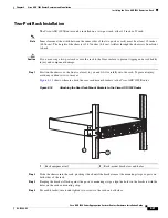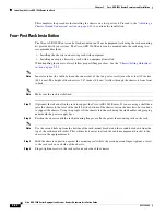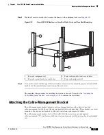
background image


8-34

Cisco ASR 1000 Series Aggregation Services Routers Hardware Installation Guide

OL-13208-09

Chapter 8      Cisco ASR 1002 Router Overview and Installation

Cisco ASR 1002 Router Power Supplies

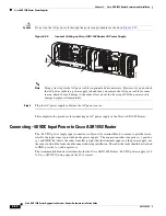
Caution

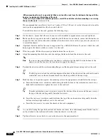
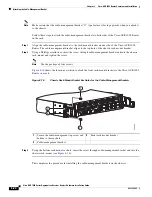
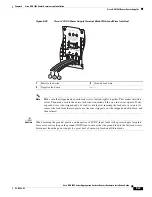
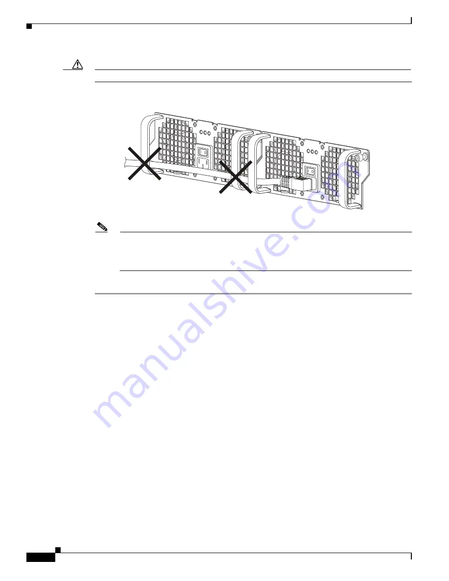
Do not run the AC power cord through the power supply handles as shown in 

Figure 8-25

.

Figure 8-25

Incorrect Cabling on Cisco ASR 1002 Router AC Power Supply 

Note

Using a tie wrap for the AC power cable is optional and not necessary. However, if you do attach 
the AC power cable to a power supply tab and then you remove the AC power cable for some 
reason, check for any damage to the cable after you cut the tie wrap off. If the power cord is 
damaged, replace it immediately.

Step 4

Plug the AC power supply cable into the AC power source.

This completes the procedure for connecting an AC power supply in the Cisco ASR 1002 Router.

Connecting –48 VDC Input Power to Cisco ASR 1002 Router

The –48 VDC power supply input connector is a Euro-style terminal block. A means to provide strain 
relief to the input wires is provided on the power supply.   The connection order is negative (

), positive 

(

+

), and GND; but this is the order from left to right that the terminals appear on the power supply, not 

the order in which the leads should connected during installation. The order the leads should be attached 
is GND, positive (+), and negative (-).

The recommended branch circuit breaker for the Cisco ASR 1002 Router –48 VDC power supply is 30 
A. Use a AWG #10 wire gauge on the 30 A circuit.

280378

OUTPUT INPUT

FAIL

OK

OK

FAN

This unit might ha

ve more than

one power supp

ly connection.

All connections mu

st be removed

to de-energize the 

unit.

OUTPUT INPUT

FAIL

OK

OK

FAN

This unit might ha

ve more than

one power supp

ly connection.

All connections m

ust be removed

to de-ene

rgize the unit.

Содержание ASR1002 - ASR 1002 Router

Страница 1: ...aching the Cable Management Bracket page 8 23 Attaching a Chassis Ground Connection page 8 25 Connecting the Shared Port Adapter Cables page 8 28 Connecting the Console and Auxiliary Port Cables page 8 29 Cisco ASR 1002 Router Power Supplies page 8 30 Connecting a Terminal to the Cisco ASR1000 RP1 Console Port page 8 44 Connecting Cables page 8 46 Auxiliary Connection page 8 46 Cisco ASR 1002 Rout...

Страница 2: ...lies are fixed into the chassis and are not upgradeable but the shared port adapters in the SIP are field upgradable This section contains the following topics Front View page 8 2 Rear View page 8 3 Cisco ASR 1002 Router Slot Numbering page 8 4 Front View Figure 8 1 shows the Cisco ASR 1002 Router with modules installed Figure 8 1 Cisco ASR 1002 Router Front View Note The SPAs in subslots 1 3 are ...

Страница 3: ...T INPUT FAIL OK OK FAN This unit might have more than one power supply connection All connections must be removed to de energize the unit This unit might have more than one power supply connection All connections must be removed to de energize the unit 0 1 8 7 280288 4 1 5 6 3 2 1 Chassis ESD socket 6 DC power supply captive installation screw 2 DC power supply slot 0 label 7 DC power supply slot ...

Страница 4: ...are located in the SPA 0 location and will be addressed as GE 0 0 x The Cisco ASR 1002 Router provides a built in 4 Gigabit Ethernet interface and this SPA is physically located on the Cisco embedded ASR1000 RP1 board The Cisco ASR 1000 Series ESP card is located in slot 1 and labeled as FP0 Figure 8 4 shows the Cisco ASR 1002 Router slot numbering Figure 8 4 Cisco ASR 1002 Router Slot Numbering C...

Страница 5: ...or Cisco ASR 1002 Router Description The Cisco embedded ASR1000 SIP10 in the Cisco ASR 1002 Router is built into the Cisco ASR 1002 Router The Cisco embedded ASR1000 SIP10 provides the physical and electrical termination for up to three half height SPAs or one full height and one half height SPA Double wide SPAs are not supported The fourth SPA slot is connected to the built in 4xGE SPA that resid...

Страница 6: ...ASR 1002 Router The Cisco ASR 1002 Router power supply module supports the following Cisco power supplies AC power supply operates between 85VAC to 264VAC and DC operates between 40 5 to 72VDC 48 VDC power supply operates between 24 VDC power supply operates STBY ACTV STAT ASR1000 ESP10 PWR 280080 4 3 2 1 No LED Label LED Color Behavior in the Power Up State 1 PWR Power Solid green All power suppl...

Страница 7: ...co ASR 1002 Router LED Label LED Color Description INPUT OK Power supply activity Green LED is green and signals that the AC power supply input voltage is greater than 85 V None If LED is not lighted the AC input voltage is less than 70 V or the power supply is turned off For an AC input voltage between 70 V and 85 V the INPUT OK LED can be either on off or flashing FAN OK Power supply fan activit...

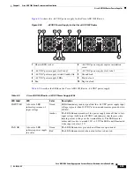
Страница 8: ...GND The DC power supply is secured into the system chassis with two captive screws mounted on the faceplate Figure 8 7 shows the 48 VDC Power Supply for the Cisco ASR 1002 Router Figure 8 7 48 VDC Power Supply for the Cisco ASR 1002 Router 1 Chassis ESD socket 5 AC power supply fan 2 AC power supply slot number 0 6 AC power supply captive installation screw 3 AC power supply On Off O switch 7 AC p...

Страница 9: ...nates green to signal that the DC power supply input voltage is greater than 43 5VDC at turn on and remains green down to 39VDC Amber The LED illuminates amber if the power supply turns off due to low input voltage falls below 39VDC and indicates that there is still a hazard present voltage on the terminal block The LED remains amber and is active to around 20 V 5 V The LED is not illuminated if t...

Страница 10: ...ines and electrical requirements of the supply Use the tie wraps to dress the input cable wires there are two tie wrap tabs on the 24 VDC power supply The 24 VDC power supply unit is secured into the system chassis with two captive screws mounted on the faceplate Figure 8 8 shows the 24 VDC Power Supply for the Cisco ASR 1002 Router Figure 8 8 Cisco ASR 1002 Router 24 VDC Power Supply 1 24 VDC ter...

Страница 11: ...ne variation Total system power consumption should not exceed 470 watts or output rating of each power supply Note Two power supplies are used for redundant operation System total power consumption shall never exceed rating of one power supply to maintain redundancy LED Label LED Color Description OUTPUT FAIL Power supply activity Red When the LED is off it signals that the 24 VDC output voltage a...

Страница 12: ...stress remains within the manufacturer s specified rating Thermal Shutdown The 24 VDC power supply will shut down to protect its components due to excessive internal temperature The 24 VDC power supply then automatically restarts if the internal temperature returns to a safe operating level Installation Methods Cisco ASR 1002 Router is designed for standalone two rail 19 inch rack mount front rail...

Страница 13: ...trip does impair a rack mount installation remove the power strip before installing the chassis and then replace it after the chassis is installed Allow sufficient clearance around the rack for maintenance If the rack is mobile you can push it back near a wall or cabinet for normal operation and pull it out for maintenance installing or moving cards connecting cables or replacing or upgrading comp...

Страница 14: ...d be installed off the floor Dust that accumulates on the floor is drawn into the interior of the router by the cooling fans Excessive dust inside the router can cause overtemperature conditions and component failures There must be approximately 19 inches 48 3 cm of clearance at the front and rear of the chassis to install and replace FRUs or to access network cables and equipment The Cisco ASR 10...

Страница 15: ...ets after the chassis is installed in the rack Step 5 Gather the two cable management brackets and screws shipped with your chassis Figure 8 10 shows cable management brackets attached on the front of the Cisco ASR 1002 Router Note Make certain that the cable management U feature device has the open end pointing upwards when you attach it to the chassis 30007 1 3 2 4 0A PROC ESSOR ONLY 0B 5 6 7 8 ...

Страница 16: ...e the width between the inner sides of the two posts or rails must be at least 19 inches 48 26 cm The height of the chassis is 3 47 inches 8 8 cm Airflow through the chassis is from front to back Note If you are using a two post rack secure the rack to the floor surface to prevent tipping and avoid bodily Four post 19 inch equipment rack Inner clearance the width between the inner sides of the two...

Страница 17: ...pace between the inner edges of the left front and right front mounting flanges on the equipment rack The space must be at least 17 7 inches 45 cm to accommodate the chassis which is 17 25 inches 43 8 cm wide and fits between the mounting posts on the rack Figure 8 11 Verifying Equipment Rack Dimensions Attaching the Chassis Rack Mount Brackets This section explains how to attach the front and rea...

Страница 18: ...t rack mount bracket top hole with the chassis first top hole behind the side vent holes Step 3 Insert and tighten the black screws on one side Step 4 Repeat Step 1 through Step 3 on the other side of the chassis Use black screws to secure the rack mount brackets to the chassis Step 5 Install the chassis in a rack To install the Cisco ASR 1002 Router in a rack go to the Installing the Cisco ASR 10...

Страница 19: ...ASR 1002 Router Caution To make installation easier before you mount the ASR 1002 Router in a rack make certain you read which rack mount bracket ear holes to use when positioning the chassis in the rack As a result of using the designated ear holes on the rack mount bracket the cable management bracket installation will be made easier Installing the Cisco ASR 1002 Router in a Rack After installin...

Страница 20: ...en the rack posts Step 5 Align the mounting bracket holes with the rack post holes and attach the chassis to the rack Note If you are using a shelf then raise the chassis to the level of the shelf Let the bottom of the chassis rest on the brackets but continue to support the chassis Step 6 Position the chassis until the rack mounting flanges are flush against the mounting rails on the rack Tip To ...

Страница 21: ...osest to you and lift it carefully into the rack To prevent injury avoid any sudden twists or moves Figure 8 14 shows where to attach the rear rack mount brackets to the Cisco ASR 1002 Router Figure 8 14 Attaching the Rear Rack Mount Brackets to the Cisco ASR 1002 Router Step 2 Slide the chassis into the rack pushing it back until the brackets meet the mounting strips or posts on both sides of the...

Страница 22: ...e two posts or rails must be at least 19 inches 48 26 cm The height of the chassis is 3 47 inches 8 8 cm Airflow through the chassis is from front to back Note Make sure the rack is stabilized Step 1 Optional Install a shelf in the rack to support the Cisco ASR 1002 Router If you are using a shelf then raise the chassis to the level of the shelf Let the bottom of the chassis rest on the brackets b...

Страница 23: ...o continue the installation Attaching the Cable Management Bracket The cable management brackets mount to each rack mount bracket on the chassis to provide cable management to both sides of the chassis parallel with card orientation These brackets are screw mounted to the rack mount brackets to allow easy installation and removal of cables The cable management brackets for the Cisco ASR 1002 Route...

Страница 24: ...is rack mount and tighten the screw Note Use the package of four screws Figure 8 16 shows the locations at which to attach the front rack mount brackets to the Cisco ASR 1002 Router in a rack Figure 8 16 Chassis Rack Mount Bracket Ear Holes for the Cable Management Brackets Step 3 Using the bottom rack mount ear hole insert the screw through cable management bracket and into the chassis rack mount...

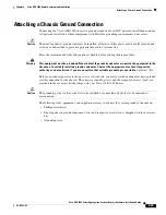
Страница 25: ...quipment must be grounded Never defeat the ground conductor or operate the equipment in the absence of a suitably installed ground conductor Contact the appropriate electrical inspection authority or an electrician if you are uncertain that suitable grounding is available Statement 1024 Before you connect power or turn on power to your chassis you must provide an adequate chassis ground earth conn...

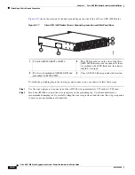
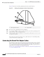
Страница 26: ...he wire receptacle on the grounding lug Use the manufacturers s recommended crimping tool to carefully crimp the wire receptacle around the wire this step is required to ensure a proper mechanical connection ASR 1002 stat pwr min maj crit SPA 4XOC 3 POS STA TUS 0 1 2 3 C A A L C A A L C A A L C A A L SPA 4XOC 3 POS STA TUS 0 1 2 3 C A A L C A A L C A A L C A A L STAT QE0 QE1 QE2 QE3 BOOT CARRIER L...

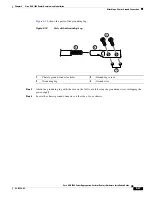
Страница 27: ...nection Figure 8 18 shows the parts of the grounding lug Figure 8 18 Parts of the Grounding Lug Step 3 Attach the grounding lug with the wire on the left to avoid having the grounding wire overlapping the power supply Step 4 Locate the chassis ground connector on the side of your chassis 1 Chassis ground connector holes 3 Ground lug screws 2 Grounding lug 4 Ground wire 50536 1 2 3 4 ...

Страница 28: ... wire to the appropriate grounding point at your site to ensure an adequate chassis ground This completes the procedure for attaching a chassis ground connection Go to the following cabling sections for information on attaching cables Connecting the Shared Port Adapter Cables The instructions for connecting the cables for the shared port adapter installed in the Cisco ASR 1002 Router are contained...

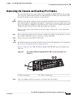
Страница 29: ...le and auxiliary port connectors Before you can use the console interface on the router using a terminal or PC you must perform the following steps Step 1 Before connecting a terminal to the console port configure the terminal to match the chassis console port as follows 9600 baud 8 data bits no parity 1 stop bits 9600 8N1 Step 2 Connect to the port using the RJ 45 to DB 9 cable Note For informati...

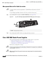
Страница 30: ...ement device or network Cisco ASR 1002 Router Power Supplies This section describes the Cisco ASR 1002 Router power supplies and how to connect them Connecting AC Input Power to Cisco ASR 1002 Router page 8 31 Connecting 48 VDC Input Power to Cisco ASR 1002 Router page 8 34 Connecting Cisco 24 VDC Power Supply page 8 38 Read the safety warnings before you begin Warning The covers are an integral p...

Страница 31: ...tor Contact the appropriate electrical inspection authority or an electrician if you are uncertain that suitable grounding is available Statement 1024 Warning This unit has two power supply connections All connections must be removed to de energize the unit Statement 1028 Warning This product relies on the building s installation for short circuit overcurrent protection Ensure that the protective ...

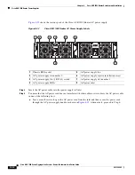
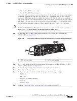
Страница 32: ...ways a Leave a small service loop in the AC power cord from the inlet and then secure the power cord through the AC power supply handle as shown in Figure 8 23 Alternatively proceed to Step b 1 Chassis ESD socket 5 AC power supply fan 2 AC power supply slot number 0 6 AC power supply captive installation screw 3 AC power supply On Off O switch 7 AC power supply slot number 1 4 AC power supply LEDs...

Страница 33: ...l not be disconnected from the AC power inlet as shown in Figure 8 24 Figure 8 24 Cisco ASR 1002 Router AC Power Supply in Slot 0 and Slot 1 With Power Cord 1 AC power cord 280383 OUTPUT INPUT FAIL OK OK FAN This unit might have more than one power supply connection All connections must be removed to de energize the unit 1 280377 OUTPUT INPUT FAIL OK OK FAN This unit might have more than one power...

Страница 34: ...cting an AC power supply in the Cisco ASR 1002 Router Connecting 48 VDC Input Power to Cisco ASR 1002 Router The 48 VDC power supply input connector is a Euro style terminal block A means to provide strain relief to the input wires is provided on the power supply The connection order is negative positive and GND but this is the order from left to right that the terminals appear on the power supply...

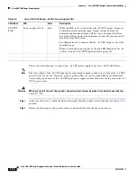
Страница 35: ...st be removed to de energize the unit OUTPUT INPUT FAIL OK OK FAN 48V 60V 16A This unit might have more than one power supply connection All connections must be removed to de energize the unit 9 8 10 4 5 6 3 0 1 7 1 2 Table 8 9 Cisco ASR 1002 Router 48 VDC Power Supply LEDs LED Label LED Color Description INPUT OK A bi color LED indicates presence of input voltage Green LED illuminates green to si...

Страница 36: ...e first and disconnected last Statement 1046 Step 1 At the rear of the router check that the power supply Standby switch is in the Standby see Figure 8 27 position Step 2 Ensure that the negative and positive leads are disconnected from the site power source OUTPUT FAIL Power supply activity Red When the LED is off it signals that the 48 VDC output voltage are within the normal operating range Out...

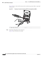
Страница 37: ...le after inserting the lead into its receptacle remove the lead from the receptacle use the wire stripper to cut the stripped end of the lead and repeat Step 3 through Step 5 Step 6 After tightening the receptacle screw for the ground positive and negative 48 VDC input leads use a cable tie to secure the three leads to the power supply faceplate as shown in Figure 8 27 When securing the ground pos...

Страница 38: ... Router 24 VDC power supply is a 40 A UL listed circuit breaker Before you begin read these important notices about the 24 VDC power supply The labeling displays 27 VDC INPUT This labeling describes the nominal voltage provided at a cell site Observe the polarity location Unlike the polarity labels of the 48 VDC power supply ground positive negative the polarity labels on the 24 VDC are ground neg...

Страница 39: ...e made first and disconnected last Statement 1046 To connect 24 VDC power supply in the Cisco ASR 1002 Router follow these steps Step 1 At the rear of the router check that the power Standby switch is in the Standby position Step 2 Ensure that the positive and negative leads are disconnected from the site power source and the source circuit breaker is turned off Step 3 Using a wire stripper strip ...

Страница 40: ...ert the screwdriver at an angle to release the spring while you install the stripped lead wire as shown in Figure 8 30 Figure 8 30 Inserting a Screwdriver Into the 24 VDC Power Supply Terminal Block Step 5 Carefully push the screwdriver at an angle forward until you relieve the spring contact Step 6 With the screwdriver still inserted gently push the lead wire ground lead first in until the copper...

Страница 41: ...e the screwdriver to release the spring to tension down on the installed lead wire then perform these steps a Hold the lead wire in place while you are removing the screwdriver b Once the screwdriver is completely removed gently pull on the lead wire to make certain that the lead wire is securely installed 1 Lead wire insulation 2 Copper wire 253167 OUTPUT INPUT FAIL OK OK FAN This unit might have...

Страница 42: ...crewdriver being removed while you gently pull on the lead wire Figure 8 33 Removing a Screwdriver from the 24 VDC Power Supply Terminal Block Step 8 Repeat Steps 5 through Step 10 for each lead wire Figure 8 34 shows all the lead wires installed 1 Gently pull on lead wire OUTPUT INPUT FAIL OK OK FAN This unit might have more than one power supply connection All connections must be removed to de e...

Страница 43: ...lead is visible after inserting the lead into its receptacle remove the lead from the receptacle use the wire stripper to cut the stripped end of the lead and then reinsert Caution When securing the ground positive and negative 24 VDC input leads to the power supply faceplate leave extra service loop in the ground GND lead to ensure that the ground lead is the last lead wire to disconnect from the...

Страница 44: ...35 item 5 Step 11 Turn on the branch source breaker Step 12 Place the power supply standby switch to the On position The power supply LEDs light when power is supplied to the router This completes the steps for installing the 24 VDC power supply in the Cisco ASR 1002 Router Connecting a Terminal to the Cisco ASR1000 RP1 Console Port The Cisco ASR 1002 embedded router processor has an asynchronous ...

Страница 45: ...ute Processor 1 must have a console port connection typically to a terminal server if you are running a redundant configuration in the chassis Step 1 Connect one end of the RJ 45 cables to the serial RJ 45 port CON on the Cisco embedded ASR1000 RP1 see Figure 8 36 Figure 8 36 Cisco ASR 1002 Router Console Port Connection on Cisco Embedded ASR1000 RP1 Step 2 Run the cable up and through the cable m...

Страница 46: ...m Auxiliary Connection This asynchronous EIA TIA 232 serial port AUX is used to connect a modem to the Cisco ASR 1000 Series Route Processor 1 for remote administrative access Use the following procedure to connect the Cisco ASR 1002 Router to a modem Step 1 Connect one end of the modem cable to the RJ 45 port on the primary Cisco ASR 1000 Series Route Processor 1 labeled AUX For the AUX port conn...

Отзывы: