background image


6-89

Cisco TelePresence System 

OL-16441-01

Chapter 6      Options for the Cisco TelePresence System 3000, 3010, 3200, and 3210

    Upgrading a CTS 3000 to a CTS 3200

Step 2

If your installation uses wired Ethernet for the second row participants, attach the Ethernet cables to the 
modules in the foam bumpers and route the Ethernet cables.

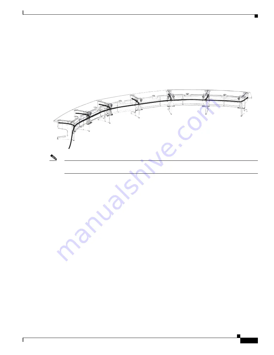
Figure 6-74

Ethernet Cable Routing

Note

The Table Leg Signal cables are routed behind the Display structure, along with the other signal cables, 
but do not plug into any Codec.

204157

Содержание Aironet 1000 Series

Страница 1: ...ystems Inc 170 West Tasman Drive San Jose CA 95134 1706 USA http www cisco com Tel 408 526 4000 800 553 NETS 6387 Fax 408 527 0883 Cisco TelePresence System Hardware Options Upgrade Guide August 5 2009 Text Part Number OL 16441 01 ...

Страница 2: ...rect the interference by using one or more of the following measures Reorient or relocate the receiving antenna Increase the separation between the equipment and receiver Connect the equipment into an outlet on a circuit different from that to which the receiver is connected Consult the dealer or an experienced radio TV technician for help Modifications to this product not authorized by Cisco coul...

Страница 3: ... a Auxiliary Control Unit 2 15 Configuring a Cisco TelePresence Presentation Codec 2 15 Options for the Cisco TelePresence System 1000 3 1 Auxiliary Control Unit 3 1 Parts List for Auxiliary Control Unit 3 1 Adding an Auxiliary Control Unit 3 2 Adding an Auxiliary Control Unit with a Cisco TelePresence Presentation Codec 3 5 Configuring an Auxiliary Control Unit 3 5 Cisco TelePresence Presentation...

Страница 4: ...entation Codec 6 6 Cisco TelePresence Presentation Codec 6 6 Parts List for Presentation Codec 6 6 Adding a Cisco TelePresence Presentation Codec Cisco TelePresence System 3000 and 3200 6 7 Adding a Cisco TelePresence Presentation Codec Cisco TelePresence System 3010 and 3210 6 19 Configuring a Cisco TelePresence Presentation Codec 6 24 Adding a Cisco TelePresence Presentation Codec with a Auxilia...

Страница 5: ...Contents v Cisco TelePresence System OL 16441 01 Parts List 7 12 Attaching and Routing Cables 7 61 Powering On the System 7 69 ...

Страница 6: ...Contents vi Cisco TelePresence System OL 16441 01 ...

Страница 7: ...nel may also find this document useful Conventions This document uses the following conventions to convey information and alert the user to conditions requiring special awareness Warning This warning symbol means danger You are in a situation that could cause bodily injury Before you work on any equipment you must be aware of the hazards involved with electrical circuitry and familiar with standar...

Страница 8: ...setup configuration administration and use of the Cisco TelePresence These documents include Cisco TelePresence System 1000 Assembly Use Care and Field Replacement Unit Guide OL 16247 01 There is also a pointer document for this guide 78 17800 02 Cisco TelePresence System 3000 Assembly Use Care and Field Replacement Unit Guide OL 16246 01 There is also a pointer document for this guide 78 17795 02...

Страница 9: ...t that enables digital signage and Enterprise TV through the ability to play high definition live and on demand video motion graphics Web and dynamic content on digital displays For more information about the DMP refer to this URL http www cisco com en US products ps7220 tsd_products_support_series_home html Note If you use a Cisco TelePresence Touch device with your CTS 500 32 system you have add...

Страница 10: ...er 1 Options for the Cisco TelePresence System 500 32 Cisco Digital Media Player To configure the CTS 500 32 system for use with the DMP complete the following steps Step 1 Remove the rear codec cover Figure 1 1 Removing the Rear Codec Cover 209093 ...

Страница 11: ...DMP in Figure 1 2 Figure 1 2 Codec Connections 208938 Microphone Table Microphone is not supported Line out Audio Output Auto Collaborate Display Video PC Audio PC Video To Network To Phone Power Auxiliary PC Audio Auxiliary Input ex DMP DocumentCamera To DocumentCamera Speaker Microphone Main Camera Control Main Camera Video Main Display Video Main Camera Power Connectto DisplayStand I O Panel Co...

Страница 12: ...tand Note If you want to share a presentation use the VGA and if required audio connections labeled PC that are shown as callouts 7 and 8 in Figure 1 3 Figure 1 3 Connections at the Foot of the Column or Table Stand Note If you use a Cisco Unified IP Phone as your call control device and you have a document camera and a Cisco Digital Media Player DMP connected to the CTS 500 32 and the document ca...

Страница 13: ...r more information about the DMP refer to this URL http www cisco com en US products ps7220 tsd_products_support_series_home html To configure the DMP audio for use with Cisco TelePresence refer to the Testing the LEDs and Light Fixture and Configuring the Digital Media Player Audio section of the First Time Setup chapter of the Cisco TelePresence System 500 Assembly Use Care and Field Replaceable...

Страница 14: ...yer Step 1 Connect the video for the DMP to the Digital Media Player DMP HD video connection on the CTS 500 display See Figure 2 1 for the connection Figure 2 1 HD Video Connection for Digital Media Player 205035 On Off switch Microphone Lower rear Digital Media Player DMP Optional HD Video primary input AC inlet Microphone ...

Страница 15: ...re for correct functioning with the CTS 500 complete the following steps Step 1 Log into the CIsco TelePresence System administrative GUI Step 2 Navigate to Troubleshooting Hardware Setup Other Devices DMS Step 3 Click the Other Devices radio button Step 4 Click the DMS tab Step 5 Check the Enable DMS check box Camera Document Camera optional IP Phone Network Left Speaker Right Speaker External Pr...

Страница 16: ...t all times that the DMP source is active including during a conference and during non business hours Select this option if you want to share audio from the DMP source during a conference Step 5 To end DMP audio configuration click Stop The CTS 500 retains the setting that you specify in this procedure If you encounter problems when setting up the devices in this section refer to the Troubleshooti...

Страница 17: ...cted to the network c In the URL field type the IP address for the system codec and press Enter The browser launches the Cisco TelePresence System Administrator d In the Admin field type admin e In the Password field type cisco Note If your administrator has changed the user name or password enter those values f Click Login g Locate the Phone pane in the upper left hand corner of the administrator...

Страница 18: ...s one through six appear at the bottom of the display screen on the left hand side i After the first number changes to a check mark unplug the system power cord from the wall socket Step 7 Remove the presentation codec from its packaging Step 8 Remove the right handle mounting bracket from the presentation codec Figure 2 3 Removing the Right Handle Mounting Bracket Note Place the codec and base so...

Страница 19: ...ions for the Cisco TelePresence System 500 37 Cisco TelePresence Presentation Codec Step 9 Insert the tab of the rear cover in the slot between the left handle mounting bracket and the codec Figure 2 4 Rear Cover and Left Handle Mounting Bracket 1 3 204586 ...

Страница 20: ...er 2 Options for the Cisco TelePresence System 500 37 Cisco TelePresence Presentation Codec Step 10 Insert the lower part of the left handle mounting bracket into the mounting base Figure 2 5 Left Handle Mounting Bracket and Mounting Base 1 4 204587 ...

Страница 21: ...c by performing one of the following actions For a pedestal stand mounted CTS 500 lift and remove the codec cover See Figure 2 14 for more information For a wall mounted or table stand mounted CTS 500 remove the codec handle slide the codec to the center and disconnect the codec from the base Tip Removal is the opposite of installation it can be helpful to review the codec installation instruction...

Страница 22: ...cables between the CTS 500 and presentation codec Figure 2 7 shows you the cabling diagram for a CTS 500 with a presentation codec Figure 2 7 Power and Signal Cabling for Presentation Codec 205705 Microphone Speaker Codec Presentation Codec Auxiliary Video Out Camera IP Phone Signal Network Document Camera Display Auxiliary Video In Signal Auxiliary Video In Video out ...

Страница 23: ...hared presentations Connect the presentation source to the codec using the DVI to VGA cable plug the DVI connection into the Auxiliary Video In connection Figure 2 8 Cabling Diagram CTS 500 with Presentation Codec and External Presentation Display 205706 Microphone Speaker Codec External Presentation Display Presentation Codec Auxiliary Video Out Camera IP Phone Signal Network Document Camera Disp...

Страница 24: ...stem OL 16441 01 Chapter 2 Options for the Cisco TelePresence System 500 37 Cisco TelePresence Presentation Codec Step 14 Place the left end cap on the presentation codec assembly Figure 2 9 Left End Cap 204589 5 9 View A View A ...

Страница 25: ...s through the hole in the rear center of the cover Note The hole for the cables is not visible in Figure 2 10 it faces the rear of the codec Tip If your installation does not have enough space behind the codec to route the cables through the hole in the top cover route the cables through either the left or right end cap Note Tighten the screws until they are snug but do not overtighten Figure 2 10...

Страница 26: ...ews until they are snug but do not overtighten Figure 2 11 Right End Cap Step 17 Power on the CTS 500 system Note You might have to reboot your presentation codec several times before it becomes active For information about rebooting the CTS 500 refer to the Field Replacement and Upgrade Disassembly Instructions chapter of the Cisco TelePresence 500 Assembly Use Care and Field Replacement Unit Gui...

Страница 27: ...presentation codec Note The Ethernet ports in the auxiliary control unit are interchangeable Use either of the ports for the connections from the primary codec and the presentation codec Configuring a Cisco TelePresence Presentation Codec To configure the presentation codec with the CTS 500 complete the following steps Step 1 Log in to the Cisco Unified Communications Manager web GUI Step 2 Naviga...

Страница 28: ...2 16 Cisco TelePresence System OL 16441 01 Chapter 2 Options for the Cisco TelePresence System 500 37 Cisco TelePresence Presentation Codec ...

Страница 29: ... ports and an incoming and outgoing Ethernet connection that allows you to control peripheral items The auxiliary control unit is controlled by your CTS 1000 Administrator and can be configured to Turn the CTS 1000 lights on during a Cisco TelePresence call and turn the lights off after the call completes or to stay on for a period of time after a call completes Turn the CTS 1000 lights on accordi...

Страница 30: ...eting the following steps a Remove the black speaker grille from the top of the front panel by grasping the sides until the pins pop out of the holes b Using a 3 Phillips screwdriver remove the six screws next to the speaker three on either side c Pull the front panel away from the frame d Disconnect the lighting unit from the PDU Figure 3 1 Removing the Front Panel From the Frame 8 M5 x 10mm pan ...

Страница 31: ...he Ethernet cable to the auxiliary control unit as follows Connect the Primary Codec Document Camera Ethernet connection orange Ethernet connection on the primary codec to one Ethernet port of the auxiliary control unit Connect the other Ethernet port of the auxiliary control unit to the Presentation Codec Ethernet port white red Ethernet connection on the presentation codec Step 5 Measure and dri...

Страница 32: ...ews and drywall anchors that are provided with the kit There are two screws on each side Mount the unit directly below the horizontal metal support for the display stand and make sure that the Ethernet connections are pointing upwards and the power connections are pointing downwards You must connect the Ethernet cables if they are used to the unit before you mount it 204198 9 1 Ethernet cables ...

Страница 33: ...ding an Auxiliary Control Unit section on page 3 2 and add the following additional connections Connect the Primary Codec Document Camera Ethernet connection orange Ethernet connection on the primary codec to one Ethernet port of the auxiliary control unit Connect the other Ethernet port of the auxiliary control unit to the Presentation Codec Ethernet port white red Ethernet connection on the pres...

Страница 34: ...ted to the network c In the URL field type the IP address for the system codec and press Enter The browser launches the Cisco TelePresence System Administrator d In the Admin field type admin e In the Password field type cisco Note If your administrator has changed the user name or password enter those values f Click Login g Locate the Phone pane in the upper left hand corner of the administrator ...

Страница 35: ...ne through six appear at the bottom of the display screen on the left hand side i After the first number changes to a check mark unplug the system power cord from the wall socket Step 11 Remove the presentation codec from its packaging Step 12 Remove the right handle mounting bracket from the presentation codec Figure 3 3 Removing the Right Handle Mounting Bracket Note Place the codec and base so ...

Страница 36: ...tions for the Cisco TelePresence System 1000 Cisco TelePresence Presentation Codec Step 13 Insert the tab of the rear cover in the slot between the left handle mounting bracket and the codec Figure 3 4 Rear Cover and Left Handle Mounting Bracket 1 3 204586 ...

Страница 37: ...ter 3 Options for the Cisco TelePresence System 1000 Cisco TelePresence Presentation Codec Step 14 Insert the lower part of the left handle mounting bracket into the mounting base Figure 3 5 Left Handle Mounting Bracket and Mounting Base 1 4 204587 ...

Страница 38: ... Chapter 3 Options for the Cisco TelePresence System 1000 Cisco TelePresence Presentation Codec Step 15 Reattach the right handle mounting bracket to the codec assembly Figure 3 6 Right Handle Mounting Bracket and Codec Assembly 2 1 8 8 204588 ...

Страница 39: ... frame Complete the following steps a Remove the black speaker grille from the top of the front panel by grasping the sides until the pins pop out of the holes b Using a 3 Phillips screwdriver remove the six screws next to the speaker three on either side c Pull the front panel away from the frame d Disconnect the lighting unit from the PDU Figure 3 7 Removing the Front Panel From the Frame 200264...

Страница 40: ...l unit that is marked UNSWITCHED Note If your CTS 1000 does not have an auxiliary control unit route the Ethernet cables for the Primary Codec Signal connection directly between the codec and presentation codec If your CTS 1000 has an auxiliary control unit you must disconnect it from the wall to make the Ethernet connections Figure 3 8 Power and Signal Cabling for Presentation Codec 205659 1 2 1 ...

Страница 41: ...red presentations Note If your CTS 1000 does not have an auxiliary control unit omit the video connection between the presentation display and the auxiliary control unit Figure 3 9 Cabling Diagram CTS 1000 with External Presentation Display 205661 Microphone Speaker Codec Auxiliary Video Out Camera IP Phone Primary Codec Signal Network Document Camera Display Auxiliary Video In Video In External P...

Страница 42: ...y control unit Plug the codec into either the PDU an electrical outlet or the single outlet on the auxiliary control unit that is marked UNSWITCHED Note If your CTS 1000 does not have an auxiliary control unit route the Ethernet cables for the Primary Codec signal directly between the codec and presentation codec and omit the DVI to Serial connection between the external presentation display and t...

Страница 43: ...stem OL 16441 01 Chapter 3 Options for the Cisco TelePresence System 1000 Cisco TelePresence Presentation Codec Step 18 Place the left end cap on the presentation codec assembly Figure 3 11 Left End Cap 204589 5 9 View A View A ...

Страница 44: ... through the hole in the rear center of the cover Note The hole for the cables is not visible in Figure 3 12 it faces the rear of the codec Tip If your installation does not have enough space behind the codec to route the cables through the hole in the top cover route the cables through either the left or right end cap Note Tighten the screws until they are snug but do not overtighten Figure 3 12 ...

Страница 45: ...our presentation codec several times before it becomes active For information about rebooting the CTS 1000 refer to the Field Replacement and Upgrade Disassembly Instructions chapter of the Cisco TelePresence 1000 Assembly Use Care and Field Replacement Unit Guide Adding a Cisco TelePresence Presentation Codec with a Auxiliary Control Unit To add a presentation codec to an CTS 1000 with an auxilia...

Страница 46: ...om the primary codec and the presentation codec Configuring a Cisco TelePresence Presentation Codec To configure the presentation codec for the CTS 1000 complete the following steps Step 1 Log in to the Cisco Unified Communications Manager web GUI Step 2 Navigate to Device Phone Step 3 Find the Cisco Unified IP Phone that controls your Cisco TelePresence system by clicking Find Step 4 Click the hy...

Страница 47: ...n about the DMP refer to this URL http www cisco com en US products ps7220 tsd_products_support_series_home html You can use DMPs with the Cisco Digital Media System DMS For more information about the DMS refer to this URL http www cisco com en US products ps6681 products_documentation_roadmaps_list html The DMS uses Digital Media Manager DMM software For more information about DMM software and DM...

Страница 48: ...nce System 1100 Cisco Digital Media Player Step 1 Connect the video for the DMP to the Digital Media Player DMP HD video connection on the CTS 1100 display See Figure 4 1 for the connection Figure 4 1 HD Video Connection for Digital Media Player 208400 Codec DMP On Off Switch AC inlet ...

Страница 49: ...e for correct functioning with the CTS 1100 complete the following steps Step 1 Log into the CIsco TelePresence System administrative GUI Step 2 Navigate to Troubleshooting Hardware Setup Other Devices DMS Step 3 Click the Other Devices radio button Step 4 Click the DMS tab Step 5 Check the Enable DMS check box Camera Document Camera optional IP Phone Network Left Speaker Right Speaker External Pr...

Страница 50: ... all times that the DMP source is active including during a conference and during non business hours Select this option if you want to share audio from the DMP source during a conference Step 5 To end DMP audio configuration click Stop The CTS 1100 retains the setting that you specify in this procedure If you encounter problems when setting up the devices in this section refer to the Troubleshooti...

Страница 51: ... cover by holding it from underneath and raising it slightly then grasp it from the top and gently rock it towards you to disengage it from the slots in the upper part of the cabinet See Figure 4 5 for more information Step 2 Turn off the power by turning the switch in the PDU that is inside of the cabinet to the OFF position Note This switch is located near the cabinet cover in the lower front of...

Страница 52: ...utlet is on the right as shown in Figure 4 3 Note that the Cisco logo is hidden and the perforated grill on the codec faces the left side of the display cabinet b Slide the codec from the right to the left until the top of the codec slides past the spring loaded posts inside the cabinet Note In some cases you might have to lift the posts and turn them counter clockwise prior to installation c Turn...

Страница 53: ...the Cisco TelePresence System 1100 Cisco TelePresence Presentation Codec Step 4 Attach the cables to the presentation codec and auxiliary display by following the cabling diagram in Figure 4 4 Figure 4 4 Cabling Diagram for Presentation Codec With Auxiliary Display ...

Страница 54: ...creens This is the address of the primary codec unit Step 6 Attach the cabinet cover to the cabinet by completing the following steps a Set the lower part of the cabinet cover into the slotted groove in the lower part of the cabinet b Align the tabs in the upper part of the cabinet cover with the slots in the upper part of the cabinet c Rock the cover forward until the tabs go into the slots Tip I...

Страница 55: ...4 9 Cisco TelePresence System OL 16441 01 Chapter 4 Options for the Cisco TelePresence System 1100 Cisco TelePresence Presentation Codec Figure 4 5 Attaching the Cabinet Cover to the Cabinet 205997 1 ...

Страница 56: ...Trust List CTL from your system by clicking Delete CTL Step 13 In the Use Configuration TFTP Server area click Automatic to set TFTP conditions to their default value and remove any alternate TFTP servers Note Note If you encounter problems you might have to reboot your presentation codec several times before it becomes active To reboot the presentation codec turn off and on the PDU where you plug...

Страница 57: ...n about the DMP refer to this URL http www cisco com en US products ps7220 tsd_products_support_series_home html You can use DMPs with the Cisco Digital Media System DMS For more information about the DMS refer to this URL http www cisco com en US products ps6681 products_documentation_roadmaps_list html The DMS uses Digital Media Manager DMM software For more information about DMM software and DM...

Страница 58: ...nce System 1300 Cisco Digital Media Player Step 1 Connect the video for the DMP to the Digital Media Player DMP HD video connection on the CTS 1300 display See Figure 5 1 for the connection Figure 5 1 HD Video Connection for Digital Media Player 208400 Codec DMP On Off Switch AC inlet ...

Страница 59: ...e for correct functioning with the CTS 1300 complete the following steps Step 1 Log into the CIsco TelePresence System administrative GUI Step 2 Navigate to Troubleshooting Hardware Setup Other Devices DMS Step 3 Click the Other Devices radio button Step 4 Click the DMS tab Step 5 Check the Enable DMS check box Camera Document Camera optional IP Phone Network Left Speaker Right Speaker External Pr...

Страница 60: ...MP source is active including during a conference and during non business hours Select this option if you want to share audio from the DMP source during a conference Step 5 To end DMP audio configuration click Stop The CTS 1300 retains the setting that you specify in this procedure If you encounter problems when setting up the devices in this section refer to the Troubleshooting the Cisco TelePres...

Страница 61: ... cover by holding it from underneath and raising it slightly then grasp it from the top and gently rock it towards you to disengage it from the slots in the upper part of the cabinet See Figure 5 5 for more information Step 2 Turn off the power by turning the switch in the PDU that is inside of the cabinet to the OFF position Note This switch is located near the cabinet cover in the lower front of...

Страница 62: ...utlet is on the right as shown in Figure 5 3 Note that the Cisco logo is hidden and the perforated grill on the codec faces the left side of the display cabinet b Slide the codec from the right to the left until the top of the codec slides past the spring loaded posts inside the cabinet Note In some cases you might have to lift the posts and turn them counter clockwise prior to installation c Turn...

Страница 63: ...Presence Presentation Codec Step 4 Attach the cables to the presentation codec and auxiliary display by following the cabling diagram in Figure 5 4 Note Ignore the connections for the microphone camera and speakers in the following diagram Figure 5 4 Cabling Diagram for Presentation Codec With External Display ...

Страница 64: ...creens This is the address of the primary codec unit Step 6 Attach the cabinet cover to the cabinet by completing the following steps a Set the lower part of the cabinet cover into the slotted groove in the lower part of the cabinet b Align the tabs in the upper part of the cabinet cover with the slots in the upper part of the cabinet c Rock the cover forward until the tabs go into the slots Tip I...

Страница 65: ...5 9 Cisco TelePresence System OL 16441 01 Chapter 5 Options for the Cisco TelePresence System 1300 Cisco TelePresence Presentation Codec Figure 5 5 Attaching the Cabinet Cover to the Cabinet 205997 1 ...

Страница 66: ...Trust List CTL from your system by clicking Delete CTL Step 13 In the Use Configuration TFTP Server area click Automatic to set TFTP conditions to their default value and remove any alternate TFTP servers Note Note If you encounter problems you might have to reboot your presentation codec several times before it becomes active To reboot the presentation codec turn off and on the PDU where you plug...

Страница 67: ...owering the Cisco TelePresence System lights projector and optional peripherals on and off There is one power inlet five controlled power outlets and one power outlet that is not controlled unswitched In addition there are two serial ports one of which allows you to control the power for the projector and incoming and outgoing Ethernet connections that allow you to control an additional peripheral...

Страница 68: ...cription Part Number Qty Notes Audio Video Expansion Unit CTS LIGHT CTRL 69 1989 01 1 Auxiliary Control Unit 69 1989 01 1 2 Bracket for auxiliary control unit 700 27073 01 2 3 Cat6 Ethernet Cable 3M 37 0887 02 2 4 Cat6 Ethernet Cable 1M 37 0901 01 2 5 Serial Cable 6M 37 0980 01 1 6 Cable Tie 51 4641 01 25 7 Cable Holder 1 inch x 1 inch 51 4712 01 25 35 M5 x 10mm pan head screws 48 0426 01 5 ...

Страница 69: ...lePresence system Step 1 Turn off the power to the side PDUs and unplug the power cables for the lighting assembly Figure 6 1 PDU Location and Lighting Assembly Cable Routing Note Your installation might differ from this diagram There might be one PDU on the left side of the display structure rather than two in addition there might be a PDU in the center rear of the display structure Note The term...

Страница 70: ...3210 Auxiliary Control Unit Step 2 Attach the auxiliary control unit to the rear of the display assembly Figure 6 2 Auxiliary Control Unit Note If your installation has a PDU in the center of the display assembly roughly in the same location as the auxiliary control unit remove the PDU during this step 1 35 204148 ...

Страница 71: ...when you connect the serial cable to the projector remove the projector from the table by completing the steps in the Replacing the Projector section in the Field Replaceable Unit Guide chapter of the Cisco TelePresence System 3000 Assembly Use Care and Field Replacement Unit Guide Primary Codec 1 2 1 2 10 100NETW ORK PORTS RESET SERI ALPORTS TelePresence 3 DEF 6 MNO 9 WXYZ 2 ABC 5 JKL 8 TUV 0 OPE...

Страница 72: ...on codec Note The Ethernet ports in the auxiliary control unit are interchangeable Use either of the ports for the connections from the primary codec and the presentation codec Cisco TelePresence Presentation Codec The Cisco TelePresence Presentation Codec CTS HFR COLLAB provides 30 frames per second capabilities to support full motion video presentations between Cisco TelePresence endpoints This ...

Страница 73: ...position Note If there is an additional PDU that is mounted on the rear of the center display structure power off that PDU also Caution Make sure all system power is turned off before beginning this disassembly Figure 6 4 PDU Location Note Your installation might differ from this diagram There might be one PDU on the left side of the display structure rather than two in addition there might be a P...

Страница 74: ... The terms left and right refer to the system as you face it from the front Step 2 Remove the projector screen The projector screen is attached to the Cisco TelePresence assembly by clips that are on the top edge and side of the screen To remove the screen gently pull outward on the screen where the clips are located Figure 6 5 Projector screen Assembly 204189 ...

Страница 75: ...er 6 Options for the Cisco TelePresence System 3000 3010 3200 and 3210 Cisco TelePresence Presentation Codec Step 3 Remove the three speaker assemblies If required disconnect the speaker cables Figure 6 6 Removing the Speaker Assemblies 204190 6 3 2 ...

Страница 76: ...ptions for the Cisco TelePresence System 3000 3010 3200 and 3210 Cisco TelePresence Presentation Codec Step 4 Unscrew the four screws that attach the codec safety tray to the frame feet and remove the codec tray Figure 6 7 Removing Codec Safety Tray 204186 ...

Страница 77: ...L 16441 01 Chapter 6 Options for the Cisco TelePresence System 3000 3010 3200 and 3210 Cisco TelePresence Presentation Codec Step 5 Attach the cable management bar to the presentation codec Figure 6 8 Cable Management Bar 1 5 3 201175 ...

Страница 78: ...hapter 6 Options for the Cisco TelePresence System 3000 3010 3200 and 3210 Cisco TelePresence Presentation Codec Step 6 Attach the attachment brackets to the presentation codec Figure 6 9 Presentation Codec and Attachment Brackets 204187 5 3 4 1 ...

Страница 79: ...r 6 Options for the Cisco TelePresence System 3000 3010 3200 and 3210 Cisco TelePresence Presentation Codec Step 7 Place the double wide codec tray in between the frame feet and secure it with the screws Figure 6 10 Double Wide Codec Tray 204188 2 5 6 ...

Страница 80: ...lePresence System 3000 3010 3200 and 3210 Cisco TelePresence Presentation Codec Step 8 Place the presentation codec in the front of the new codec tray and attach it to the front feet of the display stand Figure 6 11 Presentation Codec and Display Stand Front Feet 5 5 204193 4 3 ...

Страница 81: ...diagram for the presentation codec Figure 6 12 Cable Routing for Presentation Codec and Auxiliary Control Unit 204192 1 2 1 2 10 100NETW ORK PORTS RESET SERI ALPORTS Primary Codec Auxiliary Control Unit Projector Presentation Codec Auxiliary Video Out Camera IP Phone Auxiliary network port Network Left Right Document Camera Left Codec Right Codec Center Display Auxiliary Video In Auxiliary Video I...

Страница 82: ...presentation codec If you have an Auxiliary Control Unit substitute the signal cabling between the presentation codec and the primary codec with the alternate cabling for the Auxiliary Control Unit For a list of the external displays that Cisco TelePresence supports refer to the Release Notes for Cisco TelePresence System for your software release Note When you use the audio video extension unit a...

Страница 83: ...ument Camera Signal Document Camera Video Out Primary Codec Audio Video Expansion Unit Projector External Display Document Camera Presentation Codec Auxiliary Video Out Camera IP Phone Auxiliary network port Network Left Right First Row Center Microphone Document Camera Video In Left Codec Right Codec Center Display Auxiliary Video In Document Camera Signal Auxiliary Video In Video Out Video In Vi...

Страница 84: ... power cables for the presentation codec Figure 6 14 Presentation Codec Cable Routing Note Your installation might differ from this diagram There might be one PDU on the left side of the display structure rather than two in this case connect the PDU to either of the PDUs on the left Note The terms left and right refer to the system as you face it from the front Power 204191 ...

Страница 85: ... Information Configuration CUCM settings window then perform the following actions a In the Certificate Trust List CTL area delete the Certificate Trust List CTL from your system by clicking Delete CTL b In the Use Configuration TFTP Server area click Automatic to set TFTP conditions to their default value and remove any alternate TFTP servers Note If you encounter problems you might have to reboo...

Страница 86: ...6 20 Cisco TelePresence System OL 16441 01 Chapter 6 Options for the Cisco TelePresence System 3000 3010 3200 and 3210 Cisco TelePresence Presentation Codec Figure 6 15 PDU Location Power 201185 ...

Страница 87: ... and set it aside Note If necessary disconnect the cables from the primary codec Figure 6 16 Removing the Center Codec Step 3 Insert the presentation codec in the center tray in front of the codec and attach it to the display stand Attachment of the codec is exactly the same as the primary codec Note Insert the codec so that the logo faces the front of the system facing the users not the wall 2070...

Страница 88: ...r multiple video displays use the following wiring diagram for the presentation codec If you have an Auxiliary Control Unit substitute the signal cabling between the presentation codec and the primary codec with the alternate cabling for the Auxiliary Control Unit 206987 1 2 1 2 10 100 NETW O RK PO RTS RESET SER I AL PO RTS Presentation display Primary Codec Auxiliary Control Unit Presentation Cod...

Страница 89: ...IAL P O RTS Document Camera Signal Document Camera Video Out Primary Codec Audio Video Expansion Unit External Display Optional Presentation display Document Camera Optional Auxiliary Video Out Camera IP Phone Auxiliary network port Network First Row Center Microphone Document Camera Video In Left Codec Right Codec Display Auxiliary Video In Video In Video In Video Out Video In Audio Expansion Uni...

Страница 90: ...the Cisco Unified Communications Manager web GUI Step 2 Navigate to Device Phone Step 3 Find the Cisco Unified IP Phone that controls your Cisco TelePresence system by clicking Find Step 4 Click the hypertext link next to the phone that controls your Cisco TelePresence System to select it Step 5 In the Optional Hardware area click the Presentation Codec check box Figure 6 19 Presentation Codec Che...

Страница 91: ...rt of the projector and the Serial 1 port of the auxiliary control unit See Figure 6 13 for more information Optional Switch for Ethernet Connectivity The optional 18 port switch allows all second participants to have Ethernet connectivity via the table leg Ethernet connections Parts List for Ethernet Connectivity Switch Key Part Description Part Number Qty Notes 1 Switch bracket rear right 700 23...

Страница 92: ...12 ports for the second row of tables Video Signal Splitter The following video signal splitters have been tested for use with Cisco TelePresence systems Note Using External Devices with Your Cisco TelePresence System Cisco cannot guarantee the performance of any external device so Cisco recommends that you choose good quality external devices to optimize performance of the Cisco TelePresence syst...

Страница 93: ...ssing EDID switches the LED light on the front between Int and Ext Set the EDID to Ext and connect the projector to the connector labeled HDMI 1 Connect any auxiliary displays to subsequent outputs The manual for this product is located at http www gefen com pdf EXT HDMI1 3 144 pdf GEFEN GTV HDMI1 3 144 This model is similar to the EXT HDMI1 3 144 and has two buttons on the back labeled Reset and ...

Страница 94: ...place the lenses in the camera cluster with the lenses for the CTS 3200 See the Removing and Replacing the Camera Lenses section on page 6 33 for more information Step 4 Add the audio video extension unit to the rear of the display assembly See the Adding the Audio Video Extension Unit section on page 6 35 for more information Step 5 Add the auxiliary control unit to the rear of the display assemb...

Страница 95: ...key Note If you cannot locate the Manual button proceed to Step b b Locate Info at the bottom of the screen and press the Info soft key c Scroll down to the IP Address listing and copy the address Step 2 Open a browser on a computer that is connected to the network Step 3 In the URL field type the IP address for the primary codec and press Enter The browser launches the Cisco TelePresence System A...

Страница 96: ...he existing primary codec with the new primary codec complete the following steps Step 1 Remove all cable ties holding the cables to the cable management bar Take note of the organization of the cables Step 2 Remove the cables from the codec Label each cable with masking tape for identification as it is removed Step 3 Remove and retain the screws that attach the codec s L brackets to the Display s...

Страница 97: ...OL 16441 01 Chapter 6 Options for the Cisco TelePresence System 3000 3010 3200 and 3210 Upgrading a CTS 3000 to a CTS 3200 Step 8 Attach the cable management bar to the new primary codec Figure 6 21 Cable Management Bar 1 5 3 201175 ...

Страница 98: ... codec into the display stand from the rear of the display assembly and secure it with the screws Step 11 Re attach the cables for the primary codec Note You connect the cables to the new primary codec the same as the existing primary codec with the exception of the left and right microphone cables You attach those cables to the audio video extension unit in the Attaching and Routing Cables sectio...

Страница 99: ...ake care not to scratch or mar the display screen during the replacement procedure Note The directions left and right refer to the assembly as you face it Caution Make sure all system power is turned off before beginning this disassembly Step 1 Remove the top camera hood by removing the screws that secure it to the bracket Step 2 Remove the lens hood by removing the two screws on the bottom of the...

Страница 100: ...ding a CTS 3000 to a CTS 3200 Step 3 Carefully unscrew the lenses from the camera assembly Figure 6 22 Removing Lenses from The Camera Assembly Step 4 Attach the new lenses to the camera assembly Tighten until the lenses are seated and finger tight but do not overtighten Step 5 Re attach the camera hood and lens hood 204199 ...

Страница 101: ...the audio video extension unit for the Cisco TelePresence 3000 you need the following tools and equipment Large Phillips head screwdriver Remove and replace the audio video extension unit by completing the following steps Step 1 Remove the audio video extension unit from its packaging Step 2 Attach the audio video extension unit to its bracket Figure 6 23 Audio Extension Unit and Bracket 204183 2 ...

Страница 102: ... 3010 3200 and 3210 Upgrading a CTS 3000 to a CTS 3200 Step 3 Attach the audio video extension unit to the display assembly Figure 6 24 Audio Extension Unit and Display Assembly Step 4 Attach the new extension unit to the display structure with the screws that are provided in the package 35 1 204147 ...

Страница 103: ...auxiliary control unit bypass this procedure To add the auxiliary control unit Cisco TelePresence 3000 you need the following tools and equipment Large Phillips head screwdriver Masking tape Remove and replace the audio video extension unit by performing the following procedure Step 1 Remove the auxiliary control unit from its packaging Step 2 Attach the auxiliary control unit to its bracket using...

Страница 104: ...or the Cisco TelePresence System 3000 3010 3200 and 3210 Upgrading a CTS 3000 to a CTS 3200 Step 3 Attach the auxiliary control unit to the rear of the display assembly with the screws that are provided in the package Figure 6 25 Auxiliary Control Unit 1 35 204148 ...

Страница 105: ... Assembly To build the second row table assembly complete the following procedure Use the provided parts list as a guide for the illustrations in this section Parts List For the latest version of the parts list refer to the Parts List section in the Building the Second Row Table Assembly chapter of the Cisco TelePresence System 3200 Assembly Use Care and Field Replacement Unit Guide ...

Страница 106: ...r 6 Options for the Cisco TelePresence System 3000 3010 3200 and 3210 Upgrading a CTS 3000 to a CTS 3200 Step 1 Remove the Metal packaging braces from the Molded foam bumpers Figure 6 26 Metal packaging braces and their Molded foam bumpers 201152 3 2 ...

Страница 107: ...ptions for the Cisco TelePresence System 3000 3010 3200 and 3210 Upgrading a CTS 3000 to a CTS 3200 Step 2 Assemble the seven Molded foam bumpers and the seven Table leg bases Figure 6 27 Four Molded foam bumpers and the four Table leg bases 204149 3 37 1 ...

Страница 108: ...le legs Figure 6 28 Gutter and Privacy Panel Support Brackets Type 1 Note Note the table layout Each section is numbered as shown in Figure 6 28 Each cable gutter and privacy panel is different The numbering for the cable gutters and privacy panels correspond to the numbering for the table top Tip When you attach the support brackets it can be helpful to turn the table leg upside down 4 4 35 35 20...

Страница 109: ...ng a CTS 3000 to a CTS 3200 Step 4 Attach the second set of five support brackets to the table legs Figure 6 29 Gutter and Privacy Panel Support Brackets Type 2 Tip When you attach the support brackets it can be helpful to turn the table leg upside down 35 5 5 204102 5 35 35 35 35 5 5 3 6 5 7 6 6 7 6 5 2 7 4 3 1 5 2 4 7 1 6 8 ...

Страница 110: ...ence System 3000 3010 3200 and 3210 Upgrading a CTS 3000 to a CTS 3200 Step 5 While one or more assistants keep the table legs steady attach the Section 1 gutter panel to the Section 1 table legs Figure 6 30 Section 1 Gutter Panel 204103 6 35 3 6 5 7 6 6 7 6 5 2 7 4 3 1 5 2 4 7 1 6 8 ...

Страница 111: ...tions for the Cisco TelePresence System 3000 3010 3200 and 3210 Upgrading a CTS 3000 to a CTS 3200 Step 6 Attach the Section 2 gutter panel to the Section 2 table legs Figure 6 31 Section 2 Gutter Panel 204104 7 35 3 6 5 7 6 6 7 6 5 2 7 4 3 1 5 2 4 7 1 6 8 ...

Страница 112: ...tions for the Cisco TelePresence System 3000 3010 3200 and 3210 Upgrading a CTS 3000 to a CTS 3200 Step 7 Attach the Section 3 gutter panel to the Section 3 table legs Figure 6 32 Section 3 Gutter Panel 204105 35 8 3 6 5 7 6 6 7 6 5 2 7 4 3 1 5 2 4 7 1 6 8 ...

Страница 113: ...tions for the Cisco TelePresence System 3000 3010 3200 and 3210 Upgrading a CTS 3000 to a CTS 3200 Step 8 Attach the Section 4 gutter panel to the Section 4 table legs Figure 6 33 Section 4 Gutter Panel 204106 9 35 3 6 5 7 6 6 7 6 5 2 7 4 3 1 5 2 4 7 1 6 8 ...

Страница 114: ...for the Cisco TelePresence System 3000 3010 3200 and 3210 Upgrading a CTS 3000 to a CTS 3200 Step 9 Attach the left Section 5 gutter panels to the remaining table legs Figure 6 34 Section 5 Left Gutter Panels 204107 10 35 3 6 5 7 6 6 7 6 5 2 7 4 3 1 5 2 4 7 1 6 8 ...

Страница 115: ...s for the Cisco TelePresence System 3000 3010 3200 and 3210 Upgrading a CTS 3000 to a CTS 3200 Step 10 Attach the right Section 5 gutter panels to the remaining table legs Figure 6 35 Section 5 Right Gutter Panels 204108 35 10 3 6 5 7 6 6 7 6 5 2 7 4 3 1 5 2 4 ...

Страница 116: ...bumpers only have one I O module each The inner molded foam bumpers have two see Figure 6 37 Figure 6 36 Foam Bumper Assembly Note The Ethernet cables are of different lengths Attach the Ethernet cables to the I O modules as follows Use the 12M cable 37 0965 01 for the I O modules between sections 6 and 5 Use the 3M cable 37 0887 02 for the I O modules between sections 5 and 7 Note The flange on t...

Страница 117: ...ure 6 37 Foam Bumper Assembly Note The Ethernet cables are of different lengths Attach the Ethernet cables to the I O modules as follows Use the 12M cable 37 0965 01 for the I O modules between sections 5 and 3 Use the 10M cables 37 0901 01 for the I O modules between sections 3 and 1 1 and 2 2 and 4 and 4 and 5 Note The flange on the I O module cover piece is wider on the bottom than on the top 2...

Страница 118: ...OL 16441 01 Chapter 6 Options for the Cisco TelePresence System 3000 3010 3200 and 3210 Upgrading a CTS 3000 to a CTS 3200 Step 13 Insert the second row PDUs in the lower cable gutters Figure 6 38 PDU Cable Routing 55 55 54 54 204171 ...

Страница 119: ...table assembly Figure 6 39 Floating Brackets Type 1 Note Before you attach the floating brackets route the Ethernet and power cables through the right side of the second row table assembly See Figure 6 74 for more information Note After you attach the brackets with the shoulder screws move the brackets left and right to ensure that they can move freely 204169 12 12 56 3 6 5 7 6 6 7 6 5 2 7 4 3 1 5...

Страница 120: ...et of floating brackets to the table assembly Figure 6 40 Floating Brackets Type 2 Note Before you attach the floating brackets route the power cables See Figure 6 75 for more information Note After you attach the brackets with the shoulder screws move the brackets left and right to ensure that they can move freely 204170 13 13 13 13 13 56 3 6 5 7 6 6 7 6 5 2 7 4 3 1 5 2 4 7 1 6 8 ...

Страница 121: ...6441 01 Chapter 6 Options for the Cisco TelePresence System 3000 3010 3200 and 3210 Upgrading a CTS 3000 to a CTS 3200 Step 16 Attach the privacy panel hangers to the table assembly Figure 6 41 Privacy Panel Hanger Brackets 204109 11 35 ...

Страница 122: ...t the plastic spline in the slot of table section 1 and join the tables together then insert and tighten the draw bolts evenly on each side until the tabletop sections are joined together Figure 6 42 Tabletop Sections 1 and 2 Spline And Draw Bolts Note As you build the table tops attempt to align the table feet with the table tops and make sure that they table tops are supported on at least three ...

Страница 123: ...stem 3000 3010 3200 and 3210 Upgrading a CTS 3000 to a CTS 3200 Step 18 Place the Section 3 tabletop on the table assembly insert the spline in the slot between the two tabletops and use the draw bolts to join table tops 1 and 3 together Figure 6 43 Tabletop Section 3 204112 39 40 16 57 3 6 ...

Страница 124: ...Chapter 6 Options for the Cisco TelePresence System 3000 3010 3200 and 3210 Upgrading a CTS 3000 to a CTS 3200 Step 19 Join table section 4 to table section 2 using the draw bolts and spline Figure 6 44 Tabletop Section 4 204113 39 40 17 57 4 3 ...

Страница 125: ...co TelePresence System 3000 3010 3200 and 3210 Upgrading a CTS 3000 to a CTS 3200 Step 20 Place the left tabletop section 5 on the table assembly and join it to the section 3 tabletop using the draw bolts and spline Figure 6 45 Tabletop Section 5 Left 204114 39 40 18 57 5 7 ...

Страница 126: ...ons for the Cisco TelePresence System 3000 3010 3200 and 3210 Upgrading a CTS 3000 to a CTS 3200 Step 21 Place the right tabletop section 5 on the table assembly and join it to the section 4 tabletop Figure 6 46 Tabletop Section 5 Right 204115 39 40 18 57 5 2 ...

Страница 127: ...ce System 3000 3010 3200 and 3210 Upgrading a CTS 3000 to a CTS 3200 Step 22 Attach the left tabletop end to tabletop section 5 using the using the draw bolts spline and alignment plate Figure 6 47 Left Tabletop End Draw Bolts Spline and Alignment Plate 204116 39 40 34 35 19 57 6 6 6 8 ...

Страница 128: ...stem OL 16441 01 Chapter 6 Options for the Cisco TelePresence System 3000 3010 3200 and 3210 Upgrading a CTS 3000 to a CTS 3200 Step 23 Attach the Right tabletop end Figure 6 48 Right Tabletop End 204117 39 40 34 35 20 57 7 7 1 ...

Страница 129: ...41 01 Chapter 6 Options for the Cisco TelePresence System 3000 3010 3200 and 3210 Upgrading a CTS 3000 to a CTS 3200 Step 24 Attach tabletop sections 1 and 2 to the table leg Figure 6 49 Tabletop Sections 1 and 2 and Table Leg 35 35 204118 ...

Страница 130: ...41 01 Chapter 6 Options for the Cisco TelePresence System 3000 3010 3200 and 3210 Upgrading a CTS 3000 to a CTS 3200 Step 25 Attach tabletop sections 1 and 3 to the table leg Figure 6 50 Tabletop Sections 1 and 3 and Table Leg 204119 35 35 ...

Страница 131: ...41 01 Chapter 6 Options for the Cisco TelePresence System 3000 3010 3200 and 3210 Upgrading a CTS 3000 to a CTS 3200 Step 26 Attach tabletop sections 2 and 4 to the table leg Figure 6 51 Tabletop Sections 2 and 4 and Table Leg 204120 35 35 ...

Страница 132: ...41 01 Chapter 6 Options for the Cisco TelePresence System 3000 3010 3200 and 3210 Upgrading a CTS 3000 to a CTS 3200 Step 27 Attach tabletop sections 3 and 5 to the table leg Figure 6 52 Tabletop Sections 3 and 5 and Table Leg 35 35 204121 ...

Страница 133: ...41 01 Chapter 6 Options for the Cisco TelePresence System 3000 3010 3200 and 3210 Upgrading a CTS 3000 to a CTS 3200 Step 28 Attach tabletop sections 4 and 5 to the table leg Figure 6 53 Tabletop Sections 4 and 5 and Table Leg 35 35 204122 ...

Страница 134: ... 01 Chapter 6 Options for the Cisco TelePresence System 3000 3010 3200 and 3210 Upgrading a CTS 3000 to a CTS 3200 Step 29 Attach the reinforcement screws for the gutter panels Figure 6 54 Gutter Panel Reinforcement Screws 204182 35 35 35 35 ...

Страница 135: ...tem 3000 3010 3200 and 3210 Upgrading a CTS 3000 to a CTS 3200 Step 30 Attach the panel end brace to the table leg and left tabletop end and attach the table leg to the tabletop and tabletop end Figure 6 55 Tabletop End Braces Table Leg Left Tabletop End and Table Section 5 35 35 21 35 204123 ...

Страница 136: ...tem 3000 3010 3200 and 3210 Upgrading a CTS 3000 to a CTS 3200 Step 31 Attach the panel end brace to the table leg and right tabletop end then attach the table leg to the tabletop and tabletop end Figure 6 56 Panel End Braces Table Leg Right Tabletop End and Table Section 5 35 35 35 21 204124 ...

Страница 137: ...6 Options for the Cisco TelePresence System 3000 3010 3200 and 3210 Upgrading a CTS 3000 to a CTS 3200 Step 32 Attach the privacy panel support bracket to the underside of table section 1 Figure 6 57 Section 1 Privacy Panel Support Bracket 35 22 204125 ...

Страница 138: ...6 Options for the Cisco TelePresence System 3000 3010 3200 and 3210 Upgrading a CTS 3000 to a CTS 3200 Step 33 Attach the privacy panel support bracket to the underside of table section 2 Figure 6 58 Section 2 Privacy Panel Support Bracket 35 23 204126 ...

Страница 139: ...6 Options for the Cisco TelePresence System 3000 3010 3200 and 3210 Upgrading a CTS 3000 to a CTS 3200 Step 34 Attach the privacy panel support bracket to the underside of table section 3 Figure 6 59 Section 3 Privacy Panel Support Bracket 25 24 204127 ...

Страница 140: ...6 Options for the Cisco TelePresence System 3000 3010 3200 and 3210 Upgrading a CTS 3000 to a CTS 3200 Step 35 Attach the privacy panel support bracket to the underside of table section 4 Figure 6 60 Section 4 Privacy Panel Support Bracket 35 25 204128 ...

Страница 141: ...ions for the Cisco TelePresence System 3000 3010 3200 and 3210 Upgrading a CTS 3000 to a CTS 3200 Step 36 Attach the privacy panel support bracket to the underside of left table section 5 Figure 6 61 Left Section 5 Privacy Panel Support Bracket 35 28 204129 ...

Страница 142: ...ons for the Cisco TelePresence System 3000 3010 3200 and 3210 Upgrading a CTS 3000 to a CTS 3200 Step 37 Attach the privacy panel support bracket to the underside of right table section 5 Figure 6 62 Right Section 5 Privacy Panel Support Bracket 28 35 204130 ...

Страница 143: ... 38 Attach one microphone to each table segment and attach the microphone extension cords to the microphone cables There are six microphones for the second row table Figure 6 63 Microphone Assembly Tip Label each microphone cable where it exits from the table You attach the microphones to the Audio Video Expansion Unit later in this procedure 204180 52 53 51 ...

Страница 144: ...ivacy panel for table section 1 into position until it seats on the locating pins on the table assembly then use the plastic knob screws to loosely attach the privacy panel from below Figure 6 64 Section 1 Privacy Panel Note Do not fully tighten the screws until you attach all privacy panels You perform final spacing adjustments after you attach the last panel 27 38 204131 ...

Страница 145: ... 3010 3200 and 3210 Upgrading a CTS 3000 to a CTS 3200 Step 40 Attach the privacy panel for section 2 to the table assembly Figure 6 65 Section 2 Privacy Panel Note Align the panels so that the seam between privacy panels 1 and 2 is aligned with the table top seam for table tops 1 and 2 28 38 204132 ...

Страница 146: ...6441 01 Chapter 6 Options for the Cisco TelePresence System 3000 3010 3200 and 3210 Upgrading a CTS 3000 to a CTS 3200 Step 41 Attach the privacy panel for section 3 to the table assembly Figure 6 66 Section 3 Privacy Panel 29 38 204133 ...

Страница 147: ...6441 01 Chapter 6 Options for the Cisco TelePresence System 3000 3010 3200 and 3210 Upgrading a CTS 3000 to a CTS 3200 Step 42 Attach the privacy panel for section 4 to the table assembly Figure 6 67 Section 4 Privacy Panel 30 38 204134 ...

Страница 148: ...01 Chapter 6 Options for the Cisco TelePresence System 3000 3010 3200 and 3210 Upgrading a CTS 3000 to a CTS 3200 Step 43 Attach the privacy panel for left section 5 to the table assembly Figure 6 68 Left Section 5 Privacy Panel 31 38 204135 ...

Страница 149: ...1 01 Chapter 6 Options for the Cisco TelePresence System 3000 3010 3200 and 3210 Upgrading a CTS 3000 to a CTS 3200 Step 44 Attach the privacy panel for right section 5 to the table assembly Figure 6 69 Section 5 Privacy Panel 31 38 204136 ...

Страница 150: ... Upgrading a CTS 3000 to a CTS 3200 Step 45 Adjust panels until all seams between the panels are even then fully tighten the knob screws Figure 6 70 Adjusting the Privacy Panels Note Start with the seam between sections 1 and 2 The seam between the table tops should align with the seam between the privacy panels 204184 ...

Страница 151: ... System 3000 3010 3200 and 3210 Upgrading a CTS 3000 to a CTS 3200 Step 46 Attach the cable cover for the right end privacy panel Figure 6 71 Privacy Panel End Pieces Tip Install the cable cover so that it hides the cables that come out of the right side of the table section 204173 41 42 ...

Страница 152: ...tions for the Cisco TelePresence System 3000 3010 3200 and 3210 Upgrading a CTS 3000 to a CTS 3200 Step 47 Attach the privacy panel end pieces and the cable cover for the right end privacy panel Figure 6 72 Privacy Panel End Pieces 204174 35 38 32 33 35 38 ...

Страница 153: ...elePresence System 3000 3010 3200 and 3210 Upgrading a CTS 3000 to a CTS 3200 Step 48 Position the second row table so that the trailing edge of the first row table is exactly 59 inches 150 cm behind the leading edge of the second row table 59 150 cm 59 150 cm 59 150 cm 204151 ...

Страница 154: ...elePresence System 3000 3010 3200 and 3210 Upgrading a CTS 3000 to a CTS 3200 Attaching and Routing Cables To attach and route cables for the CTS 3200 upgrade complete the following steps Step 1 Route the second row microphone cables Figure 6 73 Microphone Cable Routing 204156 ...

Страница 155: ...0 Step 2 If your installation uses wired Ethernet for the second row participants attach the Ethernet cables to the modules in the foam bumpers and route the Ethernet cables Figure 6 74 Ethernet Cable Routing Note The Table Leg Signal cables are routed behind the Display structure along with the other signal cables but do not plug into any Codec 204157 ...

Страница 156: ...apter 6 Options for the Cisco TelePresence System 3000 3010 3200 and 3210 Upgrading a CTS 3000 to a CTS 3200 Step 3 Route the power cables for the second row table Figure 6 75 Second Row Table Power Cable Routing Floor mounted junction box 204172 ...

Страница 157: ...icrophone IP Phone and VGA Peripheral Cable Routing Note The VGA Peripheral cable is the free hanging cable resting in the VGA module attached to the center Table segment Tip Before plugging cables into the Codec label each one For example First Row Left Table Microphone Second Row Center Table Microphone IP Phone Signal VGA Peripheral 201187 TelePresence 3 DEF 6 MNO 9 WXYZ 2 ABC 5 JKL 8 TUV 0 OPE...

Страница 158: ...r the Cisco TelePresence System 3000 3010 3200 and 3210 Upgrading a CTS 3000 to a CTS 3200 Step 5 Attach the microphone cables noting that the center microphone on the first row microphone 1 routes directly into the primary codec Figure 6 77 Cabling the Microphones ...

Страница 159: ...er Speaker Step 6 Attach and route the power cables for the lighting assembly Connect the auxiliary control unit Figure 6 78 Cabling the Lighting Assembly and Projector Power Cables Note Figure 6 78 displays the rear view of the Cisco TelePresence System Left and right are reversed Primary Codec 1 2 1 2 10 100NETW ORK PORTS RESET SERI ALPORTS TelePresence 3 DEF 6 MNO 9 WXYZ 2 ABC 5 JKL 8 TUV 0 OPE...

Страница 160: ...thernet and HDMI cables for the camera Figure 6 79 Cabling the Camera Assembly Note The camera cluster can experience radio frequency interference issues if the camera Ethernet and HD video cables are routed bundled or tied together Cisco recommends that you route the Ethernet and HD video cables separately and use cable ties to tie them to opposite sides of the frame In addition attach the ferrit...

Страница 161: ...3010 3200 and 3210 Upgrading a CTS 3000 to a CTS 3200 Note Figure 6 79 displays the rear view of the Cisco TelePresence System Left and right are reversed Tip Before you plug cables into a codec label each cable Step 8 Connect the power cables for the codecs Figure 6 80 Cabling the Codecs Power 204167 ...

Страница 162: ...m by turning the power switches to the On position on the two left PDUs single right PDU and auxiliary control unit Six check boxes display on the lower right corner of the center display screen Step 3 Wait while the system checks each check box and clears the screen The system IP address displays on the lower right corner of the center display screen Step 4 Write down the IP address This is the a...

Страница 163: ...part number for the upgrade kit is CTS TX9200 UPG To order this upgrade kit contact Customer Service 1 800 553 6387 To complete the upgrade perform the following actions Step 1 Make sure that your room fulfills the minimum requirements For room requirement information refer to the Room Requirements for the Cisco TelePresence System TX9000 and TX9200 chapter of the Cisco TelePresence System TX9000 ...

Страница 164: ...move them Use gloves and moving blankets when handling the panels Step 2 Assemble the free standing reflector wall by completing the steps in the Installing the Free Standing Reflector Wall Structure chapter of the of the Cisco TelePresence System TX9000 and TX9200 Assembly First Time Setup and Field Replaceable Unit Guide at the following URL http www cisco com en US docs telepresence tx9000 asse...

Страница 165: ...ls when you remove them Use gloves and moving blankets when handling the panels Step 2 Assemble wall mounted reflector wall by completing the steps in the Installing the Wall Mounted Reflector Wall Structure chapter of the Cisco TelePresence System TX9000 and TX9200 Assembly First Time Setup and Field Replaceable Unit Guide at the following URL http www cisco com en US docs telepresence tx9000 ass...

Страница 166: ...sco TelePresence System OL 16441 01 Chapter 7 Options for the Cisco TelePresence System TX9000 and TX9200 Converting a System with a Free Standing Reflector Wall to a System with a Wall Mounted Reflector Wall ...

Отзывы: