background image


1-9

Cisco Aironet 1200 Series Access Point Hardware Installation Guide

OL-2155-02

Chapter 1      Overview

Network Configuration Examples

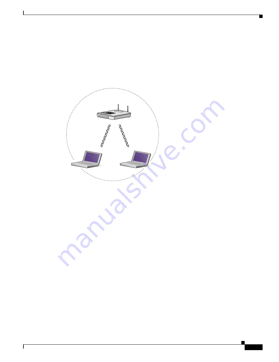
Central Unit in an All-Wireless Network

In an all-wireless network, an access point acts as a stand-alone root unit. The access point is not 
attached to a wired LAN; it functions as a hub linking all stations together. The access point serves as 
the focal point for communications, increasing the communication range of wireless users. 

Figure 1-5


shows an access point in an all-wireless network.

Figure 1-5

Access Point as Central Unit in All-Wireless Network

Access Point

(Root Unit)

65998

Содержание AIR-AP1220B-A-K9 - Aironet 1200 - Wireless Access Point

Страница 1: ...nc 170 West Tasman Drive San Jose CA 95134 1706 USA http www cisco com Tel 408 526 4000 800 553 NETS 6387 Fax 408 526 4100 Cisco Aironet 1200 Series Access Point Hardware Installation Guide Customer Order Number Text Part Number OL 2155 02 ...

Страница 2: ...o antenna until the interference stops Move the equipment to one side or the other of the television or radio Move the equipment farther away from the television or radio Plug the equipment into an outlet that is on a different circuit from the television or radio That is make certain the equipment and the television or radio are on circuits controlled by different circuit breakers or fuses Modifi...

Страница 3: ...hnical Assistance x Cisco com x Technical Assistance Center xi Cisco TAC Web Site xi Cisco TAC Escalation Center xi C H A P T E R 1 Overview 1 1 Key Features 1 2 Dual Band Radio Support 1 2 2 4 GHz Mini PCI Radio Card 1 2 5 GHz Radio Module 1 2 Power 1 3 Antenna Connectors 1 4 2 4 GHz Radio 1 4 Ethernet and Console Ports 1 4 Ethernet Port 1 4 Console Port 1 4 Metal Enclosure 1 4 Indicators 1 5 Sec...

Страница 4: ... Site Surveys 2 6 Unpacking the Access Point 2 6 Package Contents 2 7 Before Beginning the Installation 2 7 Installation Summary 2 8 Connecting the 2 4 GHz Antennas 2 8 Connecting the Ethernet and Power Cables 2 9 C H A P T E R 3 Basic Configuration 3 1 Before You Start 3 2 Summary of Configuration Steps 3 2 Using the IP Setup Utility 3 3 Obtaining and Installing IPSU 3 3 Finding the Access Point ...

Страница 5: ... 4 Removing a 2 4 GHz Radio 5 5 Installing a 2 4 GHz Radio 5 7 C H A P T E R 6 5 GHz Radio Module Upgrade 6 1 Overview 6 2 Unpacking the Radio Module 6 2 Removing the 5 GHz Radio Access Cover 6 2 Removing a 5 GHz Radio Module 6 3 Installing a 5 GHz Radio Module 6 5 C H A P T E R 7 Troubleshooting 7 1 Checking the Top Panel Indicators 7 2 Checking Basic Settings 7 3 SSID 7 3 WEP Keys 7 4 Security S...

Страница 6: ...ay Iceland and Liechtenstein B 4 Declaration of Conformity with Regard to the R TTE Directive 1999 5 EC B 4 Declaration of Conformity for RF Exposure B 6 Guidelines for Operating Cisco Aironet Access Points in Japan B 6 Japanese Translation B 6 English Translation B 7 A P P E N D I X C Console Cable Pinouts C 1 Overview C 2 Console Port Signals and Pinouts C 2 A P P E N D I X D Channels and Antenn...

Страница 7: ...wing sections Chapter 1 Overview describes the features and specifications of access points Chapter 2 Installation provides basic installation instructions Chapter 3 Basic Configuration describes how to enter basic configuration settings Chapter 4 Mounting Instructions provides mounting instructions for the access point Chapter 5 2 4 GHz Radio Upgrade provides instructions for installing upgrading...

Страница 8: ...ations For more information about access points and related products refer to the following publications Quick Start Guide Cisco Aironet 1200 Series Access Point describes how to attach antennas and cables mount the access point and how to obtain access point documentation This document is included in the shipping box with your access point Cisco Aironet 1200 Series Access Point Software Configura...

Страница 9: ... Aironet Wireless LAN Adapters Installation and Configuration Guide for Linux provides hardware features physical and performance characteristics installation instructions for PC card and PCI card client adapters and instructions for installing and using the wireless client adapter utilities running the Linux operating system This document is available on the Cisco CCO web site at the following UR...

Страница 10: ...ts Obtaining Technical Assistance Cisco provides Cisco com as a starting point for all technical assistance Customers and partners can obtain online documentation troubleshooting tips and sample configurations from online tools by using the Cisco Technical Assistance Center TAC Web Site Cisco com registered users have complete access to the technical support resources on the Cisco TAC Web Site Cis...

Страница 11: ...u can use the Cisco TAC Web Site to resolve P3 and P4 issues yourself saving both cost and time The site provides around the clock access to online tools knowledge bases and software To access the Cisco TAC Web Site go to this URL http www cisco com tac All customers partners and resellers who have a valid Cisco service contract have complete access to the technical support resources on the Cisco ...

Страница 12: ...efore calling please check with your network operations center to determine the level of Cisco support services to which your company is entitled for example SMARTnet SMARTnet Onsite or Network Supported Accounts NSA When you call the center please have available your service agreement number and your product serial number ...

Страница 13: ...nt between wireless and wired networks In large installations wireless users within radio range of an access point can roam throughout a facility while maintaining uninterrupted access to the network The access point can support simultaneous dual band 2 4 GHz and 5 GHz radio operation or single band 2 4 GHz only or 5 GHz only radio operation Single band radio units can be field upgraded for dual b...

Страница 14: ...ing a security cable Security hasp to secure the access point to the mounting bracket using a lock Dual Band Radio Support The access point can be initially configured from the factory for single or dual band radio operation However an access point configured for single band radio operation can be field upgraded to support dual band radio operation using the 5 GHz radio module or the 2 4 GHz mini ...

Страница 15: ...s are designed for use with Cisco Aironet 1200 Series Access Points only Using the power injector with other Ethernet ready devices can damage the equipment Caution The 1200 series power injectors are not tested to UL 2043 and should not be placed in a building s environmental air space such as above suspended ceilings Note Only the 1200 series power injector and the 1200 series power module can s...

Страница 16: ...tch with inline power from a power patch panel or from the access point s 1200 series power injector Console Port The console port provides access to the access point s management system using a terminal emulator program Use an RJ 45 to DB 9 serial cable refer to Appendix C Console Cable Pinouts to connect your computer s COM port to the access point s serial console port Assign the following port...

Страница 17: ...nfrastructure The indicator blinks red when the Ethernet cable is not connected The association status indicator signals operational status Blinking green indicates that the access point is operating normally but is not associated with any wireless client devices Steady green indicates that the access point is associated with at least one wireless client device The radio indicator blinks green to ...

Страница 18: ...nstalled on the mounting bracket the holes in the security hasps line up so you can install a padlock Compatible padlocks are Master Lock models 120T or 121T When using the security hasp with a lock the access point is secured to the mounting bracket and the mounting bracket screws along with the 2 4 GHz radio access cover are not accessible The security cable keyhole allows you to secure the acce...

Страница 19: ...ration examples apply to both 2 4 GHz and 5 GHz wireless LANs Root Unit on a Wired LAN An access point connected directly to a wired LAN provides a connection point for wireless users If more than one access point is connected to the LAN users can roam from one area of a facility to another without losing their connection to the network As users move out of range of one access point they automatic...

Страница 20: ...ucture or to overcome an obstacle that blocks radio communication The repeater forwards traffic between wireless users and the wired LAN by sending packets to either another repeater or to an access point connected to the wired LAN The data is sent through the route that provides the greatest performance for the client Figure 1 4 shows an access point acting as a repeater Figure 1 4 Access Point a...

Страница 21: ...ss point acts as a stand alone root unit The access point is not attached to a wired LAN it functions as a hub linking all stations together The access point serves as the focal point for communications increasing the communication range of wireless users Figure 1 5 shows an access point in an all wireless network Figure 1 5 Access Point as Central Unit in All Wireless Network Access Point Root Un...

Страница 22: ... unit Input Current With 2 4 GHz radio 125 mA typical With 5 GHz radio 165 mA typical With 2 4 GHz and 5 GHz radios 225 mA typical The access point is capable of drawing 380 mA depending upon the current radios and future radios installed in the unit Operating Temperature Access point 4 to 131o F 20 to 55o C 1200 series power injector 32 to 104o F 0 to 40o C Access point with 2 4 GHz and 5 GHz rad...

Страница 23: ...ectors are not tested to UL 2043 and should not be placed in a building s environmental air space such as above suspended ceilings Note If you plan to mount the access point in environmental air space using a 5 GHz radio Cisco recommends that you mount the access point horizontally with its antennas pointing down Doing so results in the access point complying with regulatory requirements for envir...

Страница 24: ...ns EMI and Susceptibility FCC Part 15 107 and 15 109 Class B ICES 003 Class B Canada EN 55022 B AS NZS 3548 Class B VCCI Class B EN 55024 EN 301 489 1 EN 301 489 17 RF Exposure OET 65C RSS 102 ANSI C95 1 Table 1 1 Access Point Specifications continued Category Access Point with 2 4 GHz Radio Access Point with 5 GHz Radio Module ...

Страница 25: ...setup of the access point and includes the following sections Safety Information page 2 2 Warnings page 2 3 Installation Guidelines page 2 4 Unpacking the Access Point page 2 6 Before Beginning the Installation page 2 7 Installation Summary page 2 8 Connecting the 2 4 GHz Antennas page 2 8 Connecting the Ethernet and Power Cables page 2 9 ...

Страница 26: ... not touch or move the antenna while the unit is transmitting or receiving Do not hold any component containing a radio such that the antenna is very close to or touching any exposed parts of the body especially the face or eyes while transmitting Do not operate the radio or attempt to transmit data unless the antenna is connected otherwise the radio may be damaged Use in specific environments The...

Страница 27: ...electric light or power circuits or where it can come into contact with such circuits When installing the antenna take extreme care not to come into contact with such circuits as they may cause serious injury or death For proper installation and grounding of the antenna please refer to national and local codes e g U S NFPA 70 National Electrical Code Article 810 in Canada Canadian Electrical Code ...

Страница 28: ...m microwave ovens Microwave ovens operate on the same frequency as the access point and can cause signal interference Installation Above Suspended Ceilings The access point uses a metal enclosure having adequate fire resistance and low smoke producing characteristics suitable for operation in a building s environmental air space in accordance with Section 300 22 c of the NEC such as above suspende...

Страница 29: ...gure 2 1 The total bandwidth available to each wireless client device depends on the amount of data each mobile station needs to transfer and the number of stations located in each cell Seamless roaming is supported as a client device moves in and out of range of each access point thereby maintaining a constant connection to the wired LAN Each device in the radio network must be configured with th...

Страница 30: ...frequencies Data rates Sensitivity and range are inversely proportional to data bit rates The maximum radio range is achieved at the lowest workable data rate A decrease in receiver threshold sensitivity occurs as the radio data increases Antenna type and placement Proper antenna configuration is a critical factor in maximizing radio range As a general rule range increases in proportion to antenna...

Страница 31: ...o documentation feedback cards Before Beginning the Installation Before you begin the installation process please refer to Figure 2 2 and Figure 2 3 to become familiar with the access point s layout connectors and 5 GHz module location Figure 2 2 Access Point Layout and Connectors Figure 2 3 5 GHz Radio Module 1 2 4 GHz antenna connectors 5 Mode button possible future feature 2 48 VDC power port 6...

Страница 32: ...isco Aironet 1200 Series Access Point Software Configuration Guide Connecting the 2 4 GHz Antennas The access point supports a single antenna or dual diversity antennas Two R TNC antenna connectors are provided on the back of the unit for the 2 4 GHz radio If you are using a Cisco Aironet 2 dBi antenna follow the steps below Step 1 Attach an antenna to the Right Primary 2 4 GHz R TNC antenna conne...

Страница 33: ...eries power module can support operation of the 5 0 GHz radio in the access point Note If you use in line power from a switch or patch panel do not connect the 1200 series power module to the access point Using two power sources on the access point might cause the switch or patch panel to shut down the port to which the access point is connected Power cord Universal power supply SYST RPS DUPLX MOD...

Страница 34: ...hernet cable from the access point into the end of the 1200 series power injector labeled To AP Bridge b Connect an Ethernet cable from the end of the 1200 series power injector labeled To Network to the your 10 100 Ethernet LAN c Plug the female end of the AC power cord into the 1200 series power module Universal power supply and plug the male end into a suitable AC power receptacle Step 3 If you...

Страница 35: ...m and the serial interface You can also reach the management system through a Telnet session Consult the Cisco Aironet 1200 Series Access Point Software Configuration Guide for complete instructions on using these interfaces This chapter includes the following sections Before You Start page 3 2 Summary of Configuration Steps page 3 2 Using the IP Setup Utility page 3 3 Entering Basic Settings page...

Страница 36: ...er access point features refer to the Cisco Aironet 1200 Series Access Point Software Configuration Guide You will follow these general steps to enter the access point s basic settings 1 Connect the Ethernet and power cables to the access point For instructions refer to the Connecting the Ethernet and Power Cables section on page 2 8 2 Use an Internet browser to open the access point s management ...

Страница 37: ... IPSU Step 1 Use your Internet browser to access the Cisco Software Center at the following URL http www cisco com public sw center sw wireless shtml Step 2 Locate the utilities section and click on the individual files link for Windows Step 3 Click IPSUvxxxxx exe The vxxxxxx identifies the software package version number Step 4 Read and accept the terms and conditions of the Software License Agre...

Страница 38: ... field write it down If IPSU reports that the IP address is 10 0 0 1 the default IP address then the access point did not receive a DHCP assigned IP address To change the access point IP address using IPSU refer to the Setting the Access Point IP Address and SSID section on page 3 4 To change the access point IP address using the console port refer to the Assigning Basic Settings section on page 3...

Страница 39: ...en Step 3 Enter the access point s MAC address in the Device MAC ID field The access point s MAC address is printed on the label on the bottom of the unit It should contain six pairs of hexadecimal digits Your access point s MAC address might look like the following example 004096xxxxxx Note The MAC address field is not case sensitive Step 4 Enter the IP address you want to assign to the access po...

Страница 40: ... is labeled Netsite or Location if you are using Microsoft Internet Explorer the field is labeled Address Press Enter Step 2 When the access point s Summary Status page appears click Setup When the Setup page appears click Express Setup The Express Setup screen appears Figure 3 3 Note If the access point is new and its factory configuration has not been changed the Express Setup screen appears ins...

Страница 41: ...abled this field is the subnet mask If DHCP or BOOTP is enabled this field provides the subnet mask only when no server responds to the access point s DHCP or BOOTP request Step 7 Enter the IP address of your default internet gateway in the Default Gateway field The entry 255 255 255 255 indicates no gateway Clicking the Gateway link takes you to the Routing Setup page which you use to configure t...

Страница 42: ... from the Role in Radio Network drop down arrow The menu contains the following options Root Access Point A wireless LAN transceiver that connects an Ethernet network with wireless client stations Use this setting if the access point will be connected to the wired LAN Repeater Access Point An access point that transfers data between a client and another access point Use this setting for access poi...

Страница 43: ...ges and Settings With the serial interface when you enter names and settings that appear in brackets you jump to that page or setting HyperTerminal jumps to the page or setting as soon as it recognizes a unique name so you need to enter only the first few characters in the page or setting name For example to jump from the home page to the Setup page you only need to type s Applying Changes to the ...

Страница 44: ...pe s and the Setup screen appears b Type ex and the Express Setup screen appears c Go to Step 5 Step 5 Type na to select System Name Enter a system name for the access point and press Enter A descriptive system name makes it easy to identify the access point on your network Step 6 Type t and then press Enter to select Terminal Type To specify the type of console interface perform one of the follow...

Страница 45: ...at client devices use to associate with the access point The SSID can be any alphanumeric entry from 2 to 32 characters b Type ro and then press Enter to select Role in Radio Network The network roles include the following options Root Access Point Type ro and then press Enter to select this setting A wireless LAN transceiver that connects an Ethernet network with wireless client stations Use this...

Страница 46: ...e this setting for access points not connected to the wired LAN Site Survey Client Type s and then press Enter to select this setting A station with a wireless connection to an access point Use this setting for diagnostics such as when you need to test the access point by having it communicate with another access point c Type op and then press Enter to select Optimize Radio Network For These optio...

Страница 47: ... AP1200 xxxxxx the last six characters of the unit s MAC address Terminal Type on serial interface only teletype Config Server Protocol DHCP IP address 10 0 0 1 IP Subnet Mask 255 255 255 0 Default Gateway 255 255 255 255 AP Radio Internal 2 4 GHz radio SSID tsunami Role in Radio Network Root Access Point Optimize Radio Network For Throughput AP Radio Module 5 GHz radio SSID tsunami Role in Radio ...

Страница 48: ...3 14 Cisco Aironet 1200 Series Access Point Hardware Installation Guide OL 2155 02 Chapter 3 Basic Configuration Default Basic Settings ...

Страница 49: ...to suspended ceilings vertical surfaces or horizontal surfaces using the access point mounting bracket The following sections are included in this chapter Overview page 4 2 Mounting on a Horizontal or Vertical Surface page 4 3 Mounting on a Suspended Ceiling page 4 4 Attaching the Access Point to the Mounting Bracket page 4 5 Securing the Access Point to the Mounting Bracket page 4 5 ...

Страница 50: ...esistance and low smoke producing characteristics suitable for operation in a building s environmental air space in accordance with Section 300 22 C of the National Electrical Code NEC such as above suspended ceilings Note If you plan to mount the access point with the 5 GHz radio in environmental air space Cisco recommends that you mount the access point horizontally with its antennas pointing do...

Страница 51: ...you are using wall anchors 1 8 in 6 3 mm if you are not using wall anchors Step 3 Install the anchors into the wall if you are using them Otherwise go to Step 4 Step 4 Secure the mounting bracket to the surface using the 8 fasteners Note On a vertical surface mount the bracket with its security hasp facing down Step 5 Attach the access point to the mounting bracket Note You can make your installat...

Страница 52: ...on a Suspended Ceiling Note To comply with NEC code a 10 24 grounding lug is provided on the mounting bracket You should review Figure 4 2 before beginning the mounting process Figure 4 2 Mounting Bracket Parts 1 2 2 3 5 3 4 5 74121 1 Suspended ceiling T rail 4 Mounting bracket 2 Caddy fastener 5 Keps nut contains an attached lock washer 3 Plastic spacer ...

Страница 53: ...ing Bracket Follow these steps to attach the access point to the mounting bracket Step 1 Line up the three mounting pins on the access point with the large ends of the keyhole shaped holes on the mounting bracket Step 2 Insert the access point into the keyhole shaped holes and maintain a slight pressure to hold it in place Step 3 Slide the access point s mounting pins into the small ends of the ke...

Страница 54: ...4 6 Cisco Aironet 1200 Series Access Point Hardware Installation Guide OL 2155 02 Chapter 4 Mounting Instructions Securing the Access Point to the Mounting Bracket ...

Страница 55: ...dware Installation Guide OL 2155 02 5 2 4 GHz Radio Upgrade This section contains the following topics Overview page 5 2 Opening the Access Cover page 5 3 Removing a Blank Spacer Card page 5 4 Removing a 2 4 GHz Radio page 5 5 Installing a 2 4 GHz Radio page 5 7 ...

Страница 56: ...Hz radio feature remove the blank spacer card For an access point with the 2 4 GHz radio feature remove the existing 2 4 GHz card Install the new 2 4 GHz radio card Close the access point 2 4 GHz radio access cover Caution ESD can damage the Cisco Aironet radio and the internal components of the access point It is recommended that the 2 4 GHz radio upgrade procedures be performed by an ESD trained...

Страница 57: ...ace Step 4 Discharge any static buildup on your body by touching a grounded surface antistatic work surface before proceeding Step 5 Position the access point so that the bottom cover is facing up Caution The internal access point components and the 2 4 GHz radio can be damaged by ESD from improper handling Step 6 Remove the bottom access cover see Figure 5 1 using the T 10 tamper resistant Torx L...

Страница 58: ... and observe all ESD precautions The internal access point components and the 2 4 GHz radio can be damaged by ESD from improper handling To remove the blank spacer card from the mini PCI connector following the steps below Step 1 Push the card retaining clips on each side of card away from the card see Figure 5 2 When released the board springs up Figure 5 2 Location of Retaining Clips on Blank Sp...

Страница 59: ...lling the radio card go to the Installing a 2 4 GHz Radio section Removing a 2 4 GHz Radio To remove a 2 4 GHz radio card from your access point follow the steps below Caution The internal access point components and the 2 4 GHz radio can be damaged by ESD from improper handling Step 1 Use your fingers to carefully remove the antenna wire connectors from the 2 4 GHz radio card Caution The antenna ...

Страница 60: ... card see Figure 5 3 When released the radio card springs up see Figure 5 4 Figure 5 3 Location of Retaining Clips on 2 4 GHz Radio Card b Grasp the radio card only on the edges being careful not to touch components on the board or the gold connector pins c Remove the 2 4 GHz card from the mini PCI connector Step 3 Place the removed 2 4GHz radio card into an anti static bag For instructions on ins...

Страница 61: ...i static bag Step 2 Grasp the radio card only on the edges being careful not to touch components on the board or the gold connector pins Step 3 Connect the black antenna wire connector to the radio card antenna connector marked by the black label see Figure 5 4 Caution To avoid damaging the antenna wire assemblies handle them by their connectors Figure 5 4 Antenna Connector Labels and Mini PCI Con...

Страница 62: ... antenna connectors are touching when power is applied If they are touching carefully rotate them in opposite directions until they are separated Step 8 Reinstall the 2 4 GHz radio access cover and use the T 10 tamper resistant Torx L wrench to tighten the cover s retaining screw Step 9 Remove the backing paper from the 2 4 GHz radio product compliance label Step 10 Carefully attach the label in t...

Страница 63: ... 2155 02 6 5 GHz Radio Module Upgrade This chapter provides upgrade instructions for the 5 GHz radio module and includes the following sections Overview page 6 2 Removing the 5 GHz Radio Access Cover page 6 2 Removing a 5 GHz Radio Module page 6 3 Installing a 5 GHz Radio Module page 6 5 ...

Страница 64: ...ccess point with the 5 GHz radio feature remove the existing 5 GHz radio module 5 Install the new 5 GHz radio module Unpacking the Radio Module Each 5 GHz radio module is shipped with the following items Quick start guide A product registration card A T 10 tamper resistant Torx L wrench A 5 GHz radio product compliance label If anything is missing or damaged contact your Cisco representative for s...

Страница 65: ...the instructions below Step 1 Remove all cables and power connections from the access point Step 2 Place the access point on a flat surface so that the unit is upright with the front end facing you Step 3 Unscrew the two mounting screws using the supplied Torx L wrench Figure 6 2 Figure 6 2 5 GHz Radio Module Note Do not attempt to remove the mounting screws from the module they are captured in th...

Страница 66: ...5 GHz Radio Module Step 4 Insert your fingers into the base of the 5 GHz radio module closest to the access point and pull straight out from the access point see Figure 6 3 Figure 6 3 Removing the 5 GHz Radio Module Step 5 Fold the antenna down towards the attached radio card and insert the module into a static protected bag 74629 ...

Страница 67: ...io module refer to Removing the 5 GHz Radio Access Cover or Removing a 5 GHz Radio Module Step 2 Place the access point on a flat surface so that the unit is upright with the front end facing you Step 3 Grasp the new 5 GHz radio module by it s base with the antenna pointing up and insert the card into the access point s card bus slot see Figure 6 4 Figure 6 4 Installing a 5 GHz Radio Module Step 4...

Страница 68: ...ied Torx L wrench Figure 6 5 Location of Mounting Screws Step 6 Remove the backing paper from the 5 GHz radio product compliance label Step 7 Carefully attach the label in the space provided below the product compliance label see Figure 6 6 Figure 6 6 5 GHz Radio Product Compliance Label 1 5 GHz radio module antenna 2 Mounting screws 2 2 1 74630 1 5 GHz radio product compliance label 2 Access poin...

Страница 69: ...access point contains an internal 2 4 GHz radio there will also be a 2 4 GHz radio product compliance label on the back of the unit The 5 GHz radio module installation is now complete To configure the 5 GHz radio with your wireless network settings refer to Chapter 3 Basic Configuration and to the Cisco Aironet 1200 Series Access Point Software Configuration Guide ...

Страница 70: ...6 8 Cisco Aironet 1200 Series Access Point Hardware Installation Guide OL 2155 02 Chapter 6 5 GHz Radio Module Upgrade Installing a 5 GHz Radio Module ...

Страница 71: ...eshooting information refer to the Cisco Aironet 1200 Series Access Point Software Configuration Guide For the most up to date troubleshooting information refer to the Cisco TAC website at the following URL select Top Issues and then select Wireless Technologies http www cisco com tac Sections in this chapter include Checking the Top Panel Indicators page 7 2 Checking Basic Settings page 7 3 Reset...

Страница 72: ... green indicates that the access point is operating normally but is not associated with any wireless devices Steady green indicates that the access point is associated with a wireless client For repeater access points blinking 50 on 50 off indicates the repeater is not associated with the root access point blinking 7 8 on 1 8 off indicates that the repeater is associated with the root access point...

Страница 73: ...t different SSIDs for the 2 4 GHz and 5 GHz radios Message type Ethernet indicator Status indicator Radio indicator Meaning Association status Steady green At least one wireless client device is associated with the unit Blinking green No client devices are associated check the unit s SSID and WEP settings Operational Steady green Blinking green Transmitting receiving radio packets Blinking green S...

Страница 74: ...s in the client adapter and for the wireless client adapter driver and firmware versions that are compatible with the access point settings Refer to the Cisco Aironet 1200 Series Access Point Software Configuration Guide for instructions on setting and verifying the access point s security options Resetting to the Default Configuration If you forget the password that allows you to configure the ac...

Страница 75: ...arity No parity Stop bits 1 Flow control Xon Xoff or None Step 6 Click OK and press Enter Step 7 When the Summary Status screen appears reboot the access point by unplugging the power connector or the Ethernet cable when using in line power and then plugging it back in Step 8 When the access point reboots and the Summary Status screen reappears type resetall and press Enter Step 9 Type yes and pre...

Страница 76: ...7 6 Cisco Aironet 1200 Series Access Point Hardware Installation Guide OL 2155 02 Chapter 7 Troubleshooting Resetting to the Default Configuration ...

Страница 77: ...ear in this publication These translated warnings apply to other documents in which they appear in English The following safety warnings appear in this appendix Dipole Antenna Installation Warning page A 2 Explosive Device Proximity Warning page A 3 Installation and Grounding Warning page A 4 Lightning Activity Warning page A 6 Installation Warning page A 7 Circuit Breaker 15A Warning page A 8 ...

Страница 78: ...ersonne Warnung Um die in den FCC Richtlinien festgelegten Expositionshöchstgrenzen für Radiofrequenzen RF nicht zu überschreiten sollten Dipolantennen mindestens 20 cm 7 9 Zoll vom Körper aller Person entfernt aufgestellt werden Avvertenza Per conformarsi ai limiti FCC di esposizione a radiofrequenza RF le antenne a dipolo devono stare ad una distanza minima di 20 cm dal corpo di ogni persona Adv...

Страница 79: ... modifié à cet effet Warnung Benutzen Sie Ihr drahtloses Netzwerkgerät nicht in der Nähe ungeschützter Sprengkapseln oder anderer explosiver Stoffe es sei denn Ihr Gerät wurde eigens für diesen Gebrauch modifiziert und bestimmt Avvertenza Non utilizzare la periferica di rete senza fili in prossimità di un detonatore non protetto o di esplosivi a meno che la periferica non sia stata modificata a ta...

Страница 80: ...asennus ja maadoitustiedot kansallisista ja paikallisista sähkösäännöksistä esimerkiksi Yhdysvalloissa NFPA 70 National Electrical Code Article 810 ja Kanadassa Canadian Electrical Code Section 54 Attention Ne placez pas l antenne à proximité d une ligne aérienne ou d autres circuits d éclairage ou d alimentation ou dans un endroit où elle risque d être en contact avec des circuits de ce type Lors...

Страница 81: ...nte a antena consulte a legislação local e nacional por ex NFPA 70 National Electrical Code Artigo 810 Canadá Canadian Electrical Code Seção 54 Advertencia No coloque la antena cerca de cables de tendido eléctrico u otros circuitos ni donde pueda entrar en contacto con dichos circuitos Al instalar la antena extreme las precauciones para no entrar en contacto con circuitos de esas características y...

Страница 82: ...travailler sur le système ni brancher ou débrancher les câbles pendant un orage Warnung Arbeiten Sie nicht am System und schließen Sie keine Kabel an bzw trennen Sie keine ab wenn es gewittert Avvertenza Non lavorare sul sistema o collegare oppure scollegare i cavi durante un temporale con fulmini Advarsel Utfør aldri arbeid på systemet eller koble kabler til eller fra systemet når det tordner ell...

Страница 83: ...ancher le système sur la source d alimentation consulter les directives d installation Warnung Lesen Sie die Installationsanweisungen bevor Sie das System an die Stromquelle anschließen Avvertenza Consultare le istruzioni di installazione prima di collegare il sistema all alimentatore Advarsel Les installasjonsinstruksjonene før systemet kobles til strømkilden Aviso Leia as instruções de instalaçã...

Страница 84: ...Sie sicher daß eine Sicherung oder ein Unterbrecher von nicht mehr als 240 V Wechselstrom 10 A bzw in den USA 120 V Wechselstrom 15 A an den Phasenleitern allen stromführenden Leitern verwendet wird Avvertenza Questo prodotto dipende dall installazione dell edificio per quanto riguarda la protezione contro cortocircuiti sovracorrente Verificare che un fusibile o interruttore automatico non superio...

Страница 85: ...nd regulatory information for the Cisco Aironet 1200 Series Access Points This appendix contains the following sections Manufacturers Federal Communication Commission Declaration of Conformity Statement Department of Communications Canada European Community Switzerland Norway Iceland and Liechtenstein Declaration of Conformity for RF Exposure Guidelines for Operating Cisco Aironet Access Points in...

Страница 86: ...vironment This equipment generates uses and radiates radio frequency energy and if not installed and used in accordance with the instructions may cause harmful interference However there is no guarantee that interference will not occur If this equipment does cause interference to radio or television reception which can be determined by turning the equipment off and on the user is encouraged to cor...

Страница 87: ...at may cause undesired operation Cisco Aironet 11 Mbps 2 4 GHz Access Points are certified to the requirements of RSS 139 1 and RSS 210 for 2 4 GHz spread spectrum devices and Cisco Aironet 54 Mbps 5 GHz Access Points are certified to the requirements of RSS 210 for 5 GHz spread spectrum devices The use of this device in a system operating either partially or completely outdoors may require the us...

Страница 88: ...C Έλληνας Αυτός ο εξοπλισµός συµµορφώνεται µε τις ουσιώδεις απαιτήσεις και τις λοιπές διατάξεις της Οδηγίας 1999 5 EΚ Français Cet appareil est conforme aux exigencies essentialles et aux autres dispositions pertinantes de la Directive 1999 5 EC Íslenska Þessi búnaður samrýmist lögboðnum kröfum og öðrum ákvæðum tilskipunar 1999 5 ESB Italiano Questo apparato é conforme ai requisiti essenziali ed a...

Страница 89: ...tain frequencies and or may require a license for operation For more details contact Cisco Corporate Compliance Note Combinations of power levels and antennas resulting in a radiated power level above 100 mW equivalent isotropic radiated power EIRP are considered as not compliant with the above mentioned directive and are not allowed for use within the European community and other countries that h...

Страница 90: ...n 20 cm from your body or nearby persons The access point with 5 GHz integrated antenna must be installed to maintain a minimum 20 cm 7 9 in co located separation distance from other FCC approved indoor outdoor antennas used with the access point Any antennas or transmitters not approved by the FCC cannot be co located with the access point antennas The access point s co located 2 4 GHz 2 2 dBi an...

Страница 91: ... stations and unlicensed specified low power radio stations used in factory production lines 1 Before using this equipment make sure that no premises radio stations or specified low power radio stations of RF ID are used in the vicinity 2 If this equipment causes RF interference to a premises radio station of RF ID promptly change the frequency or stop using the device contact the number below and...

Страница 92: ... Cisco Aironet 1200 Series Access Point Hardware Installation Guide OL 2155 02 Appendix B Declarations of Conformity and Regulatory Information Guidelines for Operating Cisco Aironet Access Points in Japan ...

Страница 93: ... 2155 02 A P P E N D I X C Console Cable Pinouts This appendix identifies the pinouts for the serial console cable that connects to the access point s serial console port The appendix contains the following sections Overview page C 2 Console Port Signals and Pinouts page C 2 ...

Страница 94: ... the console RJ 45 to DB 9 serial cable to connect the access point s console port to the COM port of your PC running a terminal emulation program Note Both the Ethernet and console ports use RJ 45 connectors Be careful to avoid accidently connecting the serial cable to the Ethernet port connector Table C 1 lists the signals and pinouts for the console RJ 45 to DB 9 serial cable 1 NC indicates not...

Страница 95: ...annels and Antenna Settings This appendix lists the IEEE 802 11a 5 GHz and IEEE 802 11b 2 4 GHz channels maximum power levels and antenna gains supported by the world s regulatory domains The following topics are covered in this appendix Channels page D 2 Maximum Power Levels and Antenna Gains page D 4 ...

Страница 96: ... with the regulatory standards of Mexico Note France is included in the EMEA E regulatory domain however channels 1 through 9 can be used with up to 10 mW EIRP and channels 10 through 13 can be used with up to 100 mW EIRP Users are responsible for ensuring that the channel set configuration is in compliance with the regulatory standards of France Table D 1 Channels for IEEE 802 11b Channel Identif...

Страница 97: ...h 20 MHz wide channel are shown in Table D 2 All channel sets are restricted to indoor usage except the Americas A allows for indoor and outdoor use on channels 52 64 Table D 2 Channels for IEEE 802 11a Channel Identifier Center Frequency MHz Regulatory Domains Americas A Japan J Singapore S Taiwan T 34 5170 X 36 5180 X X 38 5190 X 40 5200 X X 42 5210 X 44 5220 X X 46 5230 X 48 5240 X X 52 5260 X ...

Страница 98: ... power EIRP above the amount allowed per regulatory domain Table D 3 indicates the maximum power levels and antenna gains allowed for each regulatory domain Table D 3 Maximum Power Levels Per Antenna Gain for IEEE 801 11b Regulatory Domain Antenna Gain dBi Maximum Power Level mW Americas A 4 watts EIRP maximum 0 100 2 2 100 5 2 100 6 100 8 5 100 12 100 13 5 100 21 20 EMEA E 100 mW EIRP maximum 0 1...

Страница 99: ...and channels 10 through 13 can be used with up to 100 mW EIRP Users are responsible for ensuring that the channel set configuration is in compliance with the regulatory standards of France Israel I 100 mW EIRP maximum 0 100 2 2 50 5 2 30 6 30 8 5 5 12 5 13 5 5 21 1 China C 10 mW EIRP maximum 0 5 2 2 5 5 2 n a 6 n a 8 5 n a 12 n a 13 5 n a 21 n a Table D 3 Maximum Power Levels Per Antenna Gain for ...

Страница 100: ...ower EIRP above the amount allowed per regulatory domain Table D 4 indicates the maximum power levels allowed with the Cisco integrated antenna for each regulatory domain Table D 4 Maximum Power Levels Per Antenna Gain for IEEE 802 11a Regulatory Domain Maximum Power Level mW with 6 dBi Antenna Gain Americas A 160mW EIRP Maximum on channels 36 48 800mW EIRP maximum on channels 52 64 40 Japan J 10 ...

Страница 101: ...reless stations Ad Hoc Network A wireless network composed of stations without Access Points Antenna Gain The gain of an antenna is a measure of the antenna s ability to direct or focus radio energy over a region of space High gain antennas have a more focused radiation pattern in a specific direction Associated A station is configured properly to allow it to wirelessly communicate with an Access ...

Страница 102: ...na that is commonly used to measure antenna gain The greater the dBi value the higher the gain and the more acute the angle of coverage DHCP Dynamic host configuration protocol A protocol available with many operating systems that automatically issues IP addresses within a specified range to devices on the network The device retains the assigned address for a specific administrator defined period ...

Страница 103: ...Gateway A device that connects two otherwise incompatible networks together GHz Gigahertz One billion cycles per second A unit of measure for frequency I IEEE Institute of Electrical and Electronic Engineers A professional society serving electrical engineers through its publications conferences and standards development activities The body responsible for the Ethernet 802 3 and wireless LAN 802 1...

Страница 104: ...o a primarily circular antenna radiation pattern Orthogonal Frequency Division Multiplex OFDM A modulation technique used by IEEE 802 11a compliant wireless LANs for transmission at 6 9 12 18 24 36 48 and 54 Mbps P Packet A basic message unit for communication across a network A packet usually includes routing information data and sometimes error detection information Q Quadruple Phase Shift Keyin...

Страница 105: ...ervice Set Identifier also referred to as Radio Network Name A unique identifier used to identify a radio network and which stations must use to be able to communicate with each other or to an access point The SSID can be any alphanumeric entry up to a maximum of 32 characters T Transmit Power The power level of radio transmission U UNII Unlicensed National Information Infrastructure regulations f...

Страница 106: ...Glossary GL 6 Cisco Aironet 1200 Series Access Point Hardware Installation Guide OL 2155 02 ...

Страница 107: ...2 10 connectors 1 4 1 10 1 11 3 9 console port 1 4 3 9 C 2 conventions document viii coverage minimal overlap 2 5 D data rates 1 11 2 6 declarations of conformity B 1 default configuration resetting 7 4 gateway 3 7 3 11 settings 3 13 DHCP 3 2 3 7 3 10 documentation conventions viii related publications viii E EIRP maximum D 4 D 6 ensure compatibility setting 3 8 3 12 environmental air space 1 4 en...

Страница 108: ...re 1 10 optimize radio network 3 8 3 11 3 12 P package contents 2 7 password reset 7 4 pinouts serial cable C 2 ports Ethernet and serial 1 4 power connecting 2 9 injector 2 9 inline 1 3 input 1 10 output 1 10 power injector 1 3 power level maximum D 4 R radio indicator 7 2 range 1 11 3 8 3 11 3 12 regulatory B 1 domains D 2 D 3 related publications viii repeater non root 3 7 3 8 3 11 3 12 repeate...

Страница 109: ...an Internet browser 3 7 3 8 using the console port 3 11 3 12 status indicators 1 10 7 2 storage temperature 1 10 subnet mask 3 7 3 11 system name 3 13 T TAC 7 1 temperature operating 1 10 storage 1 10 terminal emulator 3 2 3 9 terminal type 3 13 throughput 3 8 3 11 3 12 troubleshooting 7 1 U Unlicensed National Information Infrastructure UNII 1 2 unpacking 2 6 V voltage range 1 10 W warnings viii ...

Страница 110: ...Index IN 4 Cisco Aironet 1200 Series Access Point Hardware Installation Guide OL 2155 02 ...

Отзывы: