


Appendix C Technical Specifications
Cable Specifications
C-2
Cisco Unified IP Phone 7931G Administration Guide for Cisco Unified Communications Manager 6.0
OL-12457-01
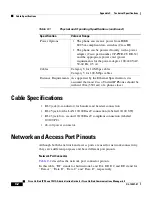
Cable Specifications
•
RJ-9 jack (4-conductor) for handset and headset connection.
•
RJ-45 jack for the LAN 10/100BaseT connection (labeled 10/100 SW).
•
RJ-45 jack for a second 10/100BaseT compliant connection (labeled
10/100 PC).
•
48-volt power connector.
Network and Access Port Pinouts
Although both the network and access ports are used for network connectivity,
they serve different purposes and have different port pinouts.
Network Port Connector
Table C-2
describes the network port connector pinouts.
In this table, “BI” stands for bidirectional, and DA, DB, DC and DD stand for
“Data A”, “Data B”, “Data C” and “Data D”, respectively.
Power Options
•
The phone can receive power from IEEE
802.3af-compliant data switches (Class III)
•
The phone can be powered locally with a power
adapter (Cisco part number CP-PWR-CUBE-3=)
and the appropriate power cord (power
requirements for the power adapter: 100-240 VAC,
50-60 Hz, 0.5 A)
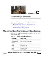
Cables
Category 3 for 10-Mbps cables
Category 5 for 100-Mbps cables
Distance Requirements As supported by the Ethernet Specification, it is
assumed that most Cisco Unified IP Phones should be
within 100m (330 feet) of a phone closet
Table C-1
Physical and Operating Specifications (continued)
Specification
Value or Range


