


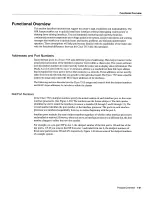


Physical
Description
six-pin
mini-DIN
connector
on
the
multimode/multimode
and
single-mode/single-mode
FIPs
provides
the connection
for an
optical bypass
switch
When
the interface
is
shut
down
the bypass
switch
allows
the
light
signal
to
pass
directly
from
the receive port
to
the transmit
port
on
the bypass
switch
completely
bypassing
the
PIP
transceivers
The
bypass
switch
does
not repeat the signal
and
significant
signal
loss
may
occur
when
transmitting
to
stations
at
maximum
distances
Optical
bypass
switches
typically
use
six-pin
DIN
or
mini-DIN
connector
DIN-to-mini-DIN
adapter
cable
CAB
-FMDD
is
included
with
the
PIP
to
allow
connection
to
either
type of connector
For
detailed
description
of
optical
bypass
and
PDDI
connections
refer
to
the section
FDDI
Connection
Equipment
in
the chapter
Preparing
for Installation
For
descriptions
of
FDDI
network
connections
refer
to
the section
FDDI
Connections
in the chapter
Installing
the
Router
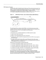
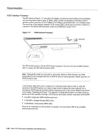
Fast
Serial
Interface
Processor
The
FSIP
provides
four
or eight channel-independent
synchronous
serial
ports
that
support
full
duplex
operation
at
Ti
1.544
Mbps
and El 2.048
Mbps
speeds Each
port
supports
any
of the
available
interface
types EIAITIA-232
EIAITIA-449
V.35
X.21 EIA-530
and E1-G.703/G.704
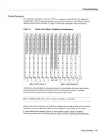
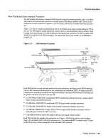
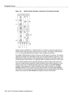
Figure
1-14
shows
an
eight-port
FSIP
The
eight
ports
are divided
into
two
four-port
modules
each
of
which
is
controlled
by
dedicated
Motorola
MC68
040
processor
and
contains
128
kilobytes
KB
of
static
random-access
memory
SRAM
Each
module
can
support
up
to
Ti
or
El
interfaces
and
an
aggregate
bandwidth
of
up
to
Mbps
at
full-duplex
operation
The
type
of
electrical
interface
the
amount
of
traffic
and
the types of external data service
units
DSUs
connected
to
the
ports
affect
actual
rates
For
information
on
setting
up
high-speed
interfaces
refer
to
the section
Configuring
the
FSIP
in
the chapter
Maintaining
the
Router
The
default
FSIP microcode
resides
on
PLCC-type
EPROM
in socket
U8
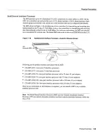
Figure
1-14
Fast
Serial Interface
Processor
Port
Additional
port
adapters
are available
as
spares
so
that
you
can
replace
one
that
fails
however
you
cannot
upgrade
afour-port
FSIP
to
an
eight-port by adding
port
adapters Each
FSIP
comprises
an
FSIP board
with
two
or four
port
adapters
installed
Following
are the
FSIP
product
numbers
CX-FSIP4
CX-FSIP8
four-
and
eight-port interface
processors
PA-7KF-El/75
PA-7KF-El/120
two-port
75-
and 120-ohm
Ei-G.703/G.704
port
adapters
PA-7KF-SPA
two-port
universal
serial
port
adapter
The
four-port
FSIP
is
not constructed
to
support additional
ports
after
it
leaves
the factory
It
contains
the
circuitry
to
control
only
one
four-port
module
For
port adapter
descriptions
refer
to
Universal
Serial
Port
Adapters
which
follows
in
this
section
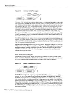
ROM
Translation
of
DCE LED
states
for
DCE
ports
RxC
TxC
RxD
TxD
TxC
RxC
CONN
CONN
1-24
Cisco
7513
Hardware
Installation
and
Maintenance
Содержание 7513 Series
Страница 1: ......
Страница 11: ...Cisco 7513 Hardware Installation and Maintenance ...
Страница 121: ...Site Log 2 56 Cisco 7513 Hardware Installation and Maintenance ...
Страница 162: ...Troubleshooting the Processor Subsystem 4 10 Cisco 7513 Hardware Installation and Maintenance ...
Страница 266: ...Interface Processor LEDs B 16 Cisco 7513 Hardware Installation and Maintenance ...
Страница 270: ...C 4 Cisco 7513 Hardware Installation and Maintenance ...
Страница 288: ...18 Cisco 7513 Hardware Installation and Maintenance ...


