


Physical
Description
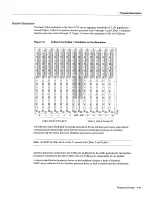
The
front
and back
of the chassis
must
remain
unobstructed
to
ensure
adequate
airflow
and
prevent
overheating
inside
the chassis
we
recommend
at least
six
inches
of clearance
See
the section
Site
Requirements
in
the chapter
Preparing
for
Installation
speed
control
board
in the
blower module
monitors
and
controls
the operation
of the
variable-speed
blower The
variable-speed
feature
enables
quieter operation
by
allowing
the
blower
to
operate
at less
than
maximum
speed
when
doing
so provides
adequate
cooling
air
to
maintain
an
acceptable
operating
temperature
inside
the chassis
The
variable-speed
feature
also provides
for
longer
blower
bearing
life
The
blower
speed
control
can
be
overridden
to
always
run the
blower
at
maximum
speed
Temperature
sensors
on
the chassis interface
and
RSP2
monitor
the
internal
air
temperature
When
the
ambient
air
temperature
is
within
the
normal
operating
range
the
blower
operates
at
the slowest
speed
which
is
55
percent
of the
maximum
speed
If
the temperature
inside
the chassis exceeds
the
normal range
the
blower
speed
control
board
increases
the
blower
speed
to
provide
additional
cooling
air
to
the
internal
components
If the
temperature
continues
to
rise the
blower
speed
control
board
linearly
increases
the
blower
speed
until
the
blower
reaches
full
speed
100
percent
If
the
internal temperature
exceeds
the specified threshold
the system
environmental
monitor
shuts
down
all
internal
power
to
prevent
equipment
damage
from
excessive
heat
If
the
system
detects
that
the
blower
has
stopped
or cannot
maintain
sufficient
blower speed
it
will
display
warning message
on
the console
screen
If
the condition
is
not corrected
the system
might
shut
down
the processor
modules
to
avoid
an
overtemperature
condition
and
potential system
damage
For
specific
thresholds
and
message
descriptions
refer
to
the
section
Environmental
Monitoring
and
Reporting
Functions
in
this
chapter
and
to
the section
Troubleshooting
the
Cooling Subsystem
in
the chapter
Troubleshooting
the Installation
The
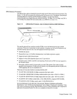
blower module
is
available
as
spare
The
chapter
Maintaining
the
Router
provides
blower module
replacement
instructions
Note
The
front-panel
LEDs
are located
inside
the
blower
module
If
one
of these
LEDs
fails
the
entire
blower module
assembly
must be
replaced
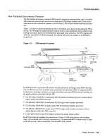
Chassis
Interface
The
chassis interface
provides
the environmental
monitoring
ENYM
and power
supply
monitoring
functions
for the Cisco
7513
The
chassis interface
isolates
the
CPU
and system
software
from
chassis-specific
variations
The
chassis interface
is
part of the backplane
assembly
and
is
not
available
separately
as
spare
part
or
FRU
Following
are the functions
of the chassis interface
Report
backplane
type
Report
arbiter
type
Monitor power
supply
status
Monitor
fan/blower
status
Monitor
temperature
sensors
on
the
RSP2
Provide
router
power
up/down
control
Provide
power
supply
power-down
control
Provide
override
for
system blower
speed
control
Monitor power
supply
currents
1-10
Cisco
7513
Hardware
Installation
and
Maintenance
Содержание 7513 Series
Страница 1: ......
Страница 11: ...Cisco 7513 Hardware Installation and Maintenance ...
Страница 121: ...Site Log 2 56 Cisco 7513 Hardware Installation and Maintenance ...
Страница 162: ...Troubleshooting the Processor Subsystem 4 10 Cisco 7513 Hardware Installation and Maintenance ...
Страница 266: ...Interface Processor LEDs B 16 Cisco 7513 Hardware Installation and Maintenance ...
Страница 270: ...C 4 Cisco 7513 Hardware Installation and Maintenance ...
Страница 288: ...18 Cisco 7513 Hardware Installation and Maintenance ...


