


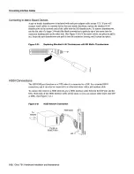


Connecting
Interface
Cables
Mixed
modeFollow
the cabling
guidelines
described
in
the
sections
Single
Attachment
Connections
and
Dual
Attachment
Connections
to
connect
the
multimode and
single-mode
interface
cables
Figure
3-16
shows
that
the primary
ring signal
is
received
on
the
multimode
PHY
receive
port
and
transmitted
from
the
single-mode
PHY
transmit
port
Your
configuration
may
be
opposite
with
multimode on
PHY
and
single-mode
on
PHY
Connect
the cables
to
the
HP
ports
as
follows
Connect
the cable
coming
in
from
the primary
ring
to
the
PHY
receive
port and
connect
the signal going
out
to
the secondary
ring
to
the
PHY
transmit
port
Connect
the cable
coming
in
from
the secondary
ring
to
the
PHY
receive
port
This
also
connects
the signal
going
out
to
the primary
ring
to
the
PHY
transmit
port
Figure
3-16
FDDI
Dual Attachment
Network
Connections
Single-Mode
and
Multimode
Mixed-mode
configurations
Use
multimode
and
To
single-mode
single-mode
cables
network
Receive
for
mixed-mode
configurations
To
multimode
network
If
you
are connecting
an
optical bypass
switch
proceed
to
the next
section
Otherwise
proceed
to
Connecting
the
Console
Terminal
in
this
chapter
FC
connectors
Transmit
MIC
FIP
3-18
Cisco
7513
Hardware
Installation
and
Maintenance
Содержание 7513 Series
Страница 1: ......
Страница 11: ...Cisco 7513 Hardware Installation and Maintenance ...
Страница 121: ...Site Log 2 56 Cisco 7513 Hardware Installation and Maintenance ...
Страница 162: ...Troubleshooting the Processor Subsystem 4 10 Cisco 7513 Hardware Installation and Maintenance ...
Страница 266: ...Interface Processor LEDs B 16 Cisco 7513 Hardware Installation and Maintenance ...
Страница 270: ...C 4 Cisco 7513 Hardware Installation and Maintenance ...
Страница 288: ...18 Cisco 7513 Hardware Installation and Maintenance ...


