background image

Connecting Power to the Router

viii

Cisco 1750 Router Hardware Installation Guide

78-6169-02

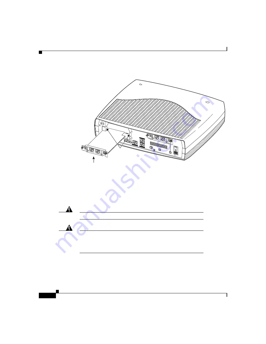
Figure 3

Inserting a WIC or VIC in the Router

Connecting Power to the Router

Read the following warnings before connecting the power to the router.

Warning

The power supply is designed to work with TN power systems.

Warning

This product relies on the building’s installation for short-circuit 
(overcurrent) protection. Ensure that a fuse or circuit breaker no 
larger than 120VAC, 15AU.S. (240VAC, 16A international) is used on 
the phase conductors (all current-carrying conductors).

17477

Interface card

+5, +12, -12 

VDC

CONSOLE

AUX

Cisco 1750

10/100 E

THERN

ET

SEE M

ANU

AL B

EFOR

E IN

STAL

LATIO

N

VIC

2FXO

PVD

M OK

SLO

T 1 

SLO

T 2 O

K

FDX

SLO

T 0 O

K

SLO

T 1 OK

100

LINK

SLOT

 2

THIS S

LOT A

CCEP

TS O

NLY V

OICE IN

TERFA

CE C

ARDS

SLOT 0

1

IN USE

0

IN USE

Guides

SEE M

ANU

AL B

EFOR

E INS

TALL

ATIO

N

VIC

2FXS

1

IN USE

0

IN USE

Содержание 1750

Страница 1: ... 95134 1706 USA http www cisco com Cisco Systems Inc Corporate Headquarters Tel 800 553 NETS 6387 408 526 4000 Fax 408 526 4100 Cisco 1750 Router Hardware Installation Guide Customer Order Number DOC 786169 Text Part Number 78 6169 02 ...

Страница 2: ...difying the equipment without Cisco s written authorization may result in the equipment no longer complying with FCC requirements for Class A or Class B digital devices In that event your right to use the equipment may be limited by FCC regulations and you may be required to correct any interference to radio or television communications at your own expense You can determine whether your equipment ...

Страница 3: ...t Quotient IOS IP TV iQ Expertise the iQ logo iQ Net Readiness Scorecard LightStream Linksys MeetingPlace MGX the Networkers logo Networking Academy Network Registrar Packet PIX Post Routing Pre Routing ProConnect RateMUX ScriptShare SlideCast SMARTnet StrataView Plus TeleRouter The Fastest Way to Increase Your Internet Quotient and TransPath are registered trademarks of Cisco Systems Inc and or i...

Страница 4: ......

Страница 5: ...xiv C H A P T E R 1 Cisco 1750 Router Overview 1 i Key Features 1 ii Rear Panel Ports and LEDs 1 iv Front Panel LEDs 1 vi Router Memory 1 ix Types of Memory 1 ix Amounts of Memory 1 x Unpacking the Router 1 xi Additional Required Equipment 1 xi C H A P T E R 2 Installation 2 i Before Installing the Router 2 i Connecting the Router to Your Local Network 2 ii Installing WICs and VICs 2 v Safety Info...

Страница 6: ...g a Lost Password 3 ii Changing the Configuration Register 3 ii Resetting the Router 3 iv Resetting the Password 3 v Resetting the Configuration Register Value 3 vi Problem Solving 3 vi OK LED Diagnostics 3 vii Troubleshooting WICs and VICs 3 viii Troubleshooting the Power System 3 x Troubleshooting ISDN 3 xi A P P E N D I X A Technical Specifications A i A P P E N D I X B Cabling Specifications B...

Страница 7: ...nd Upgrading Memory and Data Modules C i Safety Information C i Opening the Chassis C iii Locating Modules C v Installing a Mini Flash Module C vi Removing a Mini Flash Module C vi Installing a Dual In Line Memory Module C ix Installing a Packet Voice Data Module C x Closing the Chassis C xi I N D E X ...

Страница 8: ...Contents viii Cisco 1750 Router Hardware Installation Guide 78 6169 02 ...

Страница 9: ...y instructions and information You can access Cisco documentationand additional literature on the World Wide Web at http www cisco com http www china cisco com or http www europe cisco com If you are reading Cisco product documentation on the World Wide Web you can submit comments electronically Click Feedback in the toolbar and select Documentation After you complete the form click Submit to send...

Страница 10: ...ectors Chapter 2 Installation describes how to install the router by connecting cables power and install WAN interface cards WICs and voice interface cards VICs Chapter 3 Troubleshooting describes some problems that you might have with the router and how to solve these problems Appendix A Technical Specifications lists the physical characteristics environmental requirements and power specification...

Страница 11: ... WICs and VICs that are supported by the Cisco 1750 router Cisco IOS command reference and configuration guides provide complete information about all Cisco IOS CLI commands and how to use them as well as information on designing and configuring LANs and WANs Conventions This guide uses the following conventions for instructions and information Notes Cautions and Warnings Notes cautions and warnin...

Страница 12: ... sähkökytkentöihin liittyvistä vaaroista ja tavanomaisista onnettomuuksien ehkäisykeinoista Attention Ce symbole d avertissement indique un danger Vous vous trouvez dans une situation pouvant causer des blessures ou des dommages corporels Avant de travailler sur un équipement soyez conscient des dangers posés par les circuits électriques et familiarisez vous avec les procédures couramment utilisée...

Страница 13: ... a trabalhar com qualquer equipamento familiarize se com os perigos relacionados com circuitos eléctricos e com quaisquer práticas comuns que possam prevenir possíveis acidentes Atención Este símbolo de aviso significa peligro Existe riesgo para su integridad física Antes de manipular cualquier equipo considerar los riesgos que entraña la corriente eléctrica y familiarizarse con los procedimientos...

Страница 14: ...n square brackets are optional x x x A choice of keywords represented by x appears in braces separated by vertical bars You must select one or Ctrl Represent the key labeled Control For example when you read D or Ctrl D you should hold down the Control key while you press the D key screen font Examples of information displayed on the screen boldface screen font Examples of information that you mus...

Страница 15: ...view This chapter introduces the Cisco 1750 router also referred to in this guide as the router and covers the following topics Key Features Rear Panel Ports and LEDs Front Panel LEDs Router Memory Unpacking the Router Additional Required Equipment Figure 1 shows the Cisco 1750 router ...

Страница 16: ...er an IP network Using one to four WAN connections the router links small to medium size remote Ethernet and FastEthernet LANs to central offices Table 1 lists the router key features 17468 PWR ACT PORT0 PORT1 PORT1 OK PORT0 SLOT1 PORT0 SLOT0 SLOT2 ETH PORT1 COL Cisco 1700 S E R I E S ROUTER Table 1 Key Features Feature Description One FastEthernet 10 100BaseTX port Operates in full or half duplex...

Страница 17: ...nection to the router which can be configured and managed from a remote location Supports up to 115 2 kbps Security slot Supports Kensington or similar lockdown equipment SNMP support Supports Simple Network Management Protocol SNMP to manage the router over a network AutoInstall support Supports AutoInstall to download configuration files to the router over a WAN connection Cisco ConfigMaker supp...

Страница 18: ...the same speed and in the same duplex mode Auxiliary port AUX black Modem connection for remote configuration using Cisco IOS software Console port CONSOLE light blue Terminal or PC connection for local configuration using Cisco IOS software 5 12 12 VDC CONSOLE AUX Cisco 1750 10 100 ETHERNET SLOT 2 SEE MANUAL BEFORE INSTALLATION 1 IN USE VIC 2FXO PVDM OK SLOT 1 SLOT 2 OK FDX SLOT 0 OK SLOT 1 OK 10...

Страница 19: ...refer to the Cisco WAN Interface Cards Hardware Installation Guide that comes with every card Power socket 5 12 12 VDC Router connection to the external power supply Protective earth Ground wire Router connection to earth ground by using a green and yellow 14 AWG ground wire Table 2 Rear Panel Connectors continued Connector Slot Label Color Description Table 3 Rear Panel LEDs LED Label Color Descr...

Страница 20: ... a packet voice data module PVDM is correctly inserted in the card slot Table 3 Rear Panel LEDs continued LED Label Color Description 17470 PWR ETH ACT PORT0 PORT1 PORT1 OK PORT0 SLOT1 PORT0 SLOT0 SLOT2 PORT1 COL Table 4 Front Panel LEDs LED Color Cards Supported LED Meaning PWR Green On when DC power is being supplied to the router OK Green On when the router has successfully booted up and the so...

Страница 21: ...TØ Green ISDN On when the first ISDN B channel is connected Serial and CSU DSU Blinks when data is being sent to or received from the port 2 port serial VIC 2E M VIC 2FXO VIC 2FXS PORT1 Serial and CSU DSU Off Green ISDN On when the first ISDN B channel is connected 2 port serial Blinks when data is being sent to or received from the port VIC 2E M VIC 2FXO VIC 2FXS Table 4 Front Panel LEDs continue...

Страница 22: ...XS PORT1 Serial and CSU DSU Off Green ISDN On when the first ISDN B channel is connected 2 port serial Blinks when data is being sent to or received from the port VIC 2E M VIC 2FXO VIC 2FXS SLOT2 PORTØ Green VIC 2E M Blinks when data is being sent to or received from the port VIC 2FXO VIC 2FXS PORT1 Green VIC 2E M Blinks when data is being sent to or received from the port VIC 2FXO VIC 2FXS Table ...

Страница 23: ... also called working storage and contains the dynamic configuration information The router stores a working copy of Cisco IOS software dynamic configuration information and routing table information in DRAM Nonvolatile RAM NVRAM This type of memory contains the startup configuration Flash memory This special kind of erasable programmable memory contains a copy of the Cisco IOS software The Flash m...

Страница 24: ...led Mon 22 Mar 99 12 58 by syaji Image text base 0x80008088 data base 0x806B2BB8 ROM System Bootstrap Version 12 0 1 XA1 RELEASE SOFTWARE fc1 Router uptime is 15 minutes System restarted by power on System image file is flash syaji c1700 sv3y mz cisco 1750 MPC860 processor revision 0x00 with 24576K 8192K bytes of memory Processor board ID 0000 1314672220 with hardware revision 0000 M860 processor ...

Страница 25: ...itional Required Equipment Equipment When You Use It Ethernet hub A hub connects pieces of network equipment including the router to create a network You can use a 10 100 or 10 100 Mbps hub with the router Ethernet switch A switch connects pieces of network equipment including the router to create a network You can use a 10 100 or 10 100 Mbps switch with the router Phillips screwdriver Although th...

Страница 26: ...1 telephone cable This cable connects the VIC to a telephone fax machine or a telephone wall jack You will need one cable for each of these connections Standard RJ 48 telephone cable This cable connects the VIC to a PBX trunk line You will need one cable for each of these connections Serial cable This cable connects a serial card to serial services You must order this cable from Cisco For detailed...

Страница 27: ...r Local Network Installing WICs and VICs Connecting Power to the Router Verifying Your Installation Optional Installation Steps Before Installing the Router The router is shipped ready for desktop mounting Before making the power and network connections simply set the router on a desktop shelf or other flat surface Note For instructions on wall mounting the router refer to the Wall Mounting sectio...

Страница 28: ...iods of lightning activity Caution Do not place anything on top of the router that weighs more than 10 pounds 4 5 kg Excessive weight on top of the router could damage the chassis Connecting the Router to Your Local Network The router is connected to your local Ethernet network through the yellow 10 100 Ethernet port You must provide the following items for this connection A straight through RJ 45...

Страница 29: ...ion Always connect the Ethernet cable to the yellow ports on the router Do not connect the cable to an ISDN S T or U port on a WIC or to an NT1 that is connected to a WIC Accidently connecting the cable to the wrong port can damage your router Follow these steps to connect the router to your local network Step 1 Connect one end of the cable to the yellow Ethernet port labeled 10 100 Mbps Ethernet ...

Страница 30: ...b or switch 10 100 or 10 100 Mbps 5 12 12 VDC CONSOLE AUX Cisco 1750 10 100 ETHERNET SEE MA NUAL BEF ORE INS TAL LAT ION VIC 2FX O PVDM OK SLOT 1 SLOT 2 OK FDX SLOT 0 OK SLOT 1 OK 100 LINK SLOT 2 THIS SLO T ACCEPTS ONLY VOICE INTERFAC E CARDS SLOT 0 1 IN USE 0 IN USE SEE MA NUAL BEF ORE INS TAL LAT ION VIC 2FX S 1 IN USE 0 IN USE MDI MDI X 5X 6X 7X 8X 1X 2X 3X 4X 10 100 1 SPEED 100BaseTX 10BaseT L...

Страница 31: ...me with the card s Safety Information This section lists safety warnings that you should be aware of before installing WICs or VICs in the router To see translated versions of these warnings refer to the Regulatory Compliance and Safety Information for the Cisco 1600 and Cisco 1700 Routers document that came with the router Warning Before working on a system that has an on off switch turn off the ...

Страница 32: ...htning activity Caution Do not connect a WAN telephone or fax cable to the card until you have completed the installation procedure Follow these steps to remove and insert a card in the router Step 1 Make sure the router is turned off and is disconnected from the power supply Step 2 Loosen the thumbscrews on the WIC or VIC slot cover on the rear panel as shown in Figure 2 You should be able to loo...

Страница 33: ...t as shown in Figure 3 Step 5 Insert the card in the slot and gently push it into the router until the front panel of the card is flush with the rear panel of the router Step 6 Tighten the screws 17475 Interface card slot cover 5 12 12 VDC CONSOLE AUX Cisco 1750 10 100 ETHERNET SEE MA NUAL BEFORE INS TALLA TIO N VIC 2FXO PVDM OK SLOT 1 SLOT 2 OK FDX SLOT 0 OK SLOT 1 OK 100 LINK SLOT 2 THIS SLOT AC...

Страница 34: ...building s installation for short circuit overcurrent protection Ensure that a fuse or circuit breaker no larger than 120VAC 15AU S 240VAC 16A international is used on the phase conductors all current carrying conductors 17477 Interface card 5 12 12 VDC CONSOLE AUX Cisco 1750 10 100 ETHERNET SEE MA NUAL BEFORE INS TAL LAT ION VIC 2FX O PVDM OK SLOT 1 SLOT 2 OK FDX SLOT 0 OK SLOT 1 OK 100 LINK SLOT...

Страница 35: ...rd to the socket on the power supply Step 3 Connect the other end of the separate power cord to a power outlet Step 4 Press the router power switch to on Step 5 Confirm that the router has power by checking that the PWR LED on the front panel is on Figure 4 Connecting the Power Supply 5 12 12 VDC CONSOLE AUX Cisco 1750 10 100 ETHERN ET SEE MAN UAL BEF ORE INS TAL LAT ION VIC 2FX O PVDM OK SLOT 1 S...

Страница 36: ... Activity on PORTØ and PORT1 of each of these slots varies depending on the type of WIC or VIC installed Refer to Table 4 in the Cisco 1750 Router Overview chapter for detailed information on activity at different ports SLOT 0 and SLOT 1 OK rear panel On when a WIC or VIC is correctly installed in the slot SLOT 2 OK rear panel On when a VIC is correctly installed in the slot LINK rear panel On whe...

Страница 37: ...uld be configured with the following parameters 9600 baud 8 data bits no parity 1 stop bit no flow control Refer to the Cisco 1700 Router Software Configuration Guide for detailed information about configuring the router using Cisco IOS software Follow these steps to connect the router to a terminal or PC Step 1 Connect the light blue console cable to the blue Console port on the router as shown i...

Страница 38: ...2 12 VDC CONSOLE AUX Cisco 1750 10 100 ETHERNET SEE MA NUAL BEFORE INS TALLATION VIC 2FXO PVDM OK SLOT 1 SLOT 2 OK FDX SLOT 0 OK SLOT 1 OK 100 LINK SLOT 2 THIS SLOT ACCEPTS ONLY VOICE INTERFACE CARDS SLOT 0 1 IN USE 0 IN USE SEE MA NUAL BEFORE INS TALLATION VIC 2FXS 1 IN USE 0 IN USE 17481 Console port Light blue console cable To PC or terminal ...

Страница 39: ...r Step 1 Connect one end of the cable to the black AUX port on the router rear panel Step 2 Connect the adapter labeled Modem to the other end of the cable Step 3 Connect the DB 25 end of the adapter to the modem Figure 6 Connecting a Modem to the Router 5 12 12 VDC CONSOLE AUX Model Cisco 1750 10 100 ETHERN ET SEE MA NUA L BEF ORE INS TAL LAT ION VIC 2FX O PVDM OK MOD OK SLOT 1 SLOT 2 OK FDX SLOT...

Страница 40: ...ches 9 52 centimeters horizontally apart on a wall or other vertical surface The screws should protrude 0 25 inches 0 64 centimeters from the surface of the wall Step 2 Hang the router on the screws with either the left side or right side mounting brackets so that The LEDs are visible to the user The LEDs indicate the router operating status so the LEDs should be easily visible The power supply do...

Страница 41: ...tallation Steps Caution If you install the screws in drywall use hollow wall anchors 1 8 inch by 5 16 inch to secure the screws If the screws are not properly anchored the strain of the cables connected to the router rear panel connectors could pull the router from the wall ...

Страница 42: ...Optional Installation Steps xvi Cisco 1750 Router Hardware Installation Guide 78 6169 02 ...

Страница 43: ...or Your Reseller Recovering a Lost Password Problem Solving Contacting Cisco or Your Reseller If you cannot locate the source of a problem contact your local reseller for advice Before you call you should have the following information ready Chassis type and serial number Maintenance agreement or warranty information Cisco IOS release installed on your router Date you received the router Brief des...

Страница 44: ... the Configuration Register Value Note See the Hot Tips section on Cisco Connection Online CCO for additional information on replacing enable secret passwords Changing the Configuration Register Follow these steps to change the configuration register Step 1 Connect an ASCII terminal or a PC running a terminal emulation program to the console port on the rear panel of the router Refer to the sectio...

Страница 45: ...TWARE fc1 Router uptime is 15 minutes System restarted by power on System image file is flash syaji c1700 sv3y mz cisco 1750 MPC860 processor revision 0x00 with 24576K 8192K bytes of memory Processor board ID 0000 1314672220 with hardware revision 0000 M860 processor part number 0 mask 32 Bridging software X 25 software Version 3 0 0 1 FastEthernet IEEE 802 3 interface s 2 Low speed serial sync as...

Страница 46: ...tation that came with the terminal for instructions on how to send a break To send a break in Windows HyperTerminal enter Ctrl Break Step 2 Send a break The terminal displays the following prompt rommon 2 Step 3 Enter confreg 0x142 to reset the configuration register rommon 2 confreg 0x142 Step 4 Initialize the router by entering the reset command rommon 2 reset The router resets and the configura...

Страница 47: ...complete the password recovery process by performing the steps in the next section Resetting the Configuration Register Value If you are recovering an enable secret password you will not see the display in the show startup config command output Complete the password recovery process by performing the steps in the following Resetting the Password section Resetting the Password Follow these steps to...

Страница 48: ...outer config Ctrl Z Step 4 Reboot the router and enter the recovered password Problem Solving The key to problem solving is to isolate the problem to a specific subsystem by comparing what the router is doing to what it should be doing When problem solving consider the following subsystems of the router WICs and VICs Refer to the LEDs on the cards and the LEDs on the router front panel to help ide...

Страница 49: ...he OK LED blinks in a different pattern described in Table 1 depending on the problem A pattern is a specific number of blinks that is repeated until the router is turned off If the router experiences any of these problems contact your Cisco reseller Table 1 OK LED Blinking Patterns Number of Blinks Meaning 2 The 860T dual port RAM DPRAM failed 3 The parameter RAM area of the 860T DPRAM failed 4 T...

Страница 50: ... 0 Serial 2A S 12in1 WAN daughter card Hardware revision 1 0 Board revision A0 Serial number 0007947084Part number 800 03182 01 Test history 0x00 RMA number 00 00 00 Connector type PCI EEPROM format version 1 EEPROM contents hex 0x20 01 13 01 00 00 79 43 4C 50 0C 6E 01 00 00 00 00 0x30 50 00 00 00 98 04 17 17 FF FF FF FF FF FF FF FF WIC Slot 1 Dual FXS Voice Interface Card WAN daughter card Hardwa...

Страница 51: ...ter Router recognizes the card s but the card port s do not initialize Make sure that the card is correctly installed in the router Refer to the Installing WICs and VICs section in the Installation chapter Check the external cable connections to make sure they are secure Router does not boot properly or continuously or intermittently reboots Make sure that the WIC or VIC is correctly installed in ...

Страница 52: ...ight be a problem with the WIC or VIC cables Consult your Cisco reseller for warranty information Table 2 Troubleshooting WICs and VICs continued Symptom Possible Solution s Table 3 Troubleshooting the Power System Symptom Possible Solution s Router shuts down after being on for a short time Make sure that the area in which the router is installed meets the environmental site requirements in the T...

Страница 53: ...terface bri1 For routers with an ISDN U WIC use the clear controller command to terminate any active ISDN calls to reset the ISDN BRI interface and to reset the ISDN line between the router and the central office switch Do this for each ISDN port installed in the router Router clear controller bri0 Router clear controller bri1 Table 4 lists troubleshooting methods for ISDN specific problems that m...

Страница 54: ...perly connected If yes the ISDN line might be malfunctioning Check with your ISDN service provider Is the NT1 LED on If no the NT1 might be malfunctioning ISDN U Router is on but the NT1 LED on the card is off Is the OK LED on If no the router might be malfunctioning Contact your Cisco reseller Are all ISDN cables properly connected If yes the ISDN line might be malfunctioning Check with your ISDN...

Страница 55: ...ages contact the service provider If Layer 1 status is active does Layer 3 status say 2 Active Layer 3 calls Router might have called itself Check destination phone number configured with the dialer map command or the dialer string command If Layer 1 status is active does Layer 3 status say No Active Layer 3 call s Check destination phone number and make sure it matches the remote router phone num...

Страница 56: ...Problem Solving xiv Cisco 1750 Router Hardware Installation Guide 78 6169 02 ...

Страница 57: ...e 1 Router Specifications Description Specification Console port RJ 45 Auxiliary port RJ 45 Ethernet port RJ 45 Dimensions H x W x D 4 x 11 2 x 8 7 in 10 16 x 28 45 x 22 10 cm Weight Weight without the cards Weight with three interface cards 3 lb 1 4 kg 3 5 lb 1 75 kg Power supply External On board Universal AC DC switching Supplies 5V 12V and 12V Supplies 3 3V and 5V ...

Страница 58: ...8 6169 02 Power consumption 18W Operating Specifications Operating temperature Storage temperature Operating humidity 32 to 104 F 0 to 40 C 40 to 149 F 20 to 65 C 10 to 85 noncondensing Table 1 Router Specifications continued Description Specification ...

Страница 59: ...te For detailed information about cables used with Cisco WICs and VICs refer to the Cisco WAN Interface Cards Hardware Installation Guide that comes with each of the cards Ethernet Cables This section describes the Ethernet cables that are used to connect the router to your local Ethernet network A 10 100BaseTX router like the Cisco 1750 router requires Category 5 unshielded twisted pair UTP or sh...

Страница 60: ...r of the network equipment Table 1 Straight Through Ethernet Cable RJ 45 to RJ 45 Pinouts RJ 45 Pin1 Signal Direction RJ 45 Pin 1 TX 1 2 TX 2 3 RX 3 6 RX 6 1 Pins 4 5 7 and 8 are not used for signaling but to reduce radiated cable emissions Table 2 Ethernet Cabling Guidelines Specification 10BaseT 100BaseTX Maximum segment length 100 meters 100 meters Maximum number of segments per network 5 With ...

Страница 61: ...s This table also includes pinouts for a DB 9 to RJ 45 console adapter Maximum hop count1 4 With Class I repeaters none With Class II repeaters 1 Maximum number of nodes per segment 1024 1024 Cable type required UTP Category 3 4 or 5 UTP Category 5 or STP 1 Hop count Routing metric used to measure the distance between a source and a destination Table 2 Ethernet Cabling Guidelines continued Specifi...

Страница 62: ... Identifying a Rollover Cable TXD 3 6 2 3 RXD GND 4 5 5 7 GND GND 5 4 5 7 GND RXD 6 3 3 2 TXD DSR 7 2 4 20 DTR CTS 8 1 7 4 RTS Table 3 Console Cable and Adapter Pinouts continued Console DTE Console Port Console Cable Adapter Adapter Terminal DTE Signal RJ 45 Pin RJ 45 Pin DB 9 Pin DB 25 Pin Signal Pin 1 H10632 Pin 8 Pin 1 on one connector and pin 8 on the other connector should be the same color ...

Страница 63: ...ports color coded pink to the PSTN or to a PBX that does not support E M signaling Standard RJ 48S connector and cable to connect E M VIC ports color coded brown to a PBX line The cable wiring depends on the PBX type and connection For details refer to the Cisco WAN Interface Cards Hardware Installation Guide Figure 2 shows how to connect the VICs to the network Figure 2 Connecting VICs to the Net...

Страница 64: ... connection Table 5 lists the pinout for this connector Note Pins that are not used should not be connected Table 4 RJ 11 Pinout Pin Signal 1 2 3 Ring 4 Tip 5 6 Table 5 E M Pinouts Pin Signal Description 1 SB 48V signaling battery 2 M lead Signaling input 3 R Ring audio input 4 R or R1 Ring audio input output or output 5 T or T1 Tip audio input output or output 6 T Tip audio input ...

Страница 65: ...vii Cisco 1750 Router Hardware Installation Guide 78 6169 02 VIC Cables and Pinouts 7 E lead Signaling output 8 SG Signaling ground return Table 5 E M Pinouts continued Pin Signal Description ...

Страница 66: ...VIC Cables and Pinouts viii Cisco 1750 Router Hardware Installation Guide 78 6169 02 ...

Страница 67: ...owing sections Opening the Chassis Locating Modules Installing a Mini Flash Module Installing a Dual In Line Memory Module Installing a Packet Voice Data Module Closing the Chassis Safety Information This section contains safety information that you should read before installing or upgrading memory in the router Warning Before working on a system that has an on off switch turn off the power and un...

Страница 68: ...n the power cord is connected Warning Before working on equipment that is connected to power lines remove jewelry including rings necklaces and watches Metal objects will heat up when connected to power and ground and can cause serious burns or weld the metal object to the terminals Warning Only trained and qualified personnel should be allowed to install or replace this equipment Warning Hazardou...

Страница 69: ...s screwdriver Follow these steps to open the chassis Step 1 Make sure the router is turned off and is disconnected from the power supply Step 2 Turn the router upside down and rest the top of the router on a flat surface Step 3 Use the Phillips screwdriver to remove the four screws that hold the top and bottom of the chassis together as shown in Figure 1 Step 4 Turn the router back to its original...

Страница 70: ...n cable from the connector labeled FAN on the motherboard Step 6 Place the router bottom on an antistatic mat and begin installing memory 5 12 1 2 V D C C O N S O L E A U X C i s c o 1 7 5 0 10 1 00 E T H E R N E T S E E M A N U A L B E FO R E IN S TA LL A TI O N V IC 2 F X O PV D M O K SL O T 1 SL O T 2 O K FD X SL O T 0 O K SL O T 1 O K 10 0 LI N K SL O T 2 T H IS S LO T A C C E P T S O N LY V O...

Страница 71: ...ine memory module DIMM a packet voice data module PVDM and a mini Flash memory module on the motherboard The mini Flash memory module is on the back of the motherboard Figure 2 Cisco 1750 Motherboard Module Locations DIMM slot 22312 WIC VIC slot 1 top WIC VIC slot 0 bottom PVDM slot Mini Flash module slot back of motherboard VIC slot 2 ...

Страница 72: ... router Figure 3 Mini Flash Module Removing a Mini Flash Module Follow these steps to remove a mini Flash memory module Note You need to remove the motherboard from the chassis to remove the mini Flash memory module Warning During this procedure wear grounding wrist straps to avoid ESD damage to the router Do not directly touch the backplane with your hand or any metal tool or you could shock your...

Страница 73: ... The mini Flash memory module is on the back of the motherboard Step 2 Insert your index finger between the mini Flash memory module and the mini Flash memory module release lever as shown in Figure 4 Step 3 Firmly pull the release lever away from the module until the module pops up and away from the module slot Figure 4 Removing a Mini Flash Module 22308 Mini Flash module release lever ...

Страница 74: ... module Step 1 Locate the module slot on the motherboard shown in Figure 2 Step 2 Hold the module with the notched edge away from you Step 3 Insert the module into the module slot at a 45 degree angle as shown in Figure 5 Step 4 Press down firmly on the module until you hear a clicking sound and the module is firmly seated in the slot Step 5 Turn the motherboard back to its original position right...

Страница 75: ...lot on the motherboard shown in Figure 2 Step 2 Remove any existing DIMM by pulling the DIMM slot guides shown in Figure 6 away from the DIMM and down towards the motherboard Step 3 Hold the replacement DIMM with the notched edge away from you and facing the router Step 4 Insert the DIMM into the DIMM slot making sure that the notches on the edge of the DIMM are inserted over the bars inside the D...

Страница 76: ...ny metal tool or you could shock yourself Step 1 Locate the PVDM slot on the motherboard shown in Figure 2 Step 2 Remove any existing PVDM by pulling the PVDM snaps shown in Figure 7 away from the PVDM Step 3 Hold the replacement PVDM with the double notched edge on your left Step 4 Insert the PVDM into the PVDM slot making sure that the notches on the edge of the PVDM are inserted over the bars i...

Страница 77: ...he Chassis section reconnect the fan cable to the connector labeled FAN on the motherboard Step 2 Locate the posts that protrude from the inside of the chassis cover and the corresponding openings on the chassis bottom Step 3 Line up the posts with the corresponding openings as shown in Figure 8 and carefully slide the posts into the openings Be careful not to damage the router motherboard with th...

Страница 78: ... xii Cisco 1750 Router Hardware Installation Guide 78 6169 02 Figure 8 Closing the Chassis 22311 SEE MANUAL BEFO RE IN STA LL ATION VIC 2FXO 1 IN USE 0 IN USE SEE MANUAL BEFO RE IN STA LL ATION VIC 2FXS 1 IN USE 0 IN USE ...

Страница 79: ... 2 xi B iii Ethernet 2 ii B i included with router 1 xi required 1 xi rollover B iv serial 1 xii specifications B i VIC B v caution described xi chassis closing C xi dimensions A i opening C iii Cisco contacts 3 i Cisco ConfigMaker support 1 iii Cisco Networked office stack 1 iii clear controller command 3 xi clear interface command 3 xi closing chassis C xi command conventions xiv commands clear ...

Страница 80: ...connectors rear panel 1 iv console port connecting 2 xi featured 1 iii 1 iv illustrated 1 iv specifications A i contacts Cisco and reseller 3 i conventions command xiv text xi copy command 3 vi D dialer map command 3 xiii dialer string command 3 xiii digital signal processor C x DIMM installing C ix locating on router C v documentation included x DRAM overview 1 ix DSP C x E E M VIC port B v enabl...

Страница 81: ...uter C v overview 1 ix front panel illustrated 1 vi LEDs 1 vi FXO VIC port B v FXS VIC port B v G ground wire 1 v H hardware specifications A i I indicators see LEDs installation equipment you provide 1 xi router 2 i verifying using LEDs 2 x installing DIMM C ix Flash memory C vi memory C i PVDM C x voice interface cards 2 v wall mounting 2 v WAN interface cards 2 v interface cards featured 1 iii ...

Страница 82: ...w 1 ix installing and upgrading C i router 1 ix mini Flash module installing C vi removing C vi modem connecting to router 2 xiii required 1 xii support 1 iii module DIMM installing C ix locating on router C v mini Flash installing C vi locating on router C v PVDM installing C x locating on router C v mounting wall 2 xiv N note described xi NT1 1 xii NVRAM overview 1 ix O OK LED described 1 vi dia...

Страница 83: ...FXS VIC B v rear panel 1 iv power socket connecting 2 ix described 1 v illustrated 1 iv problem solving 3 vi specifications A i troubleshooting 3 x problem solving router 3 vi Protective earth 1 v publications see documentation PVDM installing C x R rear panel connectors 1 iv ports 1 iv required equipment 1 xi reset command 3 iv resetting the router 3 iv rollover cable B iv router connecting to a ...

Страница 84: ... A i terminal emulation settings 2 xi text conventions xi troubleshooting contacts 3 i ISDN 3 xi OK LED 3 vii password recovery 3 ii power system 3 x WICs and VICs 3 viii U unpacking the router 1 xi to 1 xi V verifying installation 2 x voice interface cards installing 2 v pinout B v problem solving 3 vi required 1 xii router slots 1 v supported cards 1 iii troubleshooting 3 viii voice support 1 ii...

Отзывы: