DS632F1
33
CS44800
ger (addresses 09h - 10h)” on page 58
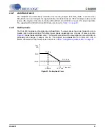
. Volume control changes are programmable to ramp in increments
of 0.125 dB at a variable rate controlled by the SZC[1:0] bits.
Each PWM channel output can be independently muted via mute control bits in the register
“Channel Mute
(address 13h)” on page 60
.
When enabled, each CHXX_MUTE bit attenuates the corresponding PWM channel to its maximum value
(-127 dB). When the CHXX_MUTE bit is disabled, the corresponding PWM channel returns to the atten-
uation level set in the Volume Control register. The attenuation is ramped up and down at the rate spec-
ified by the SZC[1:0] bits.
4.5.4
Peak Detect / Limiter
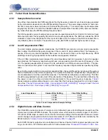
The CS44800 has the ability to limit the maximum signal amplitude to prevent clipping. The
“Peak Limiter
Control Register (address 15h)” on page 60
is used to configure the peak detect and limiter engines’ op-
eration. Peak Signal Limiting is performed by digital attenuation. The attack rate is determined by the
“Lim-
iter Attack Rate (address 16h)” on page 61
. The release rate is determined by the
“Limiter Release Rate
(address 17h)” on page 61
.
4.5.5
PWM Engines
There are
four
stereo PWM Engines: PWM_ENG_1, PWM_ENG_2, PWM_ENG_3 and PWM_ENG_4.
Each PWM can handle one stereo pair and connects to a driver or a pair of drivers, depending on the
output configuration. Each PWM Engine receives the master clock, PWM_MCLK, from the Clock Control
block, and the associated channel data and audio sample timings from the Sample Rate Converter.
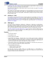
The
“PWM Configuration Register (address 31h)” on page 68
is used to configure the PWM engines’ op-
eration. This register controls the parameters of the PWM engines and can only be changed while the
PWM engines are in the power down state.
Features:
•
Up to
8
channel support
•
64 Quantization levels
•
PSRR compensation feedback
•
Programmable Over Sampling - interpolate times 2 (2x) or filter by-pass. By-pass is intended for
384 kHz (single-speed) PWM switch rate support. The interpolate 2x filter is used to upsample the data
to support a PWM switch rate of 768 kHz (double speed mode). This enables the output frequency re-
sponse to extend past 20 kHz when the DAI sample rate is 96 kHz or 192 kHz.
•
Programmable registers to move PWM edges for delay adjustment. This lowers the overall noise con-
tribution by allowing each PWM edge to switch at different times.
•
Programmable Modulation Setup
–
Min/Max PWM pulse width allowed
–
Programmable Modulation index.
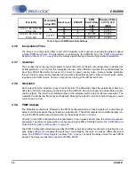
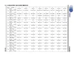
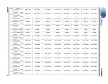
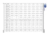
The table below shows the available settings for the PWM Engine for a 384 kHz/768 kHz or
421.875 kHz/843.75 kHz PWM Fswitch rate verses the supported Fsin sample rates using the SRC with
a maximum PWM_MCLK of 49.152 MHz/54 MHz.

