background image

44

BLITZ

5-1996

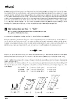
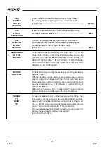
TABLE SUMMARIZING THE NECESSARY OPERATIONS FOR ADJUSTING THE MACHINE

TO DETERMINE

TO STATE

3

 TO OBTAIN

4

 TO STATE

5

 TO OBTAIN

WORKING

FEED

WORKED SURFACE

LITRES PER

SPRAYING CAPA-

WIDTH

SPEED

PER HOUR

HECTARE

CITY PER HOUR

distance  in  metres  be-

according to the gear hectares treated per hour

quantity of water

quantity in litres that the

tween the rows multipl.

selected to carry out

due to the working

selected to treating

machine  must  distribute

by the number of rows

the treatment in km/h,

width multiplied by the the  hectare  expressed per hour  to perform the

covered  at  each  passage

 divided by 10

feed  speed

in  litres

established  treatment

Lm

x

km/h

=

ha/h

x

I/ha

=

I/h

10

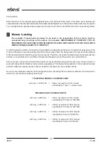
6  MACHINE ADJUSTMENT

In the Table of capacities, supplied with each spray head, look for the spraying capacity per hour obtained (5). Take
note of the adjusting disc number, from 1 to 15, and of the working pressure value.
If the value of spraying capacity per hour (5) does not coincide with those given in the table, make reference to the
closest one. The new value, divided by the worked surface per hour (3) gives the new amount of litres sprayed per
hectare.
POSITION ALL ADJUSTMENT DISCS OF THE MACHINE ON THE NUMBER FOUND AND CARRY OUT
TREATMENT WITH THE CORRESPONDING WORKING PRESSURE GIVEN IN THE TABLE.

7  MIXTURE BATCHING

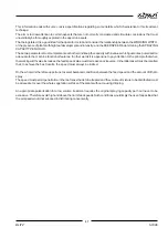
The quantity of agrochemical product to be employed must be calculated based on the surface to be treated.
Independently from the type of equipment or the litres of water employed, each hectar of cultivation always needs
the same quantity of product.
FOR  EACH  HECTARE  OF  CULTIVATION  ONE  MUST  EMPLOY  THE  SAME  QUANTITY  OF  PRODUCT
DISTRIBUTED DURING THE TREATMENTS OF THE PREVIOUS SEASONS, MIXING IT WITH THE VOLUME OF
WATER SELECTED FOR THE TREATMENT.
To rationalize the treatment, remember that "quantity distributed per hectar in the previous seasons" means that
part of product actually distributed over the cultivation. If it refers to treatments made with normal volume systems,
then the dose of agrochemical product per hectare can be reduced.

Содержание BLITZ 45T

Страница 1: ...LOW VOLUME TRAILER SPRAYER INSTRUCTIONSFORUSE ANDMAINTENANCE S p A BLITZ UM55001 ...

Страница 2: ...isfied at the right price Our continuous engagement in R D and in testing our machines allows us to realize products able to offer the best performances a high reliability and a great easiness of use at the same time Our first goal is to get our Customers happy for having met us The Spare parts catalogue of this sprayer sprayhead is available in the restricted area on website www cima it In order ...

Страница 3: ...LOW VOLUME TRAILER SPRAYER 27047 S MARIA DELLA VERSA PV ITALIA Via Sicilia 2 Tel 0385 278223 a s Fax 0385 798184 S p A INSTRUCTIONS FOR USE AND MAINTENANCE Serial No BLITZ ...

Страница 4: ...tion is composed of 66 pages divided in the following manner PAGENO REVISION ISSUEDATE from I to IV 00 March1996 from 1 to 62 00 March1996 REGISTRATIONS OF ADDITIONS AND CHANGES REVISION DESCRIPTION 00 First Edition March 1996 01 02 03 04 05 06 07 08 ...

Страница 5: ...10 4 STRUCTURALANALYSISOFTHEMACHINE 11 4 1 DRAWBAR 12 4 2 SWIVELLINGDRAWBAR OPTIONAL 13 4 3 FAN DRIVE 14 4 4 HYDRAULICCIRCUITCOMPONENTS 15 4 5 TECHNICALDATA 19 4 5 1 Machines dimensions and weights 19 4 5 2 Wheels sizes and working pressure 19 4 5 3 Fan pumpfunctionalcharacteristics 19 4 5 4 Fan technical characteristics 20 5 COUPLINGMODE 21 5 1 TRACTORHOOK UP 21 5 1 1 Sprayerwithstandarddrawbar 2...

Страница 6: ...8 12 2 OPERATIONSINPREPARATIONFORTREATMENT 48 12 3 TREATMENT 49 12 4 ENDOFTREATMENT STORAGE 50 12 4 1 Daily 50 12 4 2 End of seasonal cycle 50 13 LIFTINGANDTRANSPORT 51 14 MAINTENANCEOPERATIONS 52 14 1 LUBRICATION 52 14 2 CLEANINGTHEDELIVERYFILTER 53 14 3 CLEANINGTHESUCTIONFILTER 53 14 4 FANCLEANING 54 14 5 FANBELTSTRETCHER 54 14 6 PUMPBELTSTRETCHER 54 14 7 TABLEOFMAINTENANCEOPERATIONS 55 15 TROUB...

Страница 7: ...e using the sprayer the operator should read and adhere to all of the instructions listed in this manual which are updated through the publication date 1 4 REFERENCE TO REGULATIONS This manual was created in conformity with the instructions contained in Enclosure I of Instruction 89 392 C and subsequent modifications letters b c of point 1 1 2 and point 1 7 4 UNI EN 292 2 1992 point 5 5 1 5 USE OF...

Страница 8: ...nd legible in all its parts In case of loss the owner must immediately ask C I M A S p A for a duplicate If thedecalsoriginallyplacedonthemachineshouldbecomelost damagedorevenpartiallyincomprehensible theymust be replaced without delay Each type of head which can be used with the sprayer is delivered complete with a specific manual for use and maintenance This constitutes an enclosure to this publ...

Страница 9: ...ight inch Micron 1 1000 of millimeter PTO powertake off s seconds 2 3 SAFETY DECALS The machine is provided with decals concerning safety use and maintenance Safety 1 95001 STOPTHEMOTOR ANDTAKETHE KEYOUTOFTHETRACTORCONTROLPANELBEFORE CARRYINGOUTANYMAINTENANCEORREPAIROPERATION Position on the plastic protection guard of the gearbox group 2 95004 DANGER CONTAMINATION DUE TO CONTACT WITH OR INHALATIO...

Страница 10: ... maintenance 12 95052 GREASEEVERY20HOURS FANSHAFTBEARINGS Position on the frame front left part 13 95053 GREASEEVERY50H0URS FANBELTSTRETCHERSUPPORT Position on the frame front left part 14 95054 GREASEEVERY200HOURS 1 FREEWHEEL position on the front part near the PTO protection guard 2 BEARING FOOT position under the adjustment crank 3 WHEEL HUBS position on the hubs 15 95067 OILEVERY50HOURS PUMPBE...

Страница 11: ...9 14 11 1 6 2 19 15 15 additional pump optional UM55005 16 2 4 12 19 13 21 UM55019 9 20 UM55004 18 11 14 16 8 2 17 14 three way tap supplied assembled with the additional pump optional NOTE Thenumberswithasteriskindicatesthe decals to be used with the additional agitation pump 7 UM55003b 10 3 ...

Страница 12: ...47 14 95054 UMAP044 15 95067 UMAP045 16 95057 UMAP065 UMAP060 4 95008 7 95007 UMAP058 UMAP055 5 95015 6 95010 UMAP066 8 95006 UMAP059 11 95059 9 95009 UMAP056 UMAP061 10 95073 UMDD025B Use and maintenance UM55020 95071 21 UM55021 95060 17 95065 95056 19 18 95063 UMDD020 ATTENTION MACHINE NOT APPROVED FOR CIRCULATION ON THE ROAD 95073 ...

Страница 13: ... AS IT HAS BEEN DEVELOPED EXCLUSIVELY FOR DISTRIBUTING INSECTICIDES ON AGRICULTURAL CULTIVATIONS The following general rules must be respected scrupulously always stop the motor before carrying out any operation on the sprayer check that the weight and power of the tractor are compatible with the sprayer to be used before use check the different components of the machine for correct tightness and ...

Страница 14: ...nts to wash areas and or machinery or to utilize the air stream for purposes different from the distribution of agrochemicals 3 4 SAFETY DEVICES All running parts of the machine are adequately protected and indicated by warning decals It is forbidden to use the machine if the protection devices have been removed Before lifting the tank lid or removing the protection devices stop the motor of the t...

Страница 15: ...partially empty should be kept in their original packaging and their labels should always be legible Theinstructionsforstorage useanddisposalwhicharedisplayedontheoriginalpackagingofthe products should always be scrupulously respected 3 5 2 Specific equipment Thepreparationorfillingareamustprovide all the equipment necessary for measuring the exact quantity of water and of the product to be poured...

Страница 16: ... to allow perspiration with side polypropylene coatings It is possible to find disposable tyvek overalls that after use see picture must be disposed of in the same way as the toxic waste Half size mask in neoprene rubber with 1 or 2 filters It is possible to use filters for gas and organic vapors European class A1 combined with filters against powder European class P1 for mists and irritating powd...

Страница 17: ... DISTRIBU TOR CENTRIFUGAL PUMP FRAME PROTECTION BAR CENTRIFUGAL FAN LIQUID LEVEL GAUGE OF THE TANK UMAT001 FILTER ON DELIVERY AXLE COUNTERGUARD LIQUID LEVEL GAUGE OF THE TANK MAIN TANK HANDWASH TANK FILLER SERVICE OPENING Main components of the trailed sprayer ELECTRIC DISTRIBU TOR COCK ELECTRIC DISTRIBUTOR CONTROL BOX UMAP094a PRESSURE GAUGE PRESSURE VALVE PARKING STAND UM55007 ...

Страница 18: ...or the frames up to 1000 lt and 8 16 24 cm on the 1500 2000 lt ones UMAT008 UMAT009 UM55001 12 cm After each adjustment carefully tighten the screws and the nuts involved in the operation 18 cm AXLE The axle shafts inserted in the frame axle and locked by appropriate screws allow to adjust the track width adapting it to the operation requirements The height from the ground is adjustable The offset...

Страница 19: ... PARKING STAND must always be raised when using the machine The drawbar must never be used as parking stand for the machine instead of the bearing foot PROTECTION BAR It is fitted to the machine rear side to protect the distribution devices heads It must be fitted in the most effective position with respect to the work conditions and type of head SUPPORTING BRACKET It is fitted to the drawbar to a...

Страница 20: ...necessary Centrifugal fan 4 3 FAN DRIVE It is placed in the front part of the machinef and protected by a polyethylene shaped guard PTO COUPLING POLY V BELT V BELT UMAP009 AUTOMATIC BELT RENSIONER LOWER PULLEY FREE WHEEL RELEASE PUMP The front release device fitted to the fan shaft allows the running of the centrifugal pump excluding that of the fan An air intake on the housing outside the rim all...

Страница 21: ...ransparent pipe and scale on the tank hydraulic mixture agitator connected to the return pipe T3 ATTENTION P and E circuit parts T pipings 4 4 HYDRAULIC CIRCUIT COMPONENTS DELIVERY Hydraulicconnectiondiagram Hydraulicagitator P1 E8 P8 UM55010 For versions where it is foreseen T4 T3 T2 P4 T1 T3 E7 T5 P9 P9 P7 P6 P5 T3 P2 P3 T6 umap026a UM55009 ...

Страница 22: ... the P2 filter the P3 three ways tap the P4 pump the P5 knob cock and the T3 piping The sprayng is carried out by opening the distributor P7 or E7 b discharge The liquid in the P1 tank reaches the P3 tap coming from the P2 filter with cock and through the T3 piping the P5 cock and the P4 pump The circuit discharge happens when the tap s lever is in b position c filling The P6 piping is fitted to t...

Страница 23: ... nut locks the cover to the filter body Filter capacity 240 lt min Filtering cartridge 50 meshes A dirty cartridge causes a drop in the working pressure The problem is indicated by the manometer The filter is fitted to the delivery and filters only the supply flow to the distribution devices thus remarkably reducing the possibility for cartridge clogging P7 PRESSURE GAUGE In glycerine bath Dial fr...

Страница 24: ...not coupled to the tractor it must be set in the appropriate seat on the frame in the front part of the machine T5 DISTRIBUTION PIPING It connects the distributor P8 E7 with the P9 rotating disk adjustment unit mounted on the distribution devices P9 CALIBRATIO DISK ADJUSTMENT UNIT It selects the necessary deliveries during treatment and is mounted on the distribution devices Two flanges held by tw...

Страница 25: ...weigth kg 966 1204 1444 BLITZ 50T 50T1500 Total width mm 1060 1090 1380 1660 Total heigth mm 1250 1370 1370 1480 Total length mm 3100 3370 3430 4300 No load weigth kg 374 412 450 550 Full load weigth kg 998 1258 1500 2125 BLITZ 55T BLITZ 55TS BLITZ 55TE Total width mm 1530 1660 1720 Total heigth mm 1440 1480 1720 Total length mm 3450 4300 4300 No load weigth kg 494 580 608 Full load weigth kg 1544...

Страница 26: ...00 14000 15500 Air speed m s 188 175 150 170 180 Absorbed power kW 17 24 28 36 43 BLITZ 45T BLITZ 50T BLITZ 50T1500 BLITZ 55T BLITZ 55TS BLITZ 55TE Steel fan YES YES YES YES YES YES Plastic housing YES YES YES YES YES YES 90 elbow union YES YES YES Inside diameter of housing outlet opening mm 175 175 250 250 250 250 PTO shaft 1 3 8 SAE DIN 9611 A YES YES YES YES YES YES Main pulley diameter mm 450...

Страница 27: ...sition the rudder trail eye at the same height as the trail fork by adjusting the bearing foot 9 Start the tractor and insert the trail eye in the fork following the instructions of point 1 10 Stop the tractor Take the keys out of the control panel 11 Lock the hook by means of the safety release pin 12 Completely lift the bearing foot 13 Place the 2 cocks P8 manual distributor or the E8 electric c...

Страница 28: ... at the same height 9 10 By means of the top link set the axis of the 2 PTO s on the same plane 11 Lock the 3 point by tichening the chains of the 3 point lift At the end of the operation the 2 PTO s must be positioned on the same plane 5 2 PTO SHAFT Use drive joints with CE certificate Stop the tractor take the key out of the control panel and make sure that nobody touches the hydraulic controls ...

Страница 29: ...1 Drive joints The 2 halves should be assembled when the 2 PTOs are parallel Prevent the pto from working with angles wider than 15 The operating conditions may also be obtained by adjusting the drawbar height and lenght When turning with the PTO running the steering angle may be 30 only if the hitch point is equidistant from the PTOs At an angle any greater than this it will be necessary to stop ...

Страница 30: ...EAND MAINTENANCEMANUALSUPPLIEDBYTHEPTOSHAFTMANUFACTURER DETERMINING THE LENGTH Follow the same instructions as thE one given in Paragraph 5 2 1 5 3 INSTALLATION OF REMOTE CONTROLS 5 3 1 P8 2 valve manual distributor 1 Fix the fastening bracket onto the tractor within the driver s reach 2 Insert the distributor bayonet support into the fastening bracket 3 ConnecttheT5distributionpipingstothehydraul...

Страница 31: ...he plug into the tractor socket The W1 supply cable is supplied complete with electric socket to be fitted to the tractors which have none or to replace the existing one if it does not match with the plug 4 ConnecttheT5distributionhosingwiththehydrauliccircuitofthedistributiondevice head fittedtothemachine follow the instructions of the use and maintenance manual delivered by the manufacturer Posi...

Страница 32: ...tion device with 600 mm extension T GC P06 50 02T GC P06 50 02 Tobacco cannon multiple disribution device with 90 elbow and 500 mm extension T GC P05 55 01T GC P05 55 01T GC P05 55 01 Rotating group with electric control device T GIR E 175T T GIR E 175T T GIR E 175T T GIR E 250T T GIR E 250T T GIR E 250T 2 fishtail spray head with 3 wide sector T 2V 45T 02 T 2VS 55T 02 T 2VS 55T 02 T 2VS 55T 02 2 ...

Страница 33: ...e additional parts considered standard which modify their position The use and maintenance manual of each distribution device gives the necessary type of elbow union and the assembling instructions UM55003A UM55003 UM55T15I COMPLETE RANGE BLITTZ 45T 50T BLITZ 55T 55TS 55TE 50T1500 Fan outlet opening inside diameter 175 mm inside diameter 250 mm BASIC MODEL OF THE RANGE machine delivered WITH 90 EL...

Страница 34: ...IONAL AGITATION PUMP All indications and instructions can be found in the use and maintenance manual supplied with this optional accessory 7 4 MECHANICAL BLADE AGITATOR All indications and instructions can be found in the use and maintenance manual supplied with this optional accessory 7 2 ROTATING GROUP WITH ELECTRIC CONTROL It is an accessory used to modify the spraying direction It may be used ...

Страница 35: ...situated in the machine front part under the protection guard andcanbereachedthroughtheappropriatemovablecover Releasing the fan for filling operation EXECUTION 1 Bring the atomizer on the filling site 2 Stop the tractor take the key out of the control panel and check that the fan has stopped Remove the P5 P6 P7 adjustment group by taking away the supporting bracket Press thespringpush buttontillt...

Страница 36: ...UT FLUID 6 Start the tractor respecting the safety norms Engage the PTO and keep it at 500 rpm 7 Pour the necessary quantity of insecticide and the possible water used for washing the product packages and the tools used for preparation 8 Finish filling and carefully screw the tank cover 9 Keep on agitating the mixture in the tank and bring the operative unit in the cultivation to be treated ONTREA...

Страница 37: ...WITH FILLING PIPING Before use check for the foot valve good running and seal by pouring some water into the piping THE PUMP MUST NEVER RUN WITHOUT ANY FLUID EXECUTION 1 Release the fan see point 8 1 2 Turn the lever of the 3 ways tap P3 on position c 3 Shut the cocks of the 2 ways distributor a if it is handoperated P8 put them in horizontal position b if it is electric E8 put the release switche...

Страница 38: ...unittothecultivationtobetreated ONTREATMENTSITE 16 Stop the tractor and take the key out of the control panel CHECK THAT THE FAN HAS STOPPED 17 Engage the fan in the gearbox follow the instructions given in point 8 1 pushing the front body instead of pulling it 18 Re fit the movable cover protecting the release 19 Start the tractor Engage the PTO and carry out another agitation keeping the PTO at ...

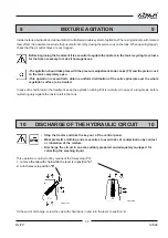
Страница 39: ...e active principle over the whole vegetation surface to be treated In case of a short break in the treatment keep the agitation running till it is re started In case of a long break before re starting duly agitate the mixture left in the tank 10 DISCHARGE OF THE HYDRAULIC CIRCUIT 10 Stop the tractor and take the key out of the control panel Wear protective clothing and accessories to avoid risks o...

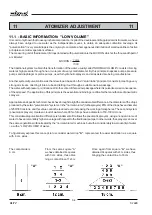
Страница 40: ...houtpressure isintroducedintothecenterofthisnarrowpassagewhereitispulverized asaconsequence oftheairspeed Theapplicationofthisprincipleistheessentialandbindingconditionforthemanufactureofpneumatic sprayers Appropriateandspecifictechnicalcheckshavebroughttolighttheconsiderabledifferenceinthediametersofthedrops producedbythesetwo pulverization systems Inthe normalvolume turbosprayers 85 ofthedropsha...

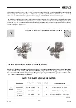
Страница 41: ...sisted the number of drops per cm2 will only be 0 7 1 l ha with Ø 300 microns 0 7 drops per cm2 NORMAL VOLUME WerecalltoyouthattheQUANTITYOFAGROCHEMICALPRODUCTtobedistributedperHECTARE depending on the cultivation to be treated REMAINS UNCHANGED independently from the type of machine employed It can be deduced from the tables printed on the product packages and from the quantity of water used for ...

Страница 42: ...Mixture concentration 4 times or quadruple Wateremployed 1000 lt 1loading LOWVOLUME Treatmentof1hectarewith3Kgofproduct The concentration of the mixture is to be selected depending on the lt ha to be employed Mixture concentrazione 4 times or quadruple UMAPT09I 1 ha MACHINE USED PULVERIZATION SYSTEM PRODUCT EMPLOYED WATER EMPLOYED MIXTURE CONCENTRATION AIR ASSISTED NORMAL VOLUME Kg 3 1000 lt ONCE ...

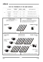
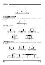
Страница 43: ... the a m distance is 3 mt each row occupies a strip of land 3 mt wide 1 5 mt on one side and 1 5 mt on the other If each passage covers 2 rows corresponding to 2 strips of land the virtual width of treatment will be 6 mt TheVIRTUALWIDTHOFTREATMENTISthereforeOBTAINEDbyMULTIPLYINGTHENUMBEROFROWSTREATED ATEACHPASSAGE BYTHEDISTANCEINMETERSBETWEENTHEROWSOFTHECULTIVATION Thecalculation must of course al...

Страница 44: ...s Itrequirestwopassages for each row 1 ONE ROW Lm D mt 3 The virtual width corresponds to a strip of land as wide as the distance between the rows It requires one passage for eachrow 2 TWO ROWS Lm 2D mt 6 The virtual width corresponds to a strip of land twice as wide as the distance between the rows It requires the passage everyotherrow UMAP081 UMAP082 UMAP083 UMAP084 UMAP085 UMAP086 ...

Страница 45: ...e beginning of the vegetation cycle than those covered during the period of maximum vegetation Feed speed km h This is the speed of the tractor sprayer operative unit when carrying out treatment It must be decided in practice on the field depending on the ground conditions how the cultivation is planted and the typeofsprayeremployed Itisalsoessentialtoselectagearwhichrespectsthefunctionalcharacter...

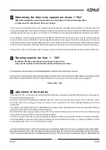
Страница 46: ...sy to determine and you can have it using the two parameters obtained above It is of fundamental importancebecause onlybyknowingtheexactsurfaceworkedperhour itispossibletocalculatethequantityofwater the sprayer must spray in one hour in order to carry out the treatment with the selected litres per hectare In short to state how many hectares of ground can be worked in one hour it is sufficient to u...

Страница 47: ...ally defined with the information given till now BYMULTIPLYINGTHEHECTARESTREATEDPERHOUR ha h BYTHESTATEDLITRESPERHECTARE It ha ONE OBTAINS THE SPRAYING CAPACITY PER HOUR It h according to which the sprayer will be adjusted ha h x It ha It h Adjustment of the machine The knob cock P5 connected to the piping returning to the tank adjusts the pump discharge flow and consequently the treatment working...

Страница 48: ... Therefore theneededquantityofagrochemicalproductper hectare is a value that can be considered constant and always known by those who carry out treatments With our sprayer the product needed for the treatment may be distributed see point 4 with a very reduced volume of waterwithrespecttothetraditionalnormalvolumeapparatuses Thisimpliesthepreparationofconcentratedmixtures and the smaller the quanti...

Страница 49: ...of the cultivation comes only from the coverage technique that to distribute on the vegetation the necessary dose i e 75 of that quantity unavoidably disperses the remaining 25 Therefore of the 3 kg of agrochemical product per hectare mentioned in the example only 2250 gr 75 will actually be distributed on the plants and the remaining 750 gr 25 will be dispersed in the environment A correct use of...

Страница 50: ...ue If the value of spraying capacity per hour 5 does not coincide with those given in the table make reference to the closest one Thenewvalue dividedbytheworkedsurfaceperhour 3 givesthenewamountoflitressprayedper hectare POSITION ALL ADJUSTMENT DISCS OF THE MACHINE ON THE NUMBER FOUND AND CARRY OUT TREATMENTWITHTHECORRESPONDINGWORKINGPRESSUREGIVENINTHETABLE 7 MIXTURE BATCHING The quantity of agroc...

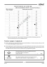
Страница 51: ...r each 100 lt The treatments required the use of 7200 lt of water and 27 kg of agrochemical product Lm If at each passage 2 rows of 2 50 mt distance are covered 1 WORKING the working width to be considered is WIDTH 2 rows x mt 2 50 5 mt Km h 10 After practical operation on the field a feed speed of 5 2 km h 2 FEEDSPEED is stated This value divided by 10 gives a parameter of 0 52 TABLE OF CAPACITIE...

Страница 52: ...FICIENT TO POSITION ALL DISCSONNO 8ANDCARRYOUTTREATMENTWITHAPRES SURE OF 2 5 ATMOSPHERES In case it is decided to carry out the treatment with 250 lt ha then thesprayingcapacityperhour 5 wouldbe650lt 250lt hax2 6ha Assuchvalueisnotlistedinthetableyoumustconsidertheclosest one i e 643It h whichrecommends theadjustmentdiscstobeset on no 10 with a working pressure of 1 5 atmospheres The new capacity ...

Страница 53: ...nctional features In other words it is opportune to pay attention to the principle that when theworkingwidthvalueincreases thefeedspeedvaluemustdecreaseandviceversa Inthelattercaseitmustberecalled that to achieve the best results the speed must always be limited On the whole it is therefore opportune to select balanced conditions between the feed speed and the amount of lt ha to spray Thespeedmust...

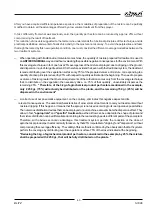
Страница 54: ...for treatment and the volume of water to be employed f Check that a sufficient quantity of product for the whole treatment is available g Carefully read the instructions for the use of the product to check the conditions for use the correct batching and the expiration dates h Calculatethenecessaryparametersforadjustingthemachineanddeterminetheexactquantityofproducttobeused foreachloading See instr...

Страница 55: ...s andenvironmentalpollution m After you have loaded the machine fill the tank for personal cleaning with clean water n Ifnecessary markthefieldorthemachinepassagearea toprovideaguidefortreatmentandtoavoidmissingparts oroverlappinglayers ATTHEENDOFTHEOPERATIONNECESSARYFORTREATMENT THESTORAGE CONSERVATION AREAS MUST BE LEFT IN THE CONDITIONS REQUESTED IN ORDER TO PERFORM THEIR PREVENTIVEANDPROTECTIV...

Страница 56: ...er then spraying the same on the field where treatment was done If necessary repeat this operation c Checktheefficiencyofthedistributiondevice sprayhead andthecleanlinessofthepulverizationpoints diffusers replacing them if they are damaged or in bad condition The cleaning of calibrated holes must not be done with hard or sharpened tools d Putthemachineinaventilatedplace shelteredfromrainandsun the...

Страница 57: ...ible for non observance of these laws Lifting and transport of the sprayer Before carrying out any operation it is essential to check that there are no mixture residues left in the tank 1 Check that the cables or the chains are adequate for the weight to be lifted machine distribution devices accessories 2 Hook the machine up in the supporting points indicated on the frame by decals and check the ...

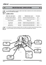
Страница 58: ...4 Freewheel UMAP045 UMAP046 Fan shaft bearings support UMAP044 Wheel hub UMAP047 Fan belt stretcher support UM55001 UMAP044 Bearingfoot UMATT11I Parts to be lubricated action Material to be used Periods Fan shaft bearing support Grease Grease type EP Class NLGI 2 20 h Fan belt tensioner support Grease Grease type EP Class NLGI 2 50 h Pump bearing Lubricate Engine oil 50 h Free wheel Grease Grease ...

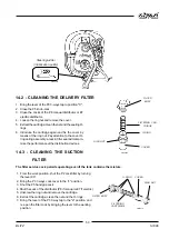
Страница 59: ...ribution devices 14 3 CLEANING THE SUCTION FILTER BODY UMAP044 Steeringrudder 3 lubrication points FILTER BODY O RING COVER RING NUT COVER UMAP050 FILTER The filter service cock permits operating even if the tank contains the mixture RING NUT FILTERING CARTRIDGE UM55016 1 From the work position shut the P2 cock filter by turning the lever 90 2 Bring the P3 3 ways cock lever to the c position 3 Shu...

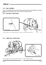
Страница 60: ...ARRIEDOUTATAC I M A AFTER SALESERVICECENTER 14 5 FAN BELT STRETCHER UMAT039 L 4 5 cm UM55001 UMAT020 UM55002 L 9 12 cm L L Check the length L of the spring see picture it must be in tension between 9 and 12 cm 14 6 PUMP BELT STRETCHER Check the length L of the spring see picture it must be in tension between 4 and 5 cm ...

Страница 61: ... YES YES 50 h Wheels bearing GREASE YES YES Bearing foot GREASE YES YES Free wheel GREASE YES YES Rudder GREASE YES YES Couplings and pipings CHECK THEIR INTEGRITY YES YES Clamps and unions CHECK TIGHTENING YES YES SI Suction filter CHECK CLEALINESS YES YES YES Delivery filter CHECK CLEANLINESS YES YES YES Hydraulic circuit and tank WASH YES YES Hydraulic circuit and tank CLEAN AND COMPLETELY EMPT...

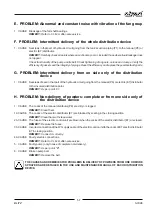
Страница 62: ...ightening of ring nuts and clamps Verify the efficiency of gasket Replace the possible faulty parts 2 CAUSE Leak of seal O ring of the outside pump coupling flanges REMEDY Refer to C I M A after sale service 3 CAUSE Breakage of mechanic seal REMEDY Refer to C I M A after sale service C PROBLEM Hydraulic circuit pressure drop signalled by the manometer 1 CAUSE Delivery or suction filter are dirty R...

Страница 63: ...c E7 distributor to the involved distribution point REMEDY As per point F 1 H PROBLEM Non delivery of powders complete or from one side only of the distribution device 1 CAUSE The cocks of the manual distributor P8 are dirty or clogged REMEDY Clean them 1b CAUSE The cocks of the electric distributor E7 are blocked by scaling in the closing position REMEDY Clean them with clean water 2b CAUSE The f...

Страница 64: ...e Introduce the belt into the pump pulley race and then into the race of the upper pulley behind the release Reset the belt stretcher spring in in the prescribed tension condition Re assemblethefangroupprotectionguard UMAP009 1 ADJUSTMENT GROUP FUSE CARRIER COVER UMAP053 ELECTRIC CONTROL UNIT FUSE Stop the motor and take the ingition key out of the tractor s control panel 1 Unscrew the fuse holdin...

Страница 65: ...7 2 WAY ELECTRIC DISTRIBUTOR ELECTRIC CONTROL UNIT E8 W1 cable W2 cable For the versions where it is foreseen UM55014 DELIVERY PIPING KNOB COCK FOR PRESSURE ADJUSTMENT MANOMETER P7 ROTARY DISC ADJUSTER P9 SUCTION PIPING FILTER P5 T4 DELIVERY FILTER P6 P4 PUMP T1 P2 T2 T3 T1 FILTER Additional agitation PUMP SUPPLY CONNECTOR P3 THREE WAYS COCK Discharge COCK ...

Страница 66: ...ECTIONS YELLOW GREEN PINK BLUE WHITE VIOLET F2 F2 F2 F1 IP SW DPDT RED BLACK BLACK F1 5 A 250 V F2 1 25 A 250 V PREARRANGEMENT IG BROWN WHITE BLUE SERVICE SOCKET SW DPDT SW DPDT I2 I1 ELECTRIC DISTRIBUTOR UMAP073 CONTROL PANEL SW DPDTR ...

Страница 67: ...hat are not normally subjecttowearandthatarefounddefective willbereplacedfreeofcharge exceptfortransportandworkmanshipcosts The guarantee is no longer valid when a The machine is repaired without the permission of the manufacturer or of one of its service centers b Non original spare parts are used c The machine is used for purposes different from its original intended use d The instructions conta...

Страница 68: ...N 294 EN 349 cumple con los requisitos esenciales de Seguridad y de Preservación de la Salud contenidos en la Diractiva CEE 89 392 y sucesivas modifica ciones Para comprobar la Conformidad a la que se refieren las Directivas anteriormente citadas se han consultado la siguientes Normas Armonizadas EN EN 294 EN 349 est conforme aux exigences de Sécurité et de Sauvegarde de la Santé selon la direttiv...

Страница 69: ......

Страница 70: ......

Страница 71: ......

Страница 72: ...27047 S MARIA DELLA VERSA PV ITALIA Via Sicilia 2 Tel 0385 278223 r a Fax 0385 798184 S p A ...

Отзывы: