Chrysler PT Cruiser Скачать руководство пользователя страница 1378

(21) Lower

the

front

suspension

crossmember

using the transmission jack enough to allow the
power steering gear to be removed from the rear of
the crossmember (Fig. 12). When lowering front sus-
pension crossmember, do not let crossmember hang
from lower control arms. The weight should be sup-
ported by the transmission jack.

(22) Remove the roll pin securing the steering col-

umn lower coupling to the power steering gear pinion
shaft using a roll pin punch (Fig. 13). Push the steer-
ing column lower coupling up and off of the power
steering gear pinion shaft.

(23) Release the pinion shaft dash cover seal from

the tabs cast into the power steering gear housing
and remove the seal from the power steering gear
(Fig. 14).

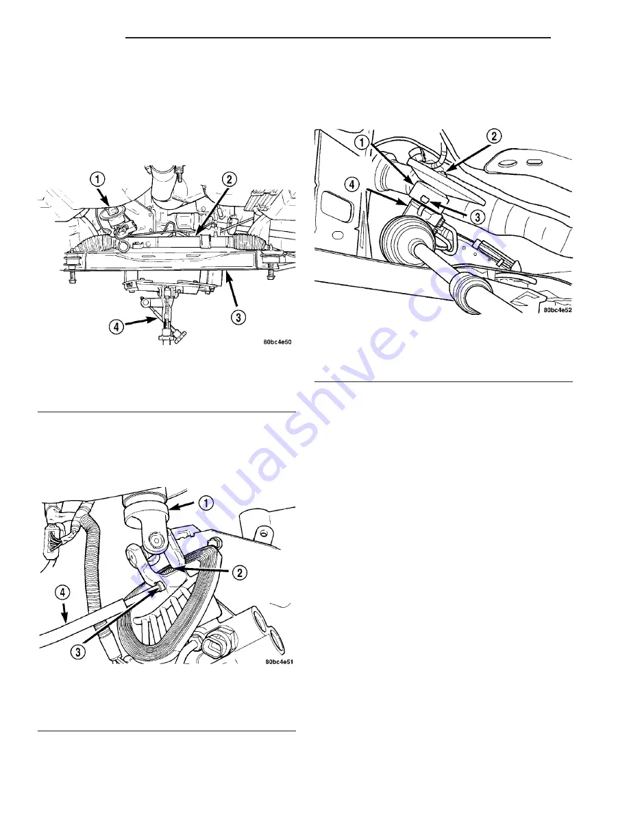
(24) Loosen and remove the four bolts attaching

the power steering gear to the front suspension cross-
member (Fig. 1). Remove the power steering gear
from the front suspension crossmember.

REMOVAL - RHD

Right-Hand-Drive power steering gear is typical of

Left-Hand-Drive. (Refer to 19 - STEERING/GEAR -
REMOVAL - LHD)

INSTALLATION

INSTALLATION

(1) Install the steering gear on the front suspen-

sion crossmember (Fig. 1). Install the four power
steering gear mounting bolts. Tighten the mounting
bolts to a torque of 61 N·m (45 ft. lbs.).

(2) Install the pinion shaft dash cover seal over

the power steering pinion shaft and onto the power
steering gear housing. Align the holes on each side of
the seal with the tabs cast into the power steering
gear housing (Fig. 14).

(3) With

the

steering

column

lower

coupling

pushed partway up through its hole in the dash
panel, match the flat on the inside of the steering
column lower coupling to the flat on the power steer-
ing gear pinion shaft and slide the coupling onto the
top of the pinion shaft. Align the roll pin hole in the
coupling with the groove in the pinion shaft and

Fig. 12 Crossmember Lowered

1 - STEERING COLUMN LOWER COUPLING
2 - POWER STEERING GEAR
3 - FRONT SUSPENSION CROSSMEMBER
4 - TRANSMISSION JACK

Fig. 13 Coupling Roll Pin

1 - STEERING COLUMN LOWER COUPLING
2 - POWER STEERING GEAR PINION SHAFT
3 - ROLL PIN
4 - ROLL PIN PUNCH

Fig. 14 Pinion Shaft Dash Cover Seal

1 - SEAL
2 - PINION SHAFT
3 - TAB
4 - POWER STEERING GEAR

19 - 32

GEAR

PT

GEAR (Continued)

Содержание PT Cruiser

Страница 1: ...l 8J Instrument Cluster 8L Lamps 8M Message Systems 8N Power Systems 8O Restraints 8P Speed Control 8Q Vehicle Theft Security 8R Wipers Washers 8W Wiring 9 Engine 11 Exhaust System and Turbocharger 13...

Страница 2: ......

Страница 3: ...he plenum behind the right side strut tower Fig 2 There are seven lines of information on the body code plate Lines 4 5 6 and 7 are not used to define service information Informa tion reads from left...

Страница 4: ...plate will be fol lowed by END When two plates are required the last code space on the first plate will indicate CTD When a second plate is required the first four spaces of each line will not be use...

Страница 5: ...Fig 3 FASTENER IDENTIFICATION PT INTRODUCTION 3 FASTENER IDENTIFICATION Continued...

Страница 6: ...Fig 4 FASTENER STRENGTH 4 INTRODUCTION PT FASTENER IDENTIFICATION Continued...

Страница 7: ...procedures INTERNATIONAL SYMBOLS DESCRIPTION The graphic symbols illustrated in the following International Control and Display Symbols Chart Fig 5 are used to identify various instrument con trols Th...

Страница 8: ...x 25 4 Millimeters mm mm x 0 03937 Inches Feet x 0 3048 Meters M M x 3 281 Feet Yards x 0 9144 Meters M x 1 0936 Yards mph x 1 6093 Kilometers Hr Km h Km h x 0 6214 mph Feet Sec x 0 3048 Meters Sec M...

Страница 9: ...Fig 6 METRIC CONVERSION CHART PT INTRODUCTION 7 METRIC SYSTEM Continued...

Страница 10: ...N Individual Torque Charts appear within many or the Groups Refer to the Standard Torque Specifica tions Chart for torque references not listed in the individual torque charts Fig 7 Fig 7 TORQUE SPECI...

Страница 11: ...in 1 Built in United States by DiamlerChrysler 3 Built in Mexico by DiamlerChrysler De Mexico 2 Make C Chrysler 3 Vehicle Type 4 Multi purpose Passenger Vehicle Less Side Air Bags 8 Multi purpose Pass...

Страница 12: ...egulation Number Regulation Amendment Number Approval Number VECI LABEL DESCRIPTION All models have a Vehicle Emission Control Infor mation VECI Label Chrysler permanently attaches the label in the en...

Страница 13: ...SKIN CONTACT WITH ENGINE OIL CONTAMINANTS IN USED ENGINE OIL CAUSED BY INTERNAL COMBUSTION CAN BE HAZARDOUS TO YOUR HEALTH THOROUGHLY WASH EXPOSED SKIN WITH SOAP AND WATER DO NOT WASH SKIN WITH GASOL...

Страница 14: ...are a number of engine oils being promoted as either synthetic or semi synthetic If you chose to use such a product use only those oils that meet the American Petroleum Institute API and SAE viscos i...

Страница 15: ...ure water pump seal failure If non HOAT coolant is introduced into the cooling system in an emergency it should be replaced with the specified coolant as soon as possible DESCRIPTION TRANSMISSION FLUI...

Страница 16: ...r vehicle The MMT content of gasoline may not be indicated on the gasoline pump therefore you should ask your gaso line retailer whether or not his her gasoline contains MMT It is even more important...

Страница 17: ...he fluid check fill point locations are located in each applicable service manual section LUBRICATION POINTS DESCRIPTION Lubrication point locations are located in each applicable Sections MAINTENANCE...

Страница 18: ...CHARGED ENGINES 8 000 km 5 000 miles or every other interval shown on Schedule B ALL ENGINES 10 000 km 6 000 miles SCHEDULE B ALL ENGINES Follow schedule B All Engines if you usually operate your vehi...

Страница 19: ...belt and replace as necessary X Miles 39 000 42 000 45 000 48 000 51 000 54 000 Kilometers 62 000 67 000 72 000 77 000 82 000 86 000 Change engine oil and engine oil filter X X X X X X Inspect the br...

Страница 20: ...and replace as necessary X Miles 75 000 78 000 81 000 84 000 87 000 90 000 Kilometers 120 000 125 000 130 000 134 000 139 000 144 000 Change engine oil and engine oil filter X X X X X X Inspect the br...

Страница 21: ...d X Flush and replace the engine coolant at 60 months or 100 000 miles X Inspect the PCV make up air filter Replace as necessary X Inspect and adjust the power steering pump belt tension X Inspect the...

Страница 22: ...or drive belt tension X Miles 42 000 48 000 54 000 60 000 66 000 Kilometers 67 000 77 000 86 000 96 000 106 000 Months 42 48 54 60 66 Change engine oil and engine oil filter X X X X X Inspect the brak...

Страница 23: ...y changed X Replace the PCV make up air filter X Replace power steering belt if necessary X Adjust or replace if necessary generator drive belt X Flush and replace the engine coolant if not done at 60...

Страница 24: ...0 36 42 Change engine oil and engine oil filter X X X X X Inspect the brake linings X Miles 60 000 65 000 70 000 75 000 80 000 85 000 Kilometers 96 000 104 000 112 000 120 000 128 000 136 000 Months 4...

Страница 25: ...ant if not done at 60 months X Replace the PCV make up air filter X Replace the engine timing belt X This maintenance is recommended by the manu facturer to the owner but is not required to maintain t...

Страница 26: ...E DO NOT USE OPEN FLAME NEAR BATTERY REMOVE METALLIC JEWELRY WORN ON HANDS OR WRISTS TO AVOID INJURY BY ACCIDENTAL ARCING OF BATTERY CURRENT WHEN USING A HIGH OUTPUT BOOST ING DEVICE DO NOT ALLOW BATT...

Страница 27: ...ACT THE FUEL TANK OR LINES FUEL LEAK CAN RESULT DO NOT LIFT OR TOW VEHICLE BY FRONT OR REAR BUMPER OR BUMPER ENERGY ABSORBER UNITS DO NOT VENTURE UNDER A LIFTED VEHICLE IF NOT SUP PORTED PROPERLY ON S...

Страница 28: ......

Страница 29: ...KNUCKLE WHEEL BEARING AND HUB 8 ASSEMBLY STEERING KNUCKLE WHEEL BEARING AND HUB 10 INSTALLATION STEERING KNUCKLE 11 LOWER BALL JOINT DIAGNOSIS AND TESTING BALL JOINT 12 LOWER BALL JOINT SEAL BOOT REMO...

Страница 30: ...DAMPENED CLOTH DISPOSE OF CLOTH AND ALL RESIDUE CONTAINING ASBESTOS FIBERS IN AN IMPERMEABLE CONTAINER WITH THE APPROPRIATE LABEL FOLLOW PRACTICES PRESCRIBED BY THE OCCUPATIONAL SAFETY AND HEALTH ADMI...

Страница 31: ...Fig 1 Front Suspension System PT FRONT SUSPENSION 2 3 FRONT SUSPENSION Continued...

Страница 32: ...er Jam Nut 75 55 Tie Rod End to Knuckle Nut 54 40 Wheel Bearing Retainer Plate Bolts 28 21 250 Wheel Mounting Lug Nuts 135 100 SPECIAL TOOLS FRONT SUSPENSION 1 UPPER MOUNT 2 VEHICLE STRUT TOWER 3 OUTE...

Страница 33: ...ench Strut Nut 6864 Remover Installer 6908 2 Remover Installer 8373 Remover C 4150A Press Ball Joint C 4212F Installer Adapter C 4698 2 Remover MB 990799 Remover MB991113 PT FRONT SUSPENSION 2 5 FRONT...

Страница 34: ...ke caliper adapter The knuckle supports the wheel bearing and hub Fig 1 The wheel hub is pressed into a sealed for life wheel bearing that is pressed into the steering knuckle A retainer plate also ho...

Страница 35: ...ball joint stud to the steering knuckle Fig 5 CAUTION The strut assembly to steering knuckle attaching bolts are serrated and must not be turned during removal Hold the bolts stationary in the steerin...

Страница 36: ...WHEEL BEARING AND HUB NOTE The removal and installation of the wheel bearing and hub from the steering knuckle is only to be done with the steering knuckle removed from the vehicle using the following...

Страница 37: ...ner plate to the steering knuckle Fig 11 Remove the bearing retainer plate from the steering knuckle 9 Place the steering knuckle back in the arbor press face down as shown Fig 12 The press sup port b...

Страница 38: ...kle 6 Noting the notch location install the bearing retainer plate on the steering knuckle as shown Fig 11 Install the three bearing retainer mounting bolts Tighten the bearing retainer plate mounting...

Страница 39: ...nuts to a torque of 53 N m 40 ft lbs plus an additional 90 turn after the specified torque is met 5 Place the tie rod heat shield on the steering knuckle arm so that the shield is positioned straight...

Страница 40: ...on the ball joint position the upward lip on the seal boot outside perimeter outward away from the control arm once installed Fig 20 It is there to help shield heat from the sealing boot 2 Place NEW b...

Страница 41: ...ll joints life thus damaging the non vented ball joint seal boot The ball joint used on this vehicle is replaceable and can be serviced as a separate component of the lower control arm OPERATION The l...

Страница 42: ...ners Fig 23 Remove the shield c Remove the pencil strut from the right front corner of the crossmember and body of the vehicle Fig 24 Remove the washer behind the strut from the torque strut bolt d Re...

Страница 43: ...of the Adapter Special Tool 6804 on top of the ball joint as shown Fig 27 4 Using the hydraulic press press the ball joint completely out of the lower control arm into the receiver 5 Remove the tools...

Страница 44: ...not cocked in the bore 2 Position the Installer Special Tool 6758 on a hydraulic press to support the lower control arm Fig 30 Place the control arm on top of Tool 6758 in the upside down position ali...

Страница 45: ...LOWER CONTROL ARM INSTALLATION ASSEMBLY LOWER CONTROL ARM REAR ISOLATOR BUSHING 1 Back the ball joint press C 4212F set screw outward so it does not extend out into the cup area Fig 32 2 Start the bus...

Страница 46: ...ment Fig 23 5 Install a new ball joint stud pinch bolt and nut Fig 22 Tighten the nut to a torque of 95 N m 70 ft lbs 6 Rotate the forward ends of the stabilizer bar into mounting position 7 Clean the...

Страница 47: ...le 4 To remove the cushions from the stabilizer bar peel back each cushion at the slit and roll it off the bar INSPECTION Inspect for broken cracked or distorted stabilizer bar cushions and retainers...

Страница 48: ...ed with a spring meeting the correct load rating for the vehicle and its specific options OPERATION The strut assembly cushions the ride of the vehicle controlling vibration jounce and rebound of the...

Страница 49: ...move the three nuts attaching the upper mount of the strut assembly to the vehicle s strut tower Fig 40 9 Remove the strut assembly from the vehicle 10 For disassembly Refer to 2 SUSPENSION FRONT STRU...

Страница 50: ...OVED 3 Compress the coil spring until all coil spring tension is removed from the upper mount CAUTION Never use impact or high speed tools to remove the strut shaft nut Damage to the strut internal be...

Страница 51: ...igns of deterioration Check the upper mount for cracks and distortion and its retaining studs for any sign of damage Check the upper spring seat and bearing for cracks and distortion Check for binding...

Страница 52: ...pper seat straight out away from the compressor Fig 42 It should line up with the very end of the coil spring coil 9 Install the strut upper mount over the strut shaft and onto the top of the upper sp...

Страница 53: ...t lbs plus an additional 90 turn after the specified torque is met 4 If the vehicle is equipped with Antilock brakes ABS attach the ABS wheel speed sensor to the rear of the strut rearward ear using i...

Страница 54: ...ZER BAR CUSHIONS REMOVAL 47 INSTALLATION 48 STABILIZER BAR LINK REMOVAL 48 INSTALLATION 48 WATTS LINK ASSEMBLY DESCRIPTION 48 OPERATION 49 DIAGNOSIS AND TESTING WATTS LINK ASSEMBLY 49 WATTS BELL CRANK...

Страница 55: ...D BE DONE BY DAMPENING THE BRAKE COMPONENTS WITH A FINE MIST OF WATER THEN WIPING THE BRAKE COMPONENTS CLEAN WITH A DAMPENED CLOTH DISPOSE OF CLOTH AND ALL RESIDUE CONTAINING ASBESTOS FIBERS IN AN IMP...

Страница 56: ...to Body Bolts 54 40 Axle Brake Spindle Bolts 95 70 Axle Parking Brake Cable Bracket Bolts 11 100 Axle Trailing Arm Pivot Bolt 122 90 Hub To Spindle Nut 217 160 DESCRIPTION N m Ft Lbs In Lbs Shock Abso...

Страница 57: ...E LOADED AND LOCKED OUT TO AVOID POSSIBLE INJURY THE LEVER ADJUSTMENT MECHANISM CAN BE LOADED AND LOCKED OUT AS OUTLINED IN THIS PROCEDURE WARNING THE AIRBAG SYSTEM IS A COMPLEX ELECTROMECHANICAL UNIT...

Страница 58: ...he spindle then remove the hub and bearing Fig 5 14 On vehicles equipped with rear disc brakes remove the upper return spring both shoe hold down clips then spread the rear parking brake shoes apart a...

Страница 59: ...g brake cable retainer Fig 10 Fig 6 Rear Disc Brakes 1 DISC BRAKE ADAPTER 2 GUIDE PIN BOLTS 3 HUB AND BEARING 4 BRAKE ROTOR 5 RETAINER CLIP 6 DUST CAP 7 NUT 8 DISC BRAKE CALIPER Fig 7 Parking Brake Sh...

Страница 60: ...in trailing arm 19 On vehicles equipped with antilock brakes remove the bolts securing the wheel speed sensors to the disc brake adapters Fig 14 Remove the sensors from the adapters 20 Remove the fou...

Страница 61: ...ioration of the bushings Make sure the bushings are centered side to side in their bore If a problem exists the bushings must be replaced They can be replaced sep arately from the axle INSTALLATION 1...

Страница 62: ...ber lower mounting bolts can be installed though the axle brackets and shock absorber lower mounting eyes Fig 15 9 Install the washer and nut on the end of each shock absorber lower mounting bolt Tigh...

Страница 63: ...f 95 N m 70 ft lbs 16 On vehicles equipped with antilock brakes install the wheel speed sensors in the disc brake adapters and install the bolts securing them in place Fig 14 Tighten the wheel speed s...

Страница 64: ...mblies on the disc brake adapter Fig 7 22 Install a hub and bearing on each rear spin dle Install a NEW hub and bearing retaining nut Tighten the retaining nuts to a torque of 217 N m 160 ft lbs 23 In...

Страница 65: ...rake 37 Remove the blocks from the tires and wheels 38 Reconnect the battery negative terminal 39 Reinstall the air cleaner cover 40 Place the vehicle on an alignment rack or drive on hoist 41 With th...

Страница 66: ...nstaller and bushing as shown Fig 22 When prop erly installed the screw drive on the special tool will be toward the center of the vehicle Note the curve on the axle trailing arm This curve prevents t...

Страница 67: ...the vehicle at curb height tighten both trailing arm to mounting bracket pivot thru bolts to a torque of 122 N m 90 ft lbs HUB BEARING DESCRIPTION The rear wheel bearing and wheel mounting hub used on...

Страница 68: ...er out of the way using a wire hanger or bungee cord c Remove the brake rotor retaining clips Fig 23 d Remove the brake rotor from the rear hub and bearing 5 Remove the dust cap from the hub and beari...

Страница 69: ...ension Fig 25 The top of each shock absorber is bolted to a bracket attached to the body of the vehicle The bottom of each shock absorber is bolted to the rear axle DIAGNOSIS AND TESTING SHOCK ABSORBE...

Страница 70: ...guide pin bolts then the caliper from the disc brake adapter Fig 27 c Hang the caliper out of the way using a wire hanger or bungee cord d Remove the brake rotor from the rear hub and bearing 5 Remove...

Страница 71: ...dapter and install the bolt securing it in place Fig 29 Tighten the wheel speed sensor mounting bolt to a torque of 12 N m 105 in lbs 5 Align the parking brake cable routing brackets with their mounts...

Страница 72: ...oil type Fig 30 They are mounted straight above the rear axle beam in line with the rear wheels A spring isolator is attached to each end of the coil springs Coil springs come in various heights be su...

Страница 73: ...e sure that the upper coils end near the outboard sides of the vehicle and not 180 degrees of that location 4 Raise the transmission jack guiding the coil springs into the spring mounting brackets on...

Страница 74: ...torque of 149 N m 110 ft lbs 9 Install the rear tire and wheel assemblies Tighten all wheel nuts to a torque of 135 N m 100 ft lbs 10 Lower the vehicle 11 Verify proper vehicle curb height Refer to 2...

Страница 75: ...d in this section 2 Install the stabilizer bar cushions and retain ers on the vehicle as an assembly 3 Hook the lower ends of the cushion retainers in the slot in the back of the axle then rotate the...

Страница 76: ...mbly on the vehicle Tighten the wheel mounting stud nuts in proper sequence until all nuts are torqued to half specifica tion Repeat the tightening sequence this time to full specified torque of 135 N...

Страница 77: ...operate properly Inspect the bell crank for signs of damage Inspect for excessive play in the bearing With the links dis connected rotate the bell crank Any roughness or resistance to rotate may indi...

Страница 78: ...s 6 Verify the words BACK UP can be read on the bell crank from the rear over the top of the axle 7 Lower the vehicle to the ground Fig 37 Rear Suspension 1 ISOLATORS 2 JOUNCE BUMPER 3 SHOCK ABSORBER...

Страница 79: ...he right side of the vehicle to the upper end of the bell crank while the lower link extends from the left side of the vehi cle to the lower end of the bell crank 3 Install the upper or lower link to...

Страница 80: ...heel alignment spec ifications differ On this vehicle the suspension angles that can be adjusted are as follows Front Camber Toe Rear Camber Toe Check the wheel alignment and make all wheel alignment...

Страница 81: ...ar a caster imbalance between the two front wheels may cause the vehicle to lead to the side with the least positive caster CROSS CASTER Cross caster is the difference between left and right caster TO...

Страница 82: ...t necessary to check or adjust front or rear dynamic toe pattern when doing a normal wheel alignment The only time dynamic toe pattern needs to be checked or adjusted is if the frame of the vehi cle h...

Страница 83: ...ective Wheel Bearing 1 Replace Wheel Bearing 2 Incorrect Wheel Alignment 2 Check And Reset Wheel Alignment 3 Worn Tires 3 Replace Tires Front End Growl Or Grinding On Turns 1 Defective Wheel Bearing 1...

Страница 84: ...Tighten Or Replace Ball Joint 6 Worn Or Loose Control Arm Bushing 6 Tighten To Specified Torque Or Replace Control Arm Bushing 7 Loose Crossmember Bolts 7 Tighten Crossmember Bolts To Specified Torqu...

Страница 85: ...ably a vehicle alignment rack The tires are to be inflated to the recommended pressure All tires are to be the same size as stan dard equipment Vehicle height is checked with the fuel tank full of fue...

Страница 86: ...tings Compare the vehicle s current align ment settings to the vehicle specifications for camber caster and toe in Refer to 2 SUSPENSION WHEEL ALIGNMENT SPECIFICATIONS REAR CAMBER AND TOE Rear camber...

Страница 87: ...ntil its tires are not support ing the weight of the vehicle CAUTION The knuckle to strut assembly attaching bolt shanks are serrated and must not be turned during removal Remove the nuts while holdin...

Страница 88: ...traight and the vehicle does not pull or wander SPECIFICATIONS WHEEL ALIGNMENT NOTE All specifications are given in degrees NOTE All wheel alignments are to be set with the vehicle at curb height Refe...

Страница 89: ...irated models equipped with either an automatic or manual trans mission use an unequal length halfshaft system The system incorporates two halfshaft assemblies left and right that consist of an inner...

Страница 90: ...ned into the transaxle side gears The inner tripod joints are retained using a snap ring located in the stub shaft of the tripod joint The outer C V joint has a stub shaft that is splined into the whe...

Страница 91: ...contamination of the joint grease resulting in inadequate lubrication of the joint 3 Noise may also be caused by another compo nent of the vehicle coming in contact with the half shafts CLUNKING NOIS...

Страница 92: ...g removal and installation pro cedures always support both ends of the halfshaft to prevent damage CAUTION The halfshaft when installed acts as a bolt and secures the front hub bearing assembly If veh...

Страница 93: ...ly outward pressure on the joint as you strike the punch with a hammer DO NOT PULL ON INTERCONNECTING SHAFT TO REMOVE AS THE INNER JOINT WILL BECOME SEPARATED 12 Hold inner tripod joint and interconne...

Страница 94: ...ll ensure that the hub bearing cannot loosen 1 Disconnect battery negative cable 2 Place transaxle in gated park 3 Raise vehicle on hoist 4 Remove wheel and tire assembly Fig 11 5 Remove the cotter pi...

Страница 95: ...tward pressure on the joint as you strike the punch with a hammer DO NOT PULL ON INTERCONNECTING SHAFT TO REMOVE AS THE INNER JOINT WILL BECOME SEPARATED 11 Remove halfshaft s Fig 16 Fig 17 Left halfs...

Страница 96: ...ripod joint Lightly lubricate oil seal sealing surface on tripod joint with fresh clean trans mission lubricant 2 Holding halfshaft assembly by tripod joint and interconnecting shaft install tripod jo...

Страница 97: ...ft 2 4L Turbo Models 1 HALFSHAFT LH 2 TRANSAXLE 3 BOLT 4 INTERMEDIATE SHAFT 5 HALFSHAFT RH 6 BOLT 2 Fig 18 Steering Knuckle to C V Joint Sealing Area 1 STEERING KNUCKLE 2 WHEEL BEARING 3 FRONT HUB 4 T...

Страница 98: ...sealing surface on tri pod joint with fresh clean transmission lubricant While holding halfshaft assembly by tripod joint and interconnecting shaft install tripod joint into trans axle as far as poss...

Страница 99: ...26 8 Install spring washer nut lock and cotter pin Fig 26 9 Install front wheel and tire assembly Install front wheel lug nuts Fig 27 and tighten to 128 N m 100 ft lbs Fig 23 Steering Knuckle to C V J...

Страница 100: ...ESCRIPTION N m Ft Lbs In Lbs Bolt Intermediate Shaft Bearing to Bracket 28 21 Nut Driveshaft to Hub Bearing 244 180 Nut Knuckle to Ball Joint Bolt 95 70 Nut Wheel to Hub 128 95 SPECIAL TOOLS HALFSHAFT...

Страница 101: ...housing and slide it down the interconnecting shaft CAUTION When removing the spider joint from the tripod joint housing hold the rollers in place on the spider trunions to prevent the rollers and ne...

Страница 102: ...shaft Fig 33 Spider assembly must be installed on interconnecting shaft far enough to fully install spider retaining snap ring If spider assembly will not fully install on interconnecting shaft by han...

Страница 103: ...lowing positioning procedure determines the correct air pressure inside the inner tripod joint assembly prior to clamping the sealing boot to inner tripod joint housing If this procedure is not done p...

Страница 104: ...ubber insert and tripod hous ing and not the hard plastic sealing boot and soft rubber insert 10 With trim stick inserted between sealing boot and tripod joint housing position inner tripod joint on h...

Страница 105: ...44 Squeeze tool together until top band of clamp is latched behind the two tabs on lower band of clamp Fig 45 13 Install the halfshaft requiring boot replace ment back on the vehicle Refer to 3 DIFFE...

Страница 106: ...ply hit the end of the C V joint housing to dis lodge housing from internal circlip on interconnecting shaft Fig 47 Then slide outer C V joint off end of interconnecting shaft joint may have to be tap...

Страница 107: ...embly is seated against circlip on interconnecting shaft Fig 51 5 Distribute 1 2 the amount of grease provided in seal boot service package DO NOT USE ANY OTHER TYPE OF GREASE into outer C V joint ass...

Страница 108: ...E HALF SHAFT INSTALLATION Fig 52 Crimping Tool Installed on Sealing Boot Clamp 1 SPECIAL TOOL C 4975A 2 INTERCONNECTING SHAFT 3 CLAMP 4 SEALING BOOT Fig 53 Sealing Boot Retaining Clamp Installed 1 CLA...

Страница 109: ...S FRONT REMOVAL 15 CLEANING DISC BRAKE SHOES 16 INSPECTION DISC BRAKE SHOES 16 INSTALLATION 16 BRAKE PADS SHOES REAR DISC REMOVAL 17 CLEANING DISC BRAKE SHOES 18 INSPECTION DISC BRAKE SHOES 19 INSTALL...

Страница 110: ...R DESCRIPTION 52 DIAGNOSIS AND TESTING BRAKE ROTOR 52 STANDARD PROCEDURE BRAKE ROTOR MACHINING 55 REMOVAL REMOVAL FRONT BRAKE ROTOR 56 REMOVAL REAR BRAKE ROTOR 56 INSTALLATION INSTALLATION FRONT BRAKE...

Страница 111: ...ERS FROM PRODUCTION OR AFTERMARKET BRAKE LININGS BREATHING EXCESSIVE CONCENTRATIONS OF ASBESTOS FIBERS CAN CAUSE SERIOUS BODILY HARM EXERCISE CARE WHEN SERVICING BRAKE PARTS DO NOT SAND OR GRIND BRAKE...

Страница 112: ...ssing abutment shims 3 Replace missing abutment shims DISC BRAKE SQUEAK AT LOW SPEED WHILE APPLYING LIGHT BRAKE PEDAL EFFORT 1 Brake shoe linings 1 Replace brake shoes DRUM BRAKE CHIRP 1 Lack of lubri...

Страница 113: ...ear brake shoes Refer to Brake Pads Shoes Drum Brake 4 Obstruction inside the center console preventing full return of the parking brake cables 4 Remove console and remove obstruction BRAKES GRAB 1 Co...

Страница 114: ...ter not allowing pedal to return completely 3 Replace power brake booster VEHICLE PULLS TO RIGHT OR LEFT ON BRAKING 1 Frozen brake caliper piston 1 Replace frozen piston or caliper Bleed brakes 2 Cont...

Страница 115: ...uid level in the master cylinder reservoir to make sure it does not go dry 7 Check the brake pedal travel If pedal travel is excessive or has not been improved some air may still be trapped in the sys...

Страница 116: ...e Fitting Type SAE 45 Inverted Flare Inlet Port Threads Both 7 16 in 24 Outlet Port Threads Left Front and Left Rear 3 8 in 24 ACTUATION Outlet Port Threads Right Front and Right Rear 7 16 in 24 PROPO...

Страница 117: ...ke Pressure Bleeder 6921 Adapters Brake Pressure 8187 Tubes Master Cylinder Bleed 8358 Adapter Brake Pressure 8644 Dial Indicator C 3339 Gauge Set C 4007 A Handle Universal C 4171 Installer Dust Boot...

Страница 118: ...servoir locking it in place Fig 4 2 Connect the brake fluid level switch wiring connector Fig 3 HYDRAULIC MECHANICAL DESCRIPTION DESCRIPTION DISC BRAKES FRONT Each front disc brake assembly consists o...

Страница 119: ...ition the brake shoes and caliper There are two brake shoes sometimes referred to as pads per disc brake One shoe is placed on each side of the brake rotor Fig 10 Two abutment shims upper and lower ri...

Страница 120: ...and adapters to accommodate that additional width The BR4 calipers and rotors can be easily identified Each BR4 brake caliper is marked Turbo while each rotor has a recessed machined area near the hu...

Страница 121: ...uipped with rear disc brakes have a small duo servo drum brake mounted to the caliper adapter This is part of the parking brake system Refer to 5 BRAKES PARKING BRAKE DESCRIPTION This vehicle has an o...

Страница 122: ...the rear adjust ment slot in each brake support plate Fig 15 Rear Brake Rotor Comparison 1 BRT BRAKE ROTOR 2 STANDARD ROTOR THICKNESS 8 75 9 25 MM 3 PERFORMANCE ROTOR THICKNESS 11 75 12 25 MM 4 BR4 P...

Страница 123: ...e vehicle s underbody to the brake at each wheel allowing for movement of the vehicle s suspension INSPECTION BRAKE TUBES AND HOSES Flexible rubber hose is used at both front and rear brakes Inspectio...

Страница 124: ...l thickness should be mea sured at its thinnest point For front disc brake shoes when a set of brake shoes are worn to a thickness of approximately 7 95 mm 5 16 inch they should be replaced For rear d...

Страница 125: ...tire and wheel assemblies from vehicle NOTE Perform Step 3 through Step 7 on each side of the vehicle to complete shoe set removal NOTE In some cases it may be necessary to retract the caliper piston...

Страница 126: ...SERVICING BRAKE PARTS DO NOT SAND OR GRIND BRAKE LINING UNLESS EQUIPMENT USED IS DESIGNED TO CON TAIN THE DUST RESIDUE DO NOT CLEAN BRAKE PARTS WITH COMPRESSED AIR OR BY DRY BRUSHING CLEANING SHOULD B...

Страница 127: ...l the inboard brake shoe into the caliper piston by firmly pressing the shoe in with the thumbs Fig 24 Be sure the inboard brake shoe is positioned squarely against the face of the caliper piston 3 Sl...

Страница 128: ...te Fig 28 Fig 25 Drum Brakes 1 WHEEL CYLINDER 2 SEAL 3 SUPPORT PLATE 4 BRAKE SHOES 5 RETAINER CLIP 6 DUST CAP 7 NUT 8 DRUM 9 HUB AND BEARING Fig 26 Automatic Adjustment Lever Spring 1 ADJUSTMENT LEVER...

Страница 129: ...ING THE BRAKE COMPONENTS CLEAN WITH A DAMPENED CLOTH DISPOSE OF CLOTH AND ALL RESIDUE CONTAIN ING ASBESTOS FIBERS IN AN IMPERMEABLE CONTAINER WITH THE APPROPRIATE LABEL FOL LOW PRACTICES PRESCRIBED BY...

Страница 130: ...nstallation on the vehicle 3 Install the pre assembled brake shoes auto matic adjuster screw and upper return spring on the brake support plate Fig 31 4 Install the wave washer on the pin of park brak...

Страница 131: ...6 Using a brake shoe gauge Special Tool C 3919 or equivalent measure the inside diameter of the brake drum Fig 36 Tighten the gauge set screw at this measurement 7 Place the other side of the brake sh...

Страница 132: ...lt connecting the brake hose to the brake caliper Fig 39 There are two washers one on each side of the flex hose fitting that will come off with the banjo bolt Discard the washers 5 Remove the two bra...

Страница 133: ...OR GRIND BRAKE LINING UNLESS EQUIPMENT USED IS DESIGNED TO CON TAIN THE DUST RESIDUE DO NOT CLEAN BRAKE PARTS WITH COMPRESSED AIR OR BY DRY BRUSHING CLEANING SHOULD BE DONE BY DAMPENING THE BRAKE COM...

Страница 134: ...r to 5 BRAKES HY DRAULIC MECHANICAL DISC BRAKE CALIPER INSTALLATION INSTALLATION CAUTION When installing new brake components be sure to use correct parts Parts designed for BR4 Performance Brake Syst...

Страница 135: ...the lines are discon nected 2 Raise the vehicle Refer to LUBRICATION MAINTENANCE HOISTING STANDARD PROCE DURE 3 Remove the rear tire and wheel assembly 4 Remove the banjo bolt connecting the brake ho...

Страница 136: ...brake caliper clean and inspect it Refer to 5 BRAKES HYDRAULIC ME CHANICAL DISC BRAKE CALIPERS INSPEC TION CALIPER PISTON REMOVAL WARNING UNDER NO CONDITION SHOULD HIGH PRESSURE AIR EVER BE USED TO RE...

Страница 137: ...e burrs on the seal groove edges 3 Using a soft tool such as a plastic trim stick work the piston seal out of its groove in caliper pis ton bore Fig 52 Discard the old seal 4 Clean the piston bore and...

Страница 138: ...ING OF DUST OR DEBRIS THAT MAY CONTAIN ASBESTOS FIBERS To clean or flush the internal passages of the brake caliper use fresh brake fluid or Mopart Non Chlori nated Brake Parts Cleaner Never use gasol...

Страница 139: ...guide pin sleeve into one end of bushing until the seal area of bushing is past the seal groove in the sleeve Fig 57 Fig 54 Folded Caliper Guide Pin Bushing 1 CALIPER GUIDE PIN BUSHING Fig 55 Installi...

Страница 140: ...The seal should be started at one area of the groove and gently worked around and into the groove Fig 59 using only your clean fingers to seat it 2 Coat the new piston boot with clean brake fluid lea...

Страница 141: ...e caliper and brake shoes over the brake rotor and catch the caliper s bottom edge behind the caliper slide abutment Fig 48 Rotate the top of the caliper into mounting position on the adapter CAUTION...

Страница 142: ...e adapter s con tour Fig 63 4 Place the brake shoes in the abutment shims clipped into the disc brake caliper adapter as shown Fig 63 Place the shoe with the wear indicator attached on the inboard sid...

Страница 143: ...Fig 64 5 Install the tire and wheel assembly Tighten the wheel mounting nuts to a torque of 135 N m 100 ft lbs 6 Lower the vehicle 7 Pump the brake pedal several times before moving the vehicle to set...

Страница 144: ...the brake drum Fig 67 NOTE If the drum does not come off further brake clearance can be obtained by backing off the brake automatic adjuster screw Remove the rubber plug from the top of brake support...

Страница 145: ...oir SPECIFICATIONS BRAKE FLUID The brake fluid used in this vehicle must conform to DOT 3 specifications and SAE J1703 standards No other type of brake fluid is recommended or approved for usage in th...

Страница 146: ...th seats for hydraulic brake tube connections The master cylinder has the brake fluid reservoir mounted on top of it which gravity feeds brake fluid to the master cylinder when it is required The res...

Страница 147: ...efore proceeding Refer to 5 BRAKES WARNING Refer to 5 BRAKES CAUTION CAUTION The vacuum in the power brake booster must be pumped down before removing the master cylinder to prevent the booster from s...

Страница 148: ...over aside 3 Remove the air cleaner housing by pulling straight up 4 Disconnect the negative ground cable from the battery and isolate the cable 5 Unlatch the power distribution center lift it up and...

Страница 149: ...uds until it contacts the face of the booster 4 Install the two master cylinder mounting nuts and tighten each to a torque of 18 N m 160 in lbs 5 Connect the two brake tubes to the master cyl inder pr...

Страница 150: ...nnector 7 Install the brake booster vacuum supply hose 8 Install the air cleaner housing 9 Reinstall the air cleaner cover two clips 10 Fill the master cylinder to the proper level Refer to 5 BRAKES H...

Страница 151: ...of 34 N m 300 in lbs 10 Install the power brake booster input rod on the pin mounted on the side of the brake pedal Install a new retaining clip on the end of the pin Fig 77 Do not reuse the old clip...

Страница 152: ...removed stopping short of removing the shaft from the clutch pedal 10 Slide the brake pedal out of its bracket and remove it from the vehicle 11 The bushings can be removed from the pedal by sliding...

Страница 153: ...rify they are oper ating properly and not staying on when the pedal is in the released position 13 Road test the vehicle to ensure proper opera tion of the brakes and speed control if equipped POWER B...

Страница 154: ...eplaced If the vacuum supply is below 12 inches continue on with this BASIC TEST 6 Shut off the engine 7 Connect the vacuum gauge to the vacuum ref erence port on the engine intake manifold 8 Start th...

Страница 155: ...hicle is equipped with ABS remove the three bolts securing the ICU mounting bracket to the frame rail Fig 85 8 Disconnect the vacuum hoses from the check valve on the power brake booster Fig 86 but do...

Страница 156: ...ake pedal pin Remove the clip CAUTION Discard the used retaining clip it is not to be reused Replace the clip with a new one on reassembly 11 Remove the four nuts attaching the power brake booster to...

Страница 157: ...Install a new retaining clip Do not use the old clip CAUTION Do not reuse the original brake lamp switch The switch can only be adjusted once That is during initial installation of the switch If the...

Страница 158: ...ed The in line proportioning valves used on this vehi cle require special pressure fittings to test the pro portioning valves for proper proportioning valve function The pressure fittings are installe...

Страница 159: ...10 Once inlet pressure has been achieved check the pressure reading on the proportioning valve out let gauge If the proportioning valve outlet pressure does not agree with value shown in the table rep...

Страница 160: ...STANDARD PROCEDURE 6 Road test the vehicle to ensure proper opera tion of the brakes ROTOR DESCRIPTION There are two different size rotors available depending on brake application Vehicles with the br...

Страница 161: ...ness at the center of the brake shoe contact surface Replace the rotor if it is worn below minimum thickness or if machining the rotor will cause its thickness to fall below specifications CAUTION Do...

Страница 162: ...l SP 1910 on steering arm The dial indicator plunger should contact braking surface of rotor approximately 25 mm 1 inch from edge of rotor Fig 99 Check lat eral runout on both sides of the rotor marki...

Страница 163: ...stud two studs apart from the original stud Fig 102 Tighten nuts in the proper sequence and torque to specifications Recheck brake rotor runout to see if the runout is now within specifications Refer...

Страница 164: ...e possibility of a tapered or uneven cut When refacing a rotor the required TIR Total Indicator Reading and thickness variation limits MUST BE MAINTAINED Extreme care in the oper ation of rotor turnin...

Страница 165: ...the vehicle to set the shoes to the brake rotor 7 Road test the vehicle and make several stops to seat the brake shoes to the rotor INSTALLATION REAR BRAKE ROTOR CAUTION When installing new brake comp...

Страница 166: ...PLATE DRUM BRAKES REMOVAL NOTE Before proceeding Refer to 5 BRAKES WARNING Refer to 5 BRAKES CAUTION 1 Using a brake pedal holding tool as shown Fig 106 depress the brake pedal past its first one inc...

Страница 167: ...r before installation NOTE When installing wheel cylinder on brake sup port plate be sure it is positioned squarely hori zontal to the brake support plate 2 Install the wheel cylinder onto brake suppo...

Страница 168: ...ke pedal past its first one inch of travel and hold it in this position Fig 110 This will isolate the master cylinder from the brake hydraulic system and will not allow the brake fluid to drain out of...

Страница 169: ...res sively tighten the wheel mounting nuts to a torque of 135 N m 100 ft lbs 8 Lower the vehicle 9 Remove the brake pedal holder 10 Bleed the wheel cylinder as necessary Refer to 5 BRAKES STANDARD PRO...

Страница 170: ...lever auto adjust mechanism must be reloaded and locked out before service can be per formed STANDARD PROCEDURE PARKING BRAKE AUTOMATIC ADJUSTER LOCKOUT WARNING THE AUTOMATIC ADJUSTING FEATURE OF THIS...

Страница 171: ...the parking brake lever to its released full OFF position 6 Check the rear wheels of the vehicle They should rotate freely without dragging with the lever in its released full OFF position 7 Install...

Страница 172: ...117 This will lock the parking brake automatic adjustment mechanism in place and take tension off the parking brake cables Slowly release the output cable There should now be slack in the cables 12 Re...

Страница 173: ...an assembly from the disc brake adapter Fig 121 23 To remove the rear parking brake cable from the brake support plate on vehicles equipped with rear drum brakes Remove the parking brake cable from th...

Страница 174: ...tainer Fig 126 Fig 123 Actuating Spring 1 BRAKE SHOE ADJUSTMENT LEVER 2 ADJUSTMENT LEVER ACTUATING SPRING 3 PARK BRAKE CABLE Fig 124 Parking Brake Cable Removal 1 PARK BRAKE CABLE 2 1 288 WRENCH 3 REA...

Страница 175: ...5 On vehicles equipped with rear drum brakes Install the parking brake cable on the parking brake cable actuating lever Fig 122 Install the actuating spring to the brake shoe and the brake adjustment...

Страница 176: ...G SYSTEM IS A COMPLEX ELECTROMECHANICAL UNIT BEFORE ATTEMPT ING TO SERVICE ANY COMPONENT NEAR THE OCCUPANT RESTRAINT CONTROLLER ORC FIRST DISCONNECT AND ISOLATE THE BATTERY NEGATIVE CABLE ALLOW THE SY...

Страница 177: ...park ing brake lever pin punch drill bit or locking pin if a new mechanism has been installed Fig 128 then quickly remove it from the parking brake lever mech anism This will allow the park brake lev...

Страница 178: ...ear brake shoe and upper return spring Fig 134 13 Remove the front brake shoe hold down clip Fig 135 Remove the front brake shoe assembly INSTALLATION NOTE Perform Step 1 through Step 12 on each side...

Страница 179: ...SC BRAKE CALIPER INSTALLATION 12 Install the tire and wheel assembly Tighten the wheel mounting nuts to a torque of 135 N m 100 ft lbs 13 Adjust the parking brake shoes as necessary Refer to 5 BRAKES...

Страница 180: ...ce is now properly set Insert a medium size screwdriver through adjustment hole in the right backing plate Position the screwdriver against the star wheel on the park ing brake shoe adjuster Using the...

Страница 181: ...and the on car service procedures for the Mark 20e Antilock Brake System ABS and Mark 20e Antilock Brake System with traction con trol All vehicles equipped with ABS use electronic vari able brake pro...

Страница 182: ...t any wheel from locking Each wheel circuit is designed with a set of electric solenoids to allow modulation although for vehicle stability both rear wheel solenoids receive the same electrical signal...

Страница 183: ...l to wheel speed sensor air gap or a damaged speed sensor head face Give special attention to these components when diagnosing a vehicle exhibiting premature ABS cycling After diagnosing the defective...

Страница 184: ...CAUTION This vehicle utilizes active wheel speed sensors Do not apply voltage to wheel speed sen sors at any time CAUTION Use only factory wiring harnesses Do not cut or splice wiring to the brake ci...

Страница 185: ...illuminate so the MIC turns on the red BRAKE warning indicator by default If the amber ABS warning indicator is on road test the vehicle as described below While only the amber ABS warning indicator i...

Страница 186: ...ION The Mark 20e system uses two wire wheel speed sensors known as active wheel speed sensors The sensors use an electronic principle known as magne toresistive to help increase performance and durabi...

Страница 187: ...ction 3 If the sensor being removed is a left front unclip the speed sensor cable from the brake tube on the inside of and under the frame rail Fig 6 Fig 3 Left Front Wheel Speed Sensor Heat Shield No...

Страница 188: ...r cable grom met onto the retaining bracket attached to the brake hose on the outside of the frame rail 4 Loop the wheel speed sensor cable around the bottom of the frame rail and connect it to the wi...

Страница 189: ...xi mately 1 6 volts and 14 mA The CAB measures the amperage of the digital signal for each wheel The resulting signal is interpreted by the ABS CAB as the wheel speed REMOVAL NOTE Before proceeding Re...

Страница 190: ...efer to 5 BRAKES ABS ELECTRICAL REAR WHEEL SPEED SENSOR DESCRIPTION OPERATION The tone wheel is used in conjunction with the wheel speed sensors Refer to 5 BRAKES ABS ELECTRICAL FRONT WHEEL SPEED SENS...

Страница 191: ...C CONTROL UNIT DESCRIPTION HYDRAULIC CONTROL UNIT HCU The hydraulic control unit HCU is mounted to the CAB as part of the ICU Fig 19 The HCU con trols the flow of brake fluid to the brakes using a ser...

Страница 192: ...n these pistons are used to purge fluid from the accumulators back into the master cylinder circuits When the antilock stop is complete the pump motor drains the accumu lators The pump motor is also u...

Страница 193: ...VALVE 2 PUMP PISTON 3 PUMP MOTOR OFF 4 LOW PRESSURE ACCUMULATOR 5 NORMALLY CLOSED VALVE OFF 6 TO RIGHT FRONT WHEEL 7 NORMALLY OPEN VALVE OFF 8 MASTER CYLINDER PRESSURE 9 FROM MASTER CYLINDER 10 NOISE...

Страница 194: ...the brake fluid from the low pressure accumulators is returned to the master cylinder circuits The brake fluid is routed to either the master cylinder or the wheel brake depending on the posi tion of...

Страница 195: ...the brakes and stop the vehicle The hydraulic shuttle valve closes with every brake pedal application so pressure is not created at the inlet to the pump motor Fig 16 ABS With Traction Control Normal...

Страница 196: ...ulate build decay the brake hydraulic pressure as required The pump motor is switched on so that the brake fluid from the low pressure accumulators is returned to the master cylinder circuits The brak...

Страница 197: ...ylinder at a fixed pressure setting The normally open and normally closed valves modulate build decay the brake pressure as required to the spinning wheel Fig 18 Traction Control Hydraulic Circuit 1 O...

Страница 198: ...tle valves valve block fluid accumula tors a pump and an electric pump motor The replaceable components of the ICU are the HCU and the CAB No attempt should be made to service any components of the HC...

Страница 199: ...master cylinder 9 Disconnect and remove the primary and sec ondary brake tubes coming from the master cylinder at the ICU hydraulic control unit HCU Fig 22 10 Clean the area around where the master cy...

Страница 200: ...mounting bracket 2 Install the 3 bolts attaching the ICU to the mounting bracket Fig 23 Tighten the 3 mounting bolts to a torque of 11 N m 97 in lbs CAUTION Before installing the 24 way connector in t...

Страница 201: ...forward most port on the HCU with the small end going toward the master cylinder secondary port 8 Install the primary and secondary brake tubes from the master cylinder onto the HCU Fig 22 Do not com...

Страница 202: ......

Страница 203: ...13 DIAGNOSIS AND TESTING CLUTCH INTERLOCK UPSTOP SWITCH 13 REMOVAL REMOVAL LHD 16 REMOVAL RHD 17 INSTALLATION INSTALLATION LHD 17 INSTALLATION RHD 18 CLUTCH RELEASE BEARING DESCRIPTION 18 OPERATION 1...

Страница 204: ...in the clutch hydraulic system is brake fluid conforming to DOT 3 specifica tions and J1703 standards No other type of fluid is recommended or approved for use in the clutch hydraulic system use only...

Страница 205: ...h all gear ranges and observe clutch action If chatter grab slip or improper release is experienced remove and inspect the clutch components If the problem is noise or hard shifting further diagnosis...

Страница 206: ...Inspect clutch assembly Concentric Slave Cylinder leaking hydraulic fluid Replace Concentric Slave Cylinder CSC CLUTCH IS RUNNING PARTIALLY DISENGAGED Release bearing sticking or binding does not retu...

Страница 207: ...L NOT DISENGAGE PROPERLY Disc bent distorted during transaxle installation Replace clutch assembly Clutch cover diaphragm spring damaged during transaxle installation Replace clutch assembly Release l...

Страница 208: ...eel causing excessive runout Use new bolts when mounting drive plate to crank shaft Tighten drive plate bolts to specified torque only Over tightening can distort the drive plate hub causing excessive...

Страница 209: ...rged If several attempts at purging air from the system are unsuccessful replace both the clutch mas ter cylinder and slave cylinder assemblies 8 Raise vehicle 9 Lower vehicle 10 Top off clutch master...

Страница 210: ...and sprayed around inside the clutch bellhousing by the rotating flywheel contaminating the flywheel disc and pressure plate resulting in poor clutch engagement 4 Using suitable socket wrench loosen...

Страница 211: ...s 24 215 Driveplate to Crankshaft Bolts 95 70 Flywheel to Crankshaft Bolts 95 70 Master Cylinder Pushrod Adj Screw LHD Models 6 55 Modular Clutch to Drive Plate Bolts 88 65 Master Cylinder Mounting Nu...

Страница 212: ...el bolts Remove pressure plate and clutch disc Fig 7 4 Remove eight 8 flywheel to crankshaft bolts and remove flywheel Fig 8 5 Inspect release lever and bearing Fig 9 Replace as necessary Refer to 6 C...

Страница 213: ...of debris oil grease etc Position the flywheel onto the engine crankshaft Fig 8 4 Install and torque the flywheel to crankshaft bolts to 95 N m 70 ft lbs 5 Apply a very light coating of grease to the...

Страница 214: ...to the flywheel Make sure the side marked FLYWHEEL SIDE faces the flywheel Fig 10 7 Install the clutch pressure plate to the flywheel and clutch disc Fig 10 Finger tighten the six 6 pressure plate to...

Страница 215: ...itch is closed allowing speed control operation When the clutch pedal is depressed the upstop switch opens and signals the PCM to cancel speed control opera tion and enter a modified engine calibratio...

Страница 216: ...make sure the clutch pedal lever contacts and fully closes the switch for LHD applications Electrical Test 1 Move ignition key to the OFF LOCK position and remove key 2 Set park brake 3 Disconnect the...

Страница 217: ...5 Depress the clutch pedal at least 33 mm 1 30 in check for continuity between terminals 1 2 There should be no continuity between the terminals open circuit 6 If ohmmeter readings do not fall within...

Страница 218: ...Disengage rod from pedal Fig 21 6 Remove two pedal assembly bracket to instru ment panel nuts Fig 22 7 Remove four brake booster pedal bracket to dash panel nuts Fig 22 8 From under the hood pull bra...

Страница 219: ...vehicle INSTALLATION INSTALLATION LHD NOTE Proper switch harness routing is critical to switch durability Note the harness routing and location of fasteners intended to keep wires from contacting peda...

Страница 220: ...witch The master cylinder push rod must be snapped into the clutch interlock upstop switch along the smaller diameter of the push rod between the snap ring and the transition to the larger diameter CA...

Страница 221: ...ff the lever This may damage the spring clip on the lever 3 As a unit remove the lever from the bearing thrust plate Be careful not to damage retention tabs on bearing 4 Examine the condition of the b...

Страница 222: ...o 6 CLUTCH MODULAR CLUTCH DESCRIPTION The DMF consists of two decoupled masses primary and secondary mass which are connected via a spring damping system Fig 30 The primary flywheel side is bolted to...

Страница 223: ...iced as an assembly only and should never be disassem bled REMOVAL 1 Remove transaxle Refer to 21 TRANSMIS SION TRANSAXLE MANUAL REMOVAL 2 Remove clutch pressure plate and disc Refer to 6 CLUTCH CLUTC...

Страница 224: ...depressed the push rod moves the piston to produce pressure in the cylinder This pressure moves fluid through the sys tem to the slave cylinder which in turn operates the release lever and bearing di...

Страница 225: ...ave cylinder from transaxle Fig 38 Fig 39 Fig 35 Air Cleaner Assembly Removal Installation Typical 1 AIR CLEANER ASSEMBLY Fig 36 Disconnect Hydraulic Circuit Using Tool 6638A 1 QUICK CONNECT FITTING 2...

Страница 226: ...clutch master cylinder reservoir Fig 43 14 Disconnect clutch master cylinder pushrod from clutch pedal Inspect retainer bushing and replace if damaged in any way 15 Remove two clutch master cylinder...

Страница 227: ...n Fig 43 and carefully route hydraulic pipe into posi tion as removed 2 Install clutch master cylinder reservoir Fig 43 3 Install and torque two clutch master cylinder to dash panel retaining nuts Fig...

Страница 228: ...tube Fig 45 1 6 2 0 2 4L Non Turbo equipped models have a master cylinder which incorporates a slave cylinder as well OPERATION The clutch master cylinder Fig 46 Fig 45 pro duces the hydraulic pressur...

Страница 229: ...onnect battery negative cable 3 Raise vehicle on hoist 4 2 2L Turbo Diesel and 2 4L Turbo equipped models Using Tool 6638A disconnect clutch hydraulic quick connect Fig 48 Fig 49 Fig 47 Air Cleaner As...

Страница 230: ...rod from clutch pedal 10 Remove coolant recovery bottle Fig 50 Clutch Slave Cylinder at Transaxle 1 6L Models 1 SLAVE CYLINDER 2 BOLT Fig 51 Clutch Slave Cylinder at Transaxle 2 0 2 4L 1 SLAVE CYLINDE...

Страница 231: ...o the master or slave cylinder assembly 1 Carefully route hydraulic pipe into position as removed and install clutch master cylinder into posi tion Fig 54 Rotate master cylinder to engage pedal bracke...

Страница 232: ...gned to trans mit power from the engine to the manual transaxle This is accomplished by the friction and clamping force generated when the spring loaded pressure plate locks the clutch disc to the fly...

Страница 233: ...are con taminated Look for evidence of oil grease or water road splash on clutch components OIL CONTAMINATION Oil contamination indicates a leak at the rear main seal and or transaxle input shaft Oil...

Страница 234: ...plate to flywheel locating on dowels Fig 59 and making sure not to disturb clutch disc Install and torque six 6 pressure plate to flywheel bolts to 28 N m 250 in lbs Visually verify clutch disc align...

Страница 235: ...suitable punch drive out roll pin and discard 4 Remove slave cylinder mounting bolts Fig 65 Fig 66 Fig 61 Clutch Slave Cylinder at Transaxle 1 6L Models 1 SLAVE CYLINDER 2 BOLT Fig 62 Clutch Slave Cy...

Страница 236: ...lic supply tube to slave cylinder Install NEW roll pin and cotter key 4 Lower vehicle 5 Verify clutch master cylinder reservoir is full Top off with DOT 3 brake fluid if necessary 6 Bleed clutch hydra...

Страница 237: ...OMING IN CONTACT WITH ETHYLENE GLYCOL KEEP OUT OF REACH OF CHILDREN AND PETS DISPOSE OF GLYCOL BASED COOLANT PROP ERLY CONTACT YOUR DEALER OR GOVERNMENT AGENCY FOR LOCATION OF COLLECTION CENTER IN YOU...

Страница 238: ...54 40 Generator Mounting Locking Nut 54 40 Radiator Fan to Radiator Screws 6 55 Radiator Inlet Neck Turbo Equipped Screws 6 55 Thermostat Housing to Cylinder Head Bolts 28 20 Transmission Cooler Hose...

Страница 239: ...se of insufficient tension 1 Replace accessory drive belt tensioner 2 Belt excessively glazed or hardened from heat and excessive slippage 2 Replace belt 3 Incorrect belt 3 Replace belt 4 Driven compo...

Страница 240: ...lowing conditions do not replace the belt Excessive wear Frayed cords Severe glazing Poly V Belt system may develop minor cracks across the ribbed side due to reverse bending These minor cracks are co...

Страница 241: ...ners to 12 N m 105 in lbs Fig 4 2 Install accessory drive belt Refer to 7 COOL ING ACCESSORY DRIVE DRIVE BELTS INSTAL LATION 3 Install belt splash shield 4 Lower vehicle 5 Connect negative battery cab...

Страница 242: ...accessory drive consist of two Poly V type drive belts Fig 1 One belt drives the generator the other drives the power steering pump and air condi tioning compressor if equipped The power steering air...

Страница 243: ...E SQUEAL SQUEAK OR RUMBLE 1 Belt slippage 1 Retension generator belt replace belt or automatic belt tensioner 2 Foreign material imbedded in belt 2 Replace belt 3 Non uniform belt 3 Replace belt 4 Mis...

Страница 244: ...oil grease and cool ants before installing the drive belt INSPECTION New developments in belt technology allow the belt to greatly increase its life expectancy Unless the belt exhibits one of the fol...

Страница 245: ...NDITIONING COMPRESSOR PULLEY 4 CRANKSHAFT PULLEY 5 BELT 6 IDLER PULLEY 7 CRANKSHAFT PULLEY 8 BELT Fig 5 Generator Belt 1 ADJUSTING BOLT 2 LOCKING NUT 3 PIVOT BOLT Fig 6 Drive Belt Wear Pattern 1 NORMA...

Страница 246: ...nut to 54 N m 40 ft lbs Fig 5 4 Install power steering pump air conditioning compressor drive belt BELT TENSION CHART Accessory Drive Belt Belt Tension Power Steering Pump and A C Compressor Dynamic T...

Страница 247: ...NG ACCESSORY DRIVE DRIVE BELTS REMOVAL 2 Remove tensioner mounting bolt and remove tensioner assembly Fig 9 3 Remove tensioner pulley if replacing the pul ley INSTALLATION 1 Install tensioner pulley a...

Страница 248: ...R DESCRIPTION 18 OPERATION 18 REMOVAL 18 INSTALLATION 18 ENGINE BLOCK HEATER DESCRIPTION 19 OPERATION 19 DIAGNOSIS AND TESTING ENGINE BLOCK HEATER TESTING 19 REMOVAL 19 INSTALLATION 19 ENGINE COOLANT...

Страница 249: ...g system is to maintain engine temperature in a range that will provide satisfactory engine performance and emission levels under all expected driving conditions It also provides hot water coolant for...

Страница 250: ...ng system use one of the following proce dures If engine is cold idle engine until normal oper ating temperature is reached Then feel the upper radiator hose If it is hot coolant is circulating Remove...

Страница 251: ...the MAIN TENANCE SCHEDULE Refer to LUBRICATION MAINTENANCE MAINTENANCE SCHEDULES DESCRIPTION If the solution is dirty rusty or con tains a considerable amount of sediment clean and flush with a relia...

Страница 252: ...the recommended coolant It may be necessary to add coolant to the recovery container after one warm up cool down cycle in order to maintain the coolant level between the FULL HOT and ADD marks This i...

Страница 253: ...ls that will float and higher the freeze protection up to a maximum of 60 by volume glycol A refractometer Special Tool 8286 Refer to 7 COOLING SPECIAL TOOLS will test the amount of glycol in a coolan...

Страница 254: ...ooling system pressure cap to utilize thermal expansion and contraction of the coolant to keep the coolant free of trapped air The system provides space for expansion and contraction Also the system p...

Страница 255: ...ures DIAGNOSIS AND TESTING ENGINE BLOCK HEATER TESTING If unit does not operate trouble can be in either the power cord or the heater element Test power cord for continuity with a 110 volt voltmeter o...

Страница 256: ...e sensor electri cal connector 6 Remove coolant temperature sensor Fig 12 INSTALLATION 1 Install coolant temperature sensor Fig 12 Tighten sensor to 17 N m 150 in lbs 2 Reconnect coolant temperature s...

Страница 257: ...ystem to oper ate at higher than atmospheric pressure The higher pressure raises the coolant boiling point this allows increased radiator cooling capacity The gasket in the cap seals the filler neck s...

Страница 258: ...filler neck seal can be checked by removing the overflow hose at the radiator filler neck overflow nipple Fig 15 Attach the radiator pressure tester to the filler neck over flow nipple and pump air i...

Страница 259: ...ure sensor and vehicle speed which is mea sured by the vehicle speed sensor The PCM turns on the fan through either the high or low speed fan relay The PCM provides a ground to the relay s con trol ci...

Страница 260: ...below upper radiator hose level Refer to 7 COOLING ENGINE STANDARD PROCEDURE 3 Remove grille Refer to 23 BODY EXTERIOR GRILLE REMOVAL 4 Remove upper radiator closure panel Refer to 23 BODY EXTERIOR RA...

Страница 261: ...he air con ditioning system to remove the radiator 1 Disconnect negative cable from battery 2 Raise vehicle on hoist 3 Drain the cooling system Refer to 7 COOL ING ENGINE STANDARD PROCEDURE 4 Disconne...

Страница 262: ...hold AC condenser also 5 Raise vehicle on hoist 6 Connect the lower air seal to the side air seals Fig 24 7 Install two remaining lower radiator fan shroud fasteners to radiator Fig 23 Torque fasten e...

Страница 263: ...this vehicle is attached to the rear of the power steering pump to form an assembly Fig 27 The water pump power steering pump assembly is located on the front corner of the engine Fig 29 The water pum...

Страница 264: ...WA TER PUMP DISASSEMBLY 19 If the power steering pump pulley needs to be removed Refer to 19 STEERING PUMP DISAS SEMBLY DISASSEMBLY 1 Remove the three hex drive bolts and washers that attach the powe...

Страница 265: ...Holding the socket in this position insert a 1 4 inch drive extension 6 inches in length or longer in through the heater hose fitting into the rear of the 10 mm socket c Push the socket with the exte...

Страница 266: ...itioning a Position A C compressor align mounting holes and install but do not fully tighten A C com pressor lower and upper mounting bolts b Lower vehicle c Tighten A C compressor upper mounting bolt...

Страница 267: ...46 OPERATION 47 DIAGNOSIS AND TESTING DIAGNOSIS AND TESTING COOLING SYSTEM PRESSURE CAP TESTING 47 DIAGNOSIS AND TESTING COOLING SYSTEM PRESSURE RELIEF TESTING 47 CLEANING 48 INSPECTION 48 ENGINE BLOC...

Страница 268: ...ge that will provide satisfactory engine performance and emission levels under all expected driving conditions The system does this by transferring heat from the engine metal to the coolant then moves...

Страница 269: ...at Engine Coolant Temperature Sensor Repair as necessary 3 Faulty temperature gauge 3 Check gauge operation Refer to 8 ELECTRICAL INSTRUMENT CLUSTER DIAGNOSIS AND TESTING 4 Coolant level low during co...

Страница 270: ...recovery reserve bottle and radiator 4 Check for coolant leaks and repair as necessary 5 Pressure cap not installed tightly If cap is loose boiling point of coolant will be lowered Also refer to the...

Страница 271: ...BRAKES DIAGNOSIS AND TESTING 15 Bug screen or other aftermarket accessory is being used causing reduced air flow 15 Remove bug screen or accessory 16 Thermostat partially or completely closed 16 Check...

Страница 272: ...stem Repair as necessary 8 Water pump impeller loose on shaft 8 Check water pump and replace as necessary 9 Air leak on the suction side of water pump allows air to build up in cooling system This wil...

Страница 273: ...Check for low coolant level 2 Repair as necessary RADIATOR FAN WILL NOT OPERATE GAUGE READING HIGH OR HOT 1 Fan motor defective 1 Refer to appropriate Powertrain Diagnostic Procedures manual for opera...

Страница 274: ...s in heater hose fittings at engine 3 Remove heater hoses at both ends and check for obstructions Repair as necessary 4 Heater hose kinked 4 Locate kinked area and repair as necessary 5 Water pump is...

Страница 275: ...levated temperatures 1 A normal condition No repair is necessary DIAGNOSIS AND TESTING COOLING SYSTEM LEAK TESTING WARNING IF VEHICLE HAS BEEN RUN RECENTLY WAIT 15 MINUTES BEFORE REMOVING PRESSURE CAP...

Страница 276: ...COOLING SYSTEM AERATION Low coolant level in the cooling system will cause aeration resulting in the following conditions Corrosion in the system High reading shown on the temperature gauge Loss of co...

Страница 277: ...tor draincock Hand tighten only 2 Open but do not remove cooling system bleed valve Fig 6 3 Attach a 6 35 mm 0 250 in inside diameter clear hose that is 120 0 cm 48 in long to the bleed valve Route th...

Страница 278: ...HOAT for Hybrid Organic Additive Technology is recommended This coolant offers the best engine cooling without corrosion when mixed with 50 Ethylene Glycol and 50 distilled water to obtain a freeze p...

Страница 279: ...r Refer to 7 COOLING ENGINE COOLANT DESCRIPTION CAUTION COOLANT MAY LEAK OUT OF THE BOT TLE OVERFLOW TUBE WHILE FILLING RAPIDLY STANDARD PROCEDURE COOLANT LEVEL SERVICING NOTE The cooling system is cl...

Страница 280: ...OOLANT RECOVERY CONTAINER 3 ENGINE OIL DIPSTICK 4 COOLANT PRESSURE CAP Fig 10 Coolant Recovery Container and Pressure Cap 2 4L Turbo 1 ENGINE OIL FILL 2 COOLANT RECOVERY CONTAINER 3 ENGINE OIL DIPSTIC...

Страница 281: ...connector 4 Remove fasteners securing power steering fluid reservoir bracket to engine Reposition reservoir 5 Remove coolant recovery container attaching fasteners Fig 12 6 Remove coolant recovery con...

Страница 282: ...ated on the coolant outlet connector near the front of the cylinder head The pressure cap is constructed of stain less steel Rubber seals provide sealing to the outlet connector and to the coolant rec...

Страница 283: ...just because it leaks slowly when tested with this tool Add water to the tool Turn tool upside down and recheck pressure cap to confirm that cap is bad If the pressure cap tests properly while positi...

Страница 284: ...t cap that has a spring to hold the vent shut A replacement cap must be of the type designed for coolant reserve systems This design ensures system pressurization ENGINE BLOCK HEATER DESCRIPTION The h...

Страница 285: ...to 7 COOLING EN GINE STANDARD PROCEDURE FILLING COOLING SYSTEM ENGINE COOLANT TEMPERATURE SENSOR DESCRIPTION The engine coolant temperature ECT sensor threads into the thermostat housing just below th...

Страница 286: ...connector 3 Install upper torque strut Refer to 9 ENGINE ENGINE MOUNTING TORQUE STRUT INSTALLATION 4 Fill cooling system Refer to 7 COOLING EN GINE STANDARD PROCEDURE 5 Connect negative battery cable...

Страница 287: ...ssure which forces the valve to open Coolant leakage into the pellet will cause a thermo stat to fail open Do not attempt to free up a thermo stat with a screwdriver Thermostat diagnostics is included...

Страница 288: ...tain proper tension on a hose connec tion The spring type hose clamp applies constant ten sion on a hose connection To remove a spring type hose clamp only use constant tension clamp pliers Special To...

Страница 289: ...igh Speed A C Off vehicle speed 70 8 km h 44 mph Fan On 96 6 C 206 F 103 C 219 F Fan Off 92 7 C 199 F 98 8 C 210 F A C Off vehicle speed 70 8 km h 44 mph until vehicle speed drops below 58 km h 36 mph...

Страница 290: ...and cen ter brace Refer to 23 BODY EXTERIOR RADIA TOR CLOSURE PANEL REMOVAL Fig 28 6 Disconnect upper radiator hose from radiator 7 Turbocharger equipped vehicles Remove radiator inlet neck Fig 29 8...

Страница 291: ...RE RADIATOR REMOVAL WARNING DO NOT OPEN THE RADIATOR DRAIN COCK WITH THE SYSTEM HOT AND UNDER PRES SURE BECAUSE SERIOUS BURNS FROM COOLANT CAN OCCUR NOTE It is not necessary to discharge the air con d...

Страница 292: ...OR LOWER HOSE 4 CLAMP 5 TRANSMISSION OIL COOLER HOSES 6 CLAMP Fig 34 Air Seals 1 A C CONDENSER 2 SIDE AIR SEALS 3 LOWER AIR SEAL Fig 35 Cooling Module Fasteners 2 4L Turbo 1 RADIATOR FAN FASTENERS 2 C...

Страница 293: ...hoist 10 Non Turbo Vehicles Connect the lower air seal to the side air seals Fig 34 11 Connect lower radiator hose Fig 33 Align the hose and position the clamp so it will not inter fere with engine co...

Страница 294: ...G STANDARD PROCEDURE Disconnect A C suction line from A C compressor Refer to 24 HEATING AIR CONDITIONING PLUMBING SUCTION LINE REMOVAL 7 Remove housing attaching bolts Fig 39 8 Remove housing and gas...

Страница 295: ...g 40 INSPECTION Replace water pump body assembly if it has any of these defects 1 Cracks or damage on the body 2 Coolant leaks from the shaft seal evident by wet coolant traces on the pump body 3 Loos...

Страница 296: ...Inspect the O ring for damage before installing the tube Fig 43 Replace O ring as necessary 2 Lubricate O ring with Mopart Dielectric Grease and install inlet tube into the cylinder block opening Fig...

Страница 297: ...out of round resulting in transmission oil leaks AUTOMATIC TRANSMISSION OIL COOLER DESCRIPTION Non Turbo The automatic transmission oil cooler consists of an external air to oil type mounted in front...

Страница 298: ...transmission oil cooler to air conditioning condenser Fig 5 5 Loosen hose clamps Disconnect hoses from transmission oil cooler 6 Remove transmission oil cooler CLEANING Check the external cooler for d...

Страница 299: ...LATION 5 Start engine and check transmission fluid level Adjust level as necessary Turbo NOTE When the transaxle cooler lines are removed from the rolled groove type fittings at the cooler and transax...

Страница 300: ......

Страница 301: ...n Interface PCI bus network The data bus network allows the sharing of sensor informa tion For diagnosis of these electronic modules or of the data bus network the use of a DRB IIIt scan tool and the...

Страница 302: ...ock JB Replace fuses if required 2 Radio connector faulty 2 Check for loose or corroded radio connector Repair if required 3 Wiring faulty 3 Check for shorted or open wires Repair wiring if required 4...

Страница 303: ...ondensation on CD or optics 3 Allow temperature of vehicle interior to stabilize and test operation 4 Faulty CD player 4 Refer to appropriate Diagnostic Service Manual ANTENNA BODY CABLE DESCRIPTION T...

Страница 304: ...xial cable connector at the radio TEST 1 Test 1 determines if the antenna mast is insulated from ground Proceed as follows 1 Disconnect and isolate the antenna coaxial cable connector under the right...

Страница 305: ...er Touch the other test lead to the outer crimp on the antenna coaxial cable connector under the right end of the instru ment panel near the right cowl side inner panel Check the ohmmeter reading for...

Страница 306: ...tool can be created by using a 18 to 24 inch piece of nylon cord wrapped around two handles Fig 4 Using the removal tool guide the nylon cord under the dust seal on the for ward side of the antenna G...

Страница 307: ...ect the battery negative cable RADIO DESCRIPTION Available factory installed radio receivers for this model include AM FM cassette with CD changer control fea ture RBY RBT or RAD sales code AM FM cass...

Страница 308: ...tering and shielding techniques This vehicle is equipped with factory installed radio noise suppression devices that were designed to min imize exposure to typical sources of RFI and EMI thereby minim...

Страница 309: ...and EMI is accom plished by ensuring that the audio system compo nents are correctly installed in the vehicle Loose corroded or improperly soldered wire harness connec tions improperly routed wiring a...

Страница 310: ...nect and isolate the battery negative cable 2 Disconnect electrical harness connector from capacitor Fig 14 3 Remove bolt from capacitor and remove capac itor STRUT BRACKET TO BODY GROUND STRAP 1 Disc...

Страница 311: ...er quarter panel sheet metal OPERATION The satellite receiver module receives signals from the roof mounted antenna and processes this infor mation before it is sent to the radio The module operates o...

Страница 312: ...ten to 2 N m 20 in lbs 3 Install the front door trim panel Refer to 23 BODY DOOR FRONT TRIM PANEL INSTALLA TION 4 Connect the battery negative cable INSTRUMENT PANEL SPEAKER 1 Connect wire harness con...

Страница 313: ...ound until headlamps are turned off or the drivers door is closed or the key is placed into the RUN position KEY IN IGNITION REMINDER The chime will activate if the drivers door is opened and the key...

Страница 314: ...VERS DOOR IS OPEN 1 Remove the key from the ignition 2 Check left door jamb switch for good ground when drivers door is open 3 Check for ground at Pin 1 of the 26 way cluster harness connector 4 Check...

Страница 315: ...cessor based device which monitors the ABS system during normal braking and controls it when the vehi cle is in an ABS stop The CAB uses a 24 way elec trical connector on the vehicle wiring harness T...

Страница 316: ...d and cleared from the CAB mem ory by a technician using the DRB scan tool If not cleared with a DRB scan tool the fault occurrence and DTC will be automatically cleared from the CAB memory after the...

Страница 317: ...seat cushion pan where it is secured with two push in type plastic fas teners The module is encased within a small rectan gular molded plastic housing with a single connector receptacle that allows it...

Страница 318: ...set point has been achieved the heated seat module de energizes the N FET which switches off the battery current to the heated seat elements The heated seat module will continue to cycle the N FET as...

Страница 319: ...for all of the systems sensors The sensor return circuit connects to internal ground circuits within the Powertrain Control Module PCM OPERATION DATA BUS COMMUNICATION RECEIVE PCM INPUT The PCM uses t...

Страница 320: ...eed Sensor MTX equipped models NOTE PCM Outputs Air Conditioning Clutch Relay Auto Shutdown ASD Relay Charging Indicator Lamp Bus Message SCI Transmit Proportional Purge Solenoid EGR Solenoid Electron...

Страница 321: ...cavity has its own unique color identification stripe located on the outside of each connector cavity The PCM module utilizes four wiring harness con nectors as described Connector Cavity A is for Pow...

Страница 322: ...riate clutch vol umes and when they are monitored updated CLUTCH VOLUMES Clutch When Updated Proper Clutch Volume Shift Sequence Oil Temperature Throttle Angle L R 2 1 or 3 1 coast downshift 70 5 35 t...

Страница 323: ...ostdown shift approximately 30 mph Early 3 2 coastdown shift approximately 17 mph High speed 4 2 3 2 2 1 kickdown shifts are prevented No EMCC Warm Oil temperature at start up above 36 F and below 80...

Страница 324: ...sensor The PCM TCM must be calibrated to the different combinations of equipment final drive and tires available Pinion Factor allows the technician to set the Powertrain Transmission Control Module i...

Страница 325: ...he PCM If this step is not done a Diagnostic Trou ble Code DTC may be set Refer to the appropriate Powertrain Diagnostic Manual and the DRBIIIt scan tool The PCM attaches to a bracket which attaches t...

Страница 326: ...ket Fig 14 6 Lift PCM up to remove it from vehicle REMOVAL 2 0 2 4 and 2 4L Turbo 1 Disconnect the negative battery cable 2 Lift vacuum line out from behind the upper support bracket Fig 15 and Fig 16...

Страница 327: ...Remove the 3 mounting screws Fig 19 and Fig 20 from the PCM mounting bracket and remove PCM and bracket assembly Fig 21 Fig 16 VACUUM LINES Fig 17 ELECTRICAL CONNECTORS 1 Electrical Connectors Fig 18...

Страница 328: ...ode DTC may be set Refer to the appropriate Powertrain Diagnostic Manual and the DRBIIIt scan tool The PCM attaches to a bracket which attaches to the dash panel welded bracket Fig 9 1 Install PCM Tig...

Страница 329: ...not mounted properly communication prob lems may arise in the form of transponder related faults For added system security each SKIM is pro grammed with a unique 9Secret Key9 code This code is stored...

Страница 330: ...signed to its original SKIM from the vehicle owner the vehicle s invoice or from Chrysler s Customer Center 2 Using a DRB IIIt scan tool select 9Theft Alarm 9 9SKIM 9 9Miscellaneous 9 and then 9SKIM M...

Страница 331: ...e left frame rail forward of the suspension Fig 26 It mounts on a bracket that is fastened to the rail OPERATION The TCM is the controlling unit for all electronic operations of the transaxle The TCM...

Страница 332: ...nputs the TCM can deter mine transaxle gear ratio This is important to the CVI calculation because the TCM determines CVIs by monitoring how long it takes for a gear change to occur Fig 27 Gear ratios...

Страница 333: ...k Reverse Neutral and 2nd gear only prevents shifting which may fail a clutch with frequent shifts Cold Oil temperature at start up above 12 F and below 36 F Delayed 2 3 upshift approximately 22 31 mp...

Страница 334: ...move wheel house splash shield 5 Remove TCM 60 way connector 6 Remove three TCM bracket to body mounting screws Fig 29 7 Remove TCM from bracket Fig 29 INSTALLATION NOTE If the transmission control mo...

Страница 335: ...g problems 3 Connect the TCM 60 way connector and torque to 4 N m 35 in lbs 4 Install wheel house splash shield 5 Install left front wheel tire assembly Fig 28 Torque lug nuts to 135 N m 100 ft lbs to...

Страница 336: ......

Страница 337: ...0 BATTERY TESTER 11 STANDARD PROCEDURE OPEN CIRCUIT VOLTAGE TEST 12 STANDARD PROCEDURE IGNITION OFF DRAW TEST 13 REMOVAL REMOVAL GASOLINE ENGINE 14 REMOVAL DIESEL ENGINE 14 INSTALLATION INSTALLATION G...

Страница 338: ...also designed to provide a reserve of electrical energy to supplement the charging sys tem for short durations while the engine is running and the electrical current demands of the vehicle that excee...

Страница 339: ...nal connections are loose or corroded 4 Refer to Battery Cables for the proper battery cable diagnosis and testing procedures Clean and tighten the battery terminal connections as required 5 The batte...

Страница 340: ...red 7 Electrical loads exceed the output of the charging system 7 Inspect the vehicle for aftermarket electrical equipment which might cause excessive electrical loads 8 Slow driving or prolonged idli...

Страница 341: ...rts cleaning brush to remove any acid film Fig 2 Rinse the battery with clean water Ensure that the cleaning solution does not enter the battery cells through the vent holes If the battery is being re...

Страница 342: ...re detail below NOTE Vehicles equipped with a diesel engine uti lize a unique battery The specifications for this bat tery may differ from the standards shown here Refer to the battery manufacturer fo...

Страница 343: ...lates holding the active material in the battery are wound tightly in coils instead of hanging flat like conventional batteries This design has a lower inter nal resistance and also increases the acti...

Страница 344: ...USE FLAME OR CREATE SPARKS NEAR THE BAT TERY PERSONAL INJURY AND OR VEHICLE DAM AGE MAY RESULT WARNING THE BATTERY CONTAINS SULFURIC ACID WHICH IS POISONOUS AND CAUSTIC AVOID CONTACT WITH THE SKIN EY...

Страница 345: ...e polarity sensing circuitry 3 Battery chargers vary in the amount of voltage and current they provide The amount of time required for a battery to accept measurable charging current at various voltag...

Страница 346: ...hicle electrical system compo nents may result CAUTION Battery electrolyte will bubble inside the battery case during normal battery charging Elec trolyte boiling or being discharged from the battery...

Страница 347: ...battery Temperature A longer time will be needed to charge a battery at 18 C 0 F than at 27 C 80 F When a fast battery charger is connected to a cold battery the current accepted by the battery will...

Страница 348: ...ay the results Refer to the test result table noted below CAUTION If REPLACE BATTERY is the result of the test this may mean a poor connection between the vehicle s cables and battery exists After dis...

Страница 349: ...amperage scale Connect the multi meter between the disconnected battery negative cable ter minal clamp and the battery negative terminal post Make sure that the doors remain closed so that the illumi...

Страница 350: ...DIESEL ENGINE 1 Make sure ignition switch is in OFF position and all accessories are OFF 2 Open the passenger door 3 Position passenger seat to the full rear loca tion 4 Remove the two screws from the...

Страница 351: ...e Fig 10 Battery Temperature Sensor Location 1 BOTTOM OF BATTERY 2 BATTERY TEMPERATURE SENSORS Fig 11 Removing Battery Temperature Sensor Fig 12 Battery Remove Install Diesel Engine Only 1 PASSENGER S...

Страница 352: ...Torque clamp nuts to 110 in lbs 20 in lbs 5 Install air cleaner housing Refer to 9 ENGINE AIR INTAKE SYSTEM AIR CLEANER HOUSING INSTALLATION 6 Close hood 7 Verify operation of vehicle and systems INS...

Страница 353: ...eners are tightened to the proper specifications Improper hold down fastener tightness whether too loose or too tight can result in damage to the battery the vehicle or both CAUTION Never operate a ve...

Страница 354: ...pically on the engine cylinder block DIAGNOSIS AND TESTING BATTERY CABLES A voltage drop test will determine if there is exces sive resistance in the battery cable terminal connec tions or the battery...

Страница 355: ...the faulty battery positive cable 4 Connect the voltmeter to measure between the battery negative cable terminal clamp and a good clean ground on the engine block Fig 20 Rotate and hold the ignition...

Страница 356: ...ttery tray and the battery holddown hardware combine to secure and stabilize the battery which prevents battery movement during vehicle operation Unrestrained battery movement during vehicle operation...

Страница 357: ...d all accessories are OFF 2 Open hood 3 Remove air cleaner housing Refer to 9 ENGINE AIR INTAKE SYSTEM AIR CLEANER HOUSING REMOVAL 4 Disconnect and isolate the battery negative cable 5 Disconnect the...

Страница 358: ...remaining two battery tray sup port bracket retaining bolts and remove the bracket from the vehicle INSTALLATION 1 Position the battery tray support bracket and install the two battery tray support b...

Страница 359: ...r is driven by the engine through a serpentine belt and pulley or decoupler pulley arrangement The amount of DC current produced by the gener ator is controlled by the EVR field control circuitry cont...

Страница 360: ...r to Ignition Off Draw Test Refer to 8 ELECTRICAL BATTERY SYSTEM BATTERY STANDARD PROCEDURE loose generator belt INSPECTION The Powertrain Control Module PCM monitors critical input and output circuit...

Страница 361: ...he bottom of the battery tray and makes contacts with the bottom of the bat tery REMOVAL 2 0 2 4 and 2 4L TURBO 1 Disconnect the negative battery cable 2 Remove the air cleaner box Fig 1 3 Remove batt...

Страница 362: ...ATION As the energized rotor begins to rotate within the generator the spinning magnetic field induces a cur rent into the windings of the stator coil The Y type stator winding connections deliver the...

Страница 363: ...vehicle on hoist 5 Remove the right front wheel 6 Remove the accessory drive splash shield Fig 8 7 Remove the pencil strut Fig 9 8 Loosen the lower pivot bolt Fig 10 Fig 7 Generator T Bolt Locknut and...

Страница 364: ...fluid from the transmission 16 Remove the generator lower mounting bolt and nut from the upper T bolt 17 Remove generator out the bottom Fig 12 REMOVAL 2 4L TURBO The generator is located above the oi...

Страница 365: ...cuit from the generator Fig 17 10 Remove the B terminal nut and wire 11 Loosen the accessory drive belt t bolt Fig 15 12 Remove the pencil strut Fig 18 Fig 15 Generator T Bolt Locknut and Adjustment B...

Страница 366: ...g 20 Put a container under the transmission to catch the transmission fluid from the transmission 19 Remove the generator from the lower mount ing bracket and set generator to the side 20 Remove the l...

Страница 367: ...ley and bracket Fig 23 20 Disconnect the wiring connectors from the back of the generator Fig 24 NOTE The orientation of the generator it will fit onto the bracket backwards If this occurs damage to t...

Страница 368: ...18 16 Install the generator heat shield 17 Install the lower heat shield bolt and tighten bolt to 54 2 N m 40 ft lbs 18 Install the accessory drive splash shield Fig 16 19 Install the right front whe...

Страница 369: ...ed within the PCM This circuitry is connected in series with the generators second rotor field terminal and its ground Voltage is regulated by cycling the ground path on SBEC vehicles or the power sid...

Страница 370: ...s it is important that you keep their interdependency in mind The diagnostic procedures used in each of these groups include the most basic conventional diagnostic methods to the more sophisticated On...

Страница 371: ...TTERY DISCHARGED OR FAULTY 1 REFER TO THE BATTERY SECTION FOR MORE INFORMATION CHARGE OR REPLACE BATTERY IF REQUIRED 2 STARTING CIRCUIT WIRING FAULTY 2 REFER TO FEED CIRCUIT RESISTANCE TEST AND FEED C...

Страница 372: ...TCH FAULTY 3 REFER TO IGNITION SWITCH TEST IN THE STEERING SECTION REPLACE SWITCH IF NECESSARY 4 STARTER ASSEMBLY FAULTY 4 IF ALL OTHER STARTING SYSTEM COMPONENTS AND CIRCUITS CHECK OK REPLACE STARTER...

Страница 373: ...RK NEUTRAL POSITION WITH THE PARKING BRAKE APPLIED RELAY TEST The starter relay is located in the Power Distribu tion Center PDC in the engine compartment Refer to the PDC label for relay identificati...

Страница 374: ...n If OK the PCM may be defective SAFETY SWITCHES For diagnostics of the Transmission Range Sensor refer to the Transaxle section for more information If equipped with Clutch Interlock Upstop Switch re...

Страница 375: ...Refer to the PDC cover for proper relay location 4 Verify that all lights and accessories are OFF and the transmission shift selector is in the PARK and SET parking brake CAUTION Do not overheat the...

Страница 376: ...emove air cleaner cover 3 Disconnect the negative battery cable 4 Raise vehicle and support 5 Remove the exhaust manifold support bracket Fig 2 6 Disconnect the battery cable Fig 4 and sole noid elect...

Страница 377: ...ction for more information 8 Disconnect the electrical connector for the radi ator fan 9 Remove the underbody plate skid plate refer to the Body section for more information 10 Remove the lower radiat...

Страница 378: ...nnect and isolate the battery negative cable Fig 10 4 Raise vehicle on hoist 5 Remove Engine Structural Collar Refer to Engine Structural Collar Removal and Installation 6 Disconnect starter motor wir...

Страница 379: ...7 Remove the studs that hold the power steering lines Fig 14 8 Loosen and relocate the power steering lines Fig 15 Fig 12 UPPER STARTER BOLT 2 4L TURBO Fig 13 INNER COOLER LOWER MOUNTING 2 4L TURBO Fi...

Страница 380: ...Install the radiator to vehicle 7 Install radiator to inner cooler make sure the 2 lower mounting tabs Fig 7 lock into the radiator brackets These tabs are on the bottom of the inner cooler and lock...

Страница 381: ...17 2 Install the lower starter bolt and tighten bolt to 54 N m 40 ft lbs 3 Connect the positive battery cable and tighten nut to 10 N m 90 in lbs 4 Connect and lock the solenoid electrical connec tor...

Страница 382: ......

Страница 383: ...visually identified by the two separate heated seat switches mounted on each of the seat cushion side shields The heated seat system allows the front seat driver and passenger to select from two diff...

Страница 384: ...grounds OPERATION The heated seat system is designed to provide indi vidually controlled supplemental heat to the seat cushion and seat back surfaces of both front seats Because this system converts...

Страница 385: ...the proper relay diagnosis and testing procedures Replace if required 3 Faulty module 3 Refer to Heated Seat Module for the proper module diagnosis and testing procedures Replace if required HEATED SE...

Страница 386: ...and the low mode LED indica tor illuminates Depressing the rear of the switch rocker a second time will also turn the heated seat to Off In addition the heated seats will automatically return to the...

Страница 387: ...the remote negative battery cable HEATED SEAT ELEMENT DESCRIPTION The heated seat system includes two seat heating elements in each front seat one for the seat cushion Fig 4 and the other for the seat...

Страница 388: ...g the heated Seat Module in the electronic control modules section of this service manual for additional diagnostics If not OK replace the element as required REMOVAL Do not attempt to remove the heat...

Страница 389: ...l in the relay and helps to dissipate voltage spikes and electromagnetic interference that can be generated as the electromagnetic field of the relay coil collapses DIAGNOSIS AND TESTING MICRO RELAY 1...

Страница 390: ...nsor assembly 3 Test the seat wire harness between the heated seat module connector and the heated seat wire har ness connector for shorted or open circuits If OK refer to Diagnosis and Testing the He...

Страница 391: ...GROUND 4 IGNITION FEED 5 HI LED 6 REQUEST LINE TESTING HEATED SEAT SWITCH CONTINUITY CONTINUITY BETWEEN SWITCH POSITION READING PIN 4 AND 6 OFF 2 2 Kilohms 2200 Ohms PIN 4 AND 6 LO 415 Kilohms 415 Ohm...

Страница 392: ...bution Center PDC for the heated grid circuit and by a fuse in the fuse block for the control circuit OPERATION When the switch is turned to the ON position cur rent is directed to the rear defogger g...

Страница 393: ...If turning the switch ON produces severe volt meter deflection the circuit should be closely checked for a shorting condition 9 If the system operation has been verified but indicator lamp does not l...

Страница 394: ...3 Follow the same procedures used for IN VEHI CLE TESTING except for step Step 2 REAR WINDOW DEFOGGER GRID DIAGNOSIS AND TESTING GRID LINES The horizontal grid lines and vertical bus bar lines printe...

Страница 395: ...nductive epoxy through slit in masking tape Overlap both ends of the break by 19 mm 3 4 inch 6 For a terminal or pigtail replacement mask adjacent areas so epoxy can be extended onto line as well as b...

Страница 396: ......

Страница 397: ...The horn switch is molded into the driver airbag OPERATION The horn system operates on battery current received through a fuse in the Power Distribution Center PDC The horn system circuit is designed...

Страница 398: ...RY 3 OPEN CIRCUIT FROM TERMINAL 65 OF THE RELAY TO HORN SWITCH X3 CIRCUIT 3 REPAIR CIRCUIT AS NECESSARY 4 FAULTY OR DAMAGED HORN 4 VOLTAGE AT HORN WHEN HORN SWITCH IS PRESSED REPLACE HORN 5 FAULTY HOR...

Страница 399: ...e splash shield 3 Disconnect the harness connector 4 Remove the two screws holding the horn assembly to the vehicle Fig 2 NOTE Both horns are removed the same way after the wheelhouse splash shield ha...

Страница 400: ...onnectors splices and grounds 5 Insert a jumper wire between terminal 30 and 87 of the Junction Block JB a If horn sounds replace relay b If the horn does not sound install horn relay and test horn Re...

Страница 401: ...N 2 4L TURBO 14 SPARK PLUG CABLE DESCRIPTION 14 REMOVAL REMOVAL 1 6L 15 REMOVAL 2 0 2 4L 15 INSTALLATION INSTALLATION 1 6L 15 INSTALLATION 2 0 2 4L 15 IGNITION CONTROL DESCRIPTION IGNITION SYSTEM NOTE...

Страница 402: ...32 2 0 2 4L Crankshaft Position Sensor Screw 9 80 1 6L Cam Crank Sensor Screw 9 80 Coolant Temp Sensor 18 6 165 Ignition Coil to Cyl Head 11 8 105 Knock Sensor Bolt 22 195 2 0 2 4L Spark Plugs 17 6 2...

Страница 403: ...1 4 2900 ohms 9000 ohms 2 3 2290 ohms 7300 ohms SPECIAL TOOLS EXPORT AUTO SHUT DOWN RELAY DESCRIPTION The relay is located in the Power Distribution Cen ter PDC For the location of the relay within th...

Страница 404: ...L engines it is mounted on the front side of the cylinder head OPERATION The PCM sends approximately 5 volts to the Hall effect sensor This voltage is required to operate the Hall effect chip and the...

Страница 405: ...t electrical connector from camshaft position sensor 4 Remove camshaft position sensor mounting screws Remove sensor 5 Loosen screw attaching target magnet to rear of camshaft Fig 6 Fig 3 Target Magne...

Страница 406: ...the negative battery cable 5 Install the air cleaner lid connect the inlet air temperature sensor and makeup air hose INSTALLATION 1 6L 1 Install sensor to cylinder head Fig 7 2 Tighten screws to 9 N...

Страница 407: ...condary causing the spark The PCM will de energize the ASD relay if it does not receive the crankshaft position sensor and camshaft position sensor inputs REMOVAL REMOVAL 1 6L NOTE The 1 6L is attache...

Страница 408: ...e ignition coil REMOVAL 2 0 2 4L The electronic ignition coil pack attaches directly to the valve cover Fig 16 1 Remove the negative battery cable 2 Disconnect electrical connector from coil pack 3 Re...

Страница 409: ...Fig 19 5 Remove the spark plug cables from the ignition coil 6 Unlock and disconnect the electrical connector from the ignition coil 7 Remove bolts from ignition coil Twist coil to remove 2 of the bo...

Страница 410: ...ose to the upper manifold 7 Install the purge hose to throttle body 8 Connect the electrical connector to throttle body 9 Connect the negative battery cable 10 Install air cleaner assembly cover and c...

Страница 411: ...105 in lbs 2 Connect the electrical connector 3 Connect the negative battery cable KNOCK SENSOR DESCRIPTION The knock sensor is bolted to the cylinder block The knock sensor is designed to detect engi...

Страница 412: ...2 4L The knock sensor bolts into the side of the cylinder block in front of the starter under the intake mani fold 1 Disconnect the negative battery cable 2 Disconnect electrical connector from knock...

Страница 413: ...drop into the wells damage to the electrodes can occur Always tighten spark plugs to the specified torque Over tightening can cause distortion resulting in a change in the spark plug gap Overtighteni...

Страница 414: ...that 17 6 N m 2 13 2 ft lbs is NOT exceeded 2 Tighten spark plugs to 17 6 2 N m 13 2 ft lbs torque 3 Install spark plug insulators over spark plugs Ensure the top of the spark plug insulator covers t...

Страница 415: ...lugs or short circuit the cables to ground Remove spark plug cable from coil first Always remove the spark plug cable by grasping the top of the spark plug insulator turning the boot 1 2 turn and pull...

Страница 416: ......

Страница 417: ...rs the driver is informed by indicator lamp and a chime The driver can seek service before damage occurs The instrument cluster has warning lamps and indicators for the following systems Airbag Anti l...

Страница 418: ...iagrams for fuse locations and key on The gauge pointer will sweep the gauges and return all pointers to the correct side of the stop Key OFF reinsert the M1 fuse The cluster will sweep the gauges one...

Страница 419: ...ch for the effected gauge s for operation Replace clus ter as necessary If there is no response to the cluster self diagnostics go to Step 2 2 Remove the cluster Refer to 8 ELECTRICAL INSTRUMENT CLUST...

Страница 420: ...NOT expose the instrument cluster to direct sunlight for extended periods of time Any overex posure to direct sunlight permanently warps the internal mask of the instrument cluster causing the pointe...

Страница 421: ...bags Anti Lock Brakes Traction Control Cruise and Smart Key Immobi lizer Swapping clusters between cars may result in the improper illumination of cluster indicators asso ciated with the above feature...

Страница 422: ......

Страница 423: ...DIAGNOSIS AND TESTING FOG LAMP 7 REMOVAL 8 INSTALLATION 8 FOG LAMP UNIT STANDARD PROCEDURE FOG LAMP UNIT ALIGNMENT 8 REMOVAL 8 INSTALLATION 8 FRONT POSITION LAMP EXPORT DESCRIPTION 9 OPERATION 9 DIAG...

Страница 424: ...wer than the bulb listed in the chart below Damage to lamp can result Do not touch halogen bulbs with fingers or other oily surfaces Bulb life will be reduced BULB APPLICATION TABLE LAMP BULB BACK UP...

Страница 425: ...at the brake pedal arm Fig 2 It has three internal switches controlling various functions of the vehicle It s main function is to control opera tion of the vehicle s brake lamps Other functions inclu...

Страница 426: ...n Fig 3 You should achieve the results as listed in the figure 3 Gently push the plunger on the brake lamp switch in until it stops 4 With the switch in this depressed position plunger pushed in use a...

Страница 427: ...the 45 angled non adjusted posi tion clockwise as shown until it is parallel with the wiring connector Fig 5 The brake lamp switch is now properly adjusted to the vehicle 4 Install the knee blocker 5...

Страница 428: ...it for a lamp is open the turn signal flash rate will increase to a minimum of 180 flashes per minute However an open lamp circuit or burnt out bulb does not change the hazard warning flash rate Turn...

Страница 429: ...rge 4 Test battery state of charge Refer to Battery 5 Battery is sulfated or shorted 5 Load test battery Refer to Battery 6 Poor lighting circuit Z1 ground 6 Test for voltage drop across Z1 ground loc...

Страница 430: ...switch A properly aligned fog lamp will project a pattern on the align ment screen with the top of the cut off line 10 cm 4 in below the fog lamp center line and straight ahead with the vehicle 25 fee...

Страница 431: ...essary to install battery charger on the vehicles electrical system when performing this test 1 Remove the front position lamp bulb and check for burned out condition Replace bulb if necessary 2 If bu...

Страница 432: ...secure battery cable clamps and posts 2 Loose or worn generator drive belt 2 Adjust or replace generator drive belt 3 Charging system output too low 3 Test and repair charging system Refer to Chargin...

Страница 433: ...adlamp circuit Refer to Wiring Diagrams 2 No Z1 ground at headlamps 2 Repair circuit ground Refer to Wiring Diagrams 3 Faulty headlamp switch 3 Replace headlamp switch 4 Faulty headlamp dimmer multi f...

Страница 434: ...line of the vehicle Sight along the center line of the vehicle from rear of vehicle forward to verify accuracy of the line placement 4 Rock vehicle side to side three times to allow suspension to stab...

Страница 435: ...ccuracy of the line placement 5 Rock vehicle side to side three times and allow suspension to stabilize 6 Jounce front suspension three times by pushing downward on front bumper and releasing 7 Measur...

Страница 436: ...CENTER OF HEADLAMPS 2 FRONT OF HEADLAMP Fig 15 FASCIA CENTER ATTACHING POINT 1 ATTACHING POINTS 2 FRONT FASCIA Fig 16 LOOSENING THE FASCIA 1 HEADLAMP HOUSING 2 ATTACHING POINT 3 FRONT FASCIA 8L 14 LAM...

Страница 437: ...l wheel and tire 11 Lower vehicle HEADLAMP LEVELING MOTOR EXPORT DESCRIPTION The Headlamp Leveling System allows the driver to adjust the headlamp beam pattern from the inte rior of the vehicle to com...

Страница 438: ...for battery voltage Fig 21 If no voltage is present trace circuit until open or short is found Refer to Wiring Diagrams for complete sche matic 4 Check PIN 2 for ground Fig 21 If ground is not present...

Страница 439: ...nted to adjust the vertical headlamp beam pattern accord ingly Headlamps must be ON in order for the level ing system to function DIAGNOSIS AND TESTING HEADLAMP LEVELING SWITCH EXPORT 1 Disconnect and...

Страница 440: ...ON Turn the end of the control lever to the first detent for parking light operation and for headlamp opera tion to the second detent To activate the front fog lights turn ON the parking lights or the...

Страница 441: ...turn signals Hazard warning switch Headlamp switch Fog Lamp Switch Headlamp beam select switch Optical Horn Instrument Panel Lamp Dimmer Interior Lamp Switch Combination Flasher The integrated turn si...

Страница 442: ...the lever is released When the system is activated one of two indicator lamps mounted in the instrument cluster flashes in unison with the turn signal lamps indicating to the driver that the system i...

Страница 443: ...NNECTOR 3 TIGHTEN CONNECTOR 4 LOOSE OR FAULTY REAR WIRING HARNESS OR TERMINALS 4 REPAIR WIRING HARNESS 5 OPEN CIRCUIT TO FLASHER UNIT 5 CHECK CONNECTORS REPAIR WIRING HARNESS 6 OPEN CIRCUIT IN FEED WI...

Страница 444: ...g 29 and Fig 30 for connector terminal locations MULTI FUNCTION SWITCH CONTINUITY TEST SWITCH POSITION MODE CONTINUITY BETWEEN TURN SIGNAL IN NEUTRAL HAZARD WARNING SWITCH OFF NEUTRAL B 1 AND B 4 B 4...

Страница 445: ...18 AND B 19 HEADLAMP BEAM ON PARK B 9 AND B 20 B 18 AND B 19 LOW B 16 AND B 18 B 16 AND B 19 B 18 AND B 19 HIGH B 17 AND B 18 B 17 AND B 19 B 18 AND B 19 OPTICAL HORN ON B 17 AND B 18 B 17 AND B 19 B...

Страница 446: ...and install two screws 1 Place switch into place and install mounting screws Fig 31 Torque multi function switch to col umn retaining screws to 3 N m 27 in lbs 2 Connect both posi lock harness connec...

Страница 447: ...ss cover into splash shield REAR FOG LAMP SWITCH EXPORT DESCRIPTION The rear fog lamp switch is incorporated into the multi function switch Fig 33 OPERATION The multi function switch contains the adde...

Страница 448: ...n side repeater lamp unit to hole in fender 4 Push side repeater lamp unit to one side and seat retaining tab into fender 5 Verify lamp operation SIDE REPEATER LAMP UNIT EXPORT REMOVAL 1 Remove the ap...

Страница 449: ...ulb sockets to the lamp assembly by rotating the sockets clockwise until fully seated 2 Test operation of lamps 3 Align the tail lamp assembly to the sheet metal opening 4 Insert the lower positioning...

Страница 450: ...32 INSTALLATION 32 TRANS RANGE INDICATOR ILLUMINATION REMOVAL 33 INSTALLATION 33 VANITY LAMP REMOVAL 33 INSTALLATION 33 LAMPS LIGHTING INTERIOR SPECIFICATIONS INTERIOR LAMPS CAUTION Do not use bulbs...

Страница 451: ...b INSTALLATION 1 Insert new bulb 2 Gently secure bulb back into slot NOTE When installing the retainer ensure that the forward tabs are inserted properly into the slots in the instrument panel 3 Conne...

Страница 452: ...nd the headliner 2 Disconnect wire connector 3 Remove the dome lamp unit from vehicle INSTALLATION 1 Place lamp into position 2 Connect electrical connector 3 Install dome lamp unit into headliner by...

Страница 453: ...nd the high beam indicator Fig 8 are service able indicators The instrument cluster must first be removed to replace the high beam indicator Refer to 8 ELECTRICAL INSTRUMENT CLUSTER REMOVAL Then the d...

Страница 454: ...unit 7 Pull bulb from unit socket INSTALLATION 1 Push bulb into unit socket Fig 9 2 Snap lens onto lamp unit 3 Move wire connector through lamp opening and connect wire connector to cargo lamp unit 4...

Страница 455: ...rom socket INSTALLATION 1 Push bulb into socket Fig 10 2 Snap socket into position 3 Install floor console into position 4 Install gear shift knob VANITY LAMP REMOVAL 1 Lower visor 2 Insert a small fl...

Страница 456: ......

Страница 457: ...on the headliner at the rear of the overhead console There is a STEP button for the compass temperature read out located forward of the sunroof switch if equipped and between the map reading courtesy...

Страница 458: ...graphic locations the difference between magnetic and geo graphic north is great enough to cause the compass to give false readings For proper compass function the correct variance zone must be set Re...

Страница 459: ...ass or the unit is faulty Repeat the calibration procedure at least one more time NOTE If the wrong direction is still indicated in the compass display the area selected for calibration may be too clo...

Страница 460: ...tip of the degaussing tool for about two sec onds 5 With the degaussing tool still energized slowly back it away from the screw When the tip of the tool is at least 61 centimeters 2 feet from the scre...

Страница 461: ...or repaired and if faulty or damaged it must be replaced OPERATION The ambient temperature sensor is a variable resistor that operates on a five volt reference signal The resistance in the sensor chan...

Страница 462: ...rature sensor wire harness con nector Check for continuity between the sensor return circuit cavity of the compass temperature dis play unit wire harness connector and a good ground There should be no...

Страница 463: ...KE TRANSMITTER BATTERIES 7 SPECIFICATIONS TRANSMITTER RANGE 7 POWER LOCKS DESCRIPTION POWER LOCKS A power operated door and liftgate lock system is available factory installed equipment on this model...

Страница 464: ...turn of the key cyl inder to the UNLOCK position toward the front of the vehicle will mechanically unlock the door whose key cylinder is being turned A second turn of the key cylin der to the UNLOCK p...

Страница 465: ...feature was enabled after the toggle process it will now be disabled and vice versa There is no telltale to inform you of which state the double activation unlock feature is in STANDARD PROCEDURE ROL...

Страница 466: ...er Diagnostic Proce dures manual The DRBIIIt scan tool can provide confirmation that the PCI data bus is functional that all of the electronic modules are sending and receiv ing the proper messages on...

Страница 467: ...olate the battery negative cable 2 Remove the instrument panel top cover 3 Remove the two screws holding the RKE mod ule to the instrument panel assembly Fig 2 4 Slide locking tab of the wiring connec...

Страница 468: ...e transmitter as shown Fig 4 Press any transmitter button then test each button individually The tool will beep if a radio signal strength that lights five or more LED s is detected Repeat this test t...

Страница 469: ...maximum of four possible After each transmitter is successfully programmed a chime will be heard to verify that successful programming of the transmitter has occurred 6 After thirty seconds or upon th...

Страница 470: ...ide mirrors Press the L or R button for Left or Right mirror selection Use the center off position to guard against accidentally moving a mirror position Select a mirror and press one of the four arro...

Страница 471: ...nt panel bezel Pull top rearward lower to floor and with a quick pulling motion remove off instrument panel 3 Remove two screws to the left instrument panel end cover 4 Pull the left end cover rearwar...

Страница 472: ...sting using the chart below be cer tain to read the chart correctly Example When testing left mirror DOWN pins 1 9 10 will show continuity to each other but not with 3 4 5 3 If test results are not ob...

Страница 473: ...steering column 3 Remove the instrument panel end cover retain ing screws and pull rearward to release retaining clips 4 Disconnect power mirror switch electrical con nector Fig 4 5 Remove the mirror...

Страница 474: ...er Seat Track Assembly Circuit Breaker Wire Harness WARNING SOME VEHICLES ARE EQUIPPED WITH SEATBACK MOUNTED AIRBAGS Fig 1 BEFORE ATTEMPTING TO DIAGNOSE OR SERVICE ANY SEAT OR POWER SEAT SYSTEM COMPON...

Страница 475: ...e vehicle The power seat switch cannot be adjusted or repaired and if faulty or damaged it must be replaced OPERATION When the power seat switch paddle is actuated a battery feed and a ground path are...

Страница 476: ...a 20 amp cir cuit breaker located in the fuse block When a power seat switch is actuated a battery feed and a ground path are applied through the switch contacts to the appropriate motor The motor an...

Страница 477: ...at riser aside Fig 4 3 Remove the bolts retaining the rear riser Fig 5 and set the seat riser aside 4 Remove the lower seat track cover screws and set it aside 5 Remove the seat cushion side shields a...

Страница 478: ...located in the seat back The more this grid is compressed the more the slats bow outward against the center of the seat back padding providing additional lumbar sup port REMOVAL 1 Remove the plastic s...

Страница 479: ...1 Remove the power window switch and bezel 2 Disconnect wire connector from back of power window switch 3 Switch ignition to the ON position 4 Connect the clip end of a 12 volt test light to Pin 4 of...

Страница 480: ...NDOW SWITCH CONTINUITY TABLE SWITCH POSITION CONTINUITY BETWEEN FRONT WINDOW SWITCH LOCKOUT SWITCH TOP OF SWITCH DEPRESSED PIN 12 AND 5 LEFT FRONT UP PIN 12 AND 14 RIGHT FRONT UP PIN 12 AND 7 LEFT REA...

Страница 481: ...ery negative cable WINDOW MOTOR REMOVAL 1 Move the window to the full UP position posi tion if possible 2 Disconnect and isolate the battery negative cable 3 Remove door trim panel Refer to 23 BODY DO...

Страница 482: ......

Страница 483: ...6 OPERATION 17 REMOVAL 17 INSTALLATION 18 SIDE IMPACT AIRBAG CONTROL MODULE DESCRIPTION 19 OPERATION 19 REMOVAL 19 INSTALLATION 20 RESTRAINTS DESCRIPTION FRONT AIRBAG SYSTEM A dual front airbag system...

Страница 484: ...mp is turned ON or OFF by the ORC to indicate the status of the airbag system If the airbag indicator lamp comes ON at any time other than during the bulb test it indicates that there is a problem in...

Страница 485: ...N CARRYING OR HANDLING AN UNDEPLOYED AIRBAG THE TRIM SIDE OF THE AIRBAG SHOULD BE POINTING TOWARD THE BODY TO MINIMIZE POSSIBILITY OF INJURY IF ACCIDENTAL DEPLOYMENT OCCURS REPLACE AIRBAG SYSTEM COMPO...

Страница 486: ...te provincial local and federal regulations DIAGNOSIS AND TESTING AIRBAG SYSTEM 1 With the battery negative remote cable discon nected connect the DRB IIIt scan tool to the Data Link connector 2 Turn...

Страница 487: ...ntal impact where an airbag has been deployed due to a collision the following MUST be replaced Front Seat Belt Retractors driver and passen ger with integral Tensioners All other seat belts should be...

Страница 488: ...not apply excessive torque 5 From the end of travel rotate the rotor three full turns in the counterclockwise direction The horn wire and the squib wire should end up at the bottom If not rotate the r...

Страница 489: ...check that the connectors locking tabs are properly engaged and the halo lamp wire is in posi tion 3 Install steering column shrouds Refer to 19 STEERING COLUMN UPPER SHROUD INSTAL LATION Be sure all...

Страница 490: ...ain ers then fit over the inflator mounting studs on the back of the airbag housing and are engaged in slots on the inside of the cover securely locking the trim cover into place The trim cover will s...

Страница 491: ...ch pin Visually check that both pins are properly seated between the legs of the clips 5 Install steering column shrouds Refer to 19 STEERING COLUMN UPPER SHROUD INSTAL LATION Be sure all wires are in...

Страница 492: ...m driver airbag cover Fig 14 INSTALLATION 1 Place driver airbag into new driver airbag cover Be careful not to pinch airbag cushion between latch hook mounting plate and cover 2 Push down on the latch...

Страница 493: ...lectrical connector 5 Feed seat belt turning loop and seat belt through trim panel 6 Align locating pins on backside of trim panel to mating holes in B pillar 7 Push clips on trim panel into slots in...

Страница 494: ...is mounted on the tunnel floor pan between the transmission shifter and parking brake Fig 17 The ORC contains a microprocessor the impact sensing device and energy storage capacitors The microprocess...

Страница 495: ...s for the system reserve capac itor to discharge before servicing any airbag compo nents 4 Remove the center console Refer to 23 BODY INTERIOR CENTER CONSOLE REMOV AL 5 Remove ORC module mounting nuts...

Страница 496: ...s through the porous fabric material used on each end panel of the airbag cushion The passenger airbag is secured with screws to the instrument panel structural duct beneath the instru ment panel top...

Страница 497: ...ush in on the box bin sides and close glove box door 7 Install instrument panel top cover Refer to 23 BODY INSTRUMENT PANEL INSTRUMENT PANEL TOP COVER INSTALLATION WARNING DO NOT CONNECT BATTERY NEGAT...

Страница 498: ...h Quick Connect Anchor REAR SEAT BELT RETRACTOR REMOVAL 1 Remove turning loop cover 2 Remove turning loop bolt 3 Remove upper and lower trim bezels 4 Remove trim panel from body Refer to 23 BODY INTER...

Страница 499: ...en hood 3 Disconnect and isolate the battery negative cable Fig 24 4 Wait two minutes for the system reserve capac itor to discharge before servicing any airbag compo nents 5 Remove front seat from ve...

Страница 500: ...taining nuts Torque to 10 7 N m 94 7 in lbs 3 Position the upper seat back trim cover and cushion over seat back frame 4 Connect the seat airbag electrical connector After initial connector is install...

Страница 501: ...M contains a lamp ON request the ORC will set an active DTC At the same time as the DTC is set the ORC sends a PCI data bus message to the cluster requesting the air bag warning lamp to be turned ON O...

Страница 502: ...onnect the SIACM electrical connector Fig 29 NOTE Place the ground eyelet over the TOP REAR towards the rear of the vehicle weld stud when reattaching the SIACM This location prevents the eyelet from...

Страница 503: ...SCRIPTION The speed control system is electronically con trolled and vacuum operated The electronic control is integrated into the Powertrain Control Module located on the left side of the engine comp...

Страница 504: ...eater than 20 mph allows the vehicle to resume control to the target speed that was stored in the PCM While the speed control is engaged the driver can increase the vehicle speed by depressing the ACC...

Страница 505: ...rottle at least 6 degrees before upshifting to OVERDRIVE again If the driver applies the brakes canceling auto matic speed control operation with the transaxle still in THIRD gear the TCM on SBEC vehi...

Страница 506: ...n or close the throttle valve in response to move ment of the vacuum servo diaphragm REMOVAL REMOVAL 1 Remove the air cleaner lid and makeup air hose 2 Remove the negative battery cable 3 Remove the e...

Страница 507: ...ontrol servo studs Fig 10 7 Push and pull up the speed control servo from the mounting bracket 8 Unlock and disconnect the electrical connector from the speed control servo Fig 9 9 Remove the 2 push c...

Страница 508: ...speed control servo Fig 9 4 Install the speed control servo to the mounting bracket 5 Install the 2 nuts to the speed control servo studs Fig 10 and tighten to 7 N m 60 in lbs 6 Install the vacuum lin...

Страница 509: ...d deceler ate the vehicle To increase throttle opening the PCM grounds the vacuum and vent solenoids To decrease throttle opening the PCM removes the grounds from the vacuum and vent solenoids REMOVAL...

Страница 510: ...ed in the steer ing wheel and wired through the clock spring device under the airbag module Fig 14 WARNING IF REMOVAL OF AIRBAG MODULE IS NECESSARY REFER TO THE RESTRAINT SYS TEMS 1 Remove the air cle...

Страница 511: ...vacuum drops as in climbing a grade while driving the reservoir supplies the vacuum needed to maintain proper speed control operation The vacuum reservoir cannot be repaired and must be replaced if fa...

Страница 512: ...plastic 1 Connect hoses to reservoir 2 Install reservoir and tighten screws to 5 N m 45 ins lbs Fig 19 3 Install the inner splash shield Fig 18 4 Lower vehicle 5 Install the negative battery cable 6 I...

Страница 513: ...know the sys tem had been activated VEHICLE THEFT SECURITY SYSTEM EXPORT Some vehicles are equipped with a premium vehi cle theft security system The Premium Vehicle Theft Security System VTSS is des...

Страница 514: ...em receives signals from the hand held key fob or transmitter European mar ket vehicles use 433 MHz frequency Japan market vehicles use 268 MHz frequency SENTRY KEY IMMOBILIZER SYSTEM The SKIS include...

Страница 515: ...y Key Immobilizer Module SKIM 3 Turn the ignition off and back on again 4 Using a DRB IIIt scan tool read the faults now listed in the Sentry Key Immobilizer Module SKIM 5 Using the fault information...

Страница 516: ...RIM PANEL REMOVAL 4 Remove door cylinder lock switch from door lock cylinder Fig 2 5 Remove the switch from the inside of the door by pulling the switch and attached wires out of the door 6 Cut the tw...

Страница 517: ...me lamp assembly must be replaced OPERATION In the event the intrusion sensor detects movement inside the vehicle s interior with system armed the ARKEM module will sound the siren Refer to ARKEM modu...

Страница 518: ...ILGATE TRIM PANEL REMOVAL 4 Remove the liftgate cylinder U bracket by slid ing it out 5 Remove switch E clip and disconnect connector 6 Remove liftgate cylinder lock switch from lift gate lock cylinde...

Страница 519: ...em Transponder Programming in this group for more information on the Customer Learn programming mode The VTSS indicator LED uses a Light Emitting Diode LED on the instrument cluster electronic cir cui...

Страница 520: ...in addition to being cut to match the mechanical coding of the ignition lock cylinder See Sentry Key Immobilizer System Transponder Pro gramming in this section for more information The Sentry Key s...

Страница 521: ...tion lock cylinder mechanical key codes 2 Insert one of the two valid Sentry Keys into the ignition switch and turn the ignition switch to the ON position 3 After the ignition switch has been in the O...

Страница 522: ......

Страница 523: ...3 REAR WASHER NOZZLE REMOVAL 14 INSTALLATION 14 REAR WIPER ARMS REMOVAL 14 INSTALLATION 15 REAR WIPER BLADE REMOVAL 15 INSTALLATION 15 REAR WIPER MOTOR REMOVAL 15 INSTALLATION 16 REAR WIPER SWITCH DIA...

Страница 524: ...le operates on a sepa rate non switched battery current feed through a fuse in the fuse block The rear wiper system includes the following com ponents Rear wiper and washer switch Rear wiper arm and b...

Страница 525: ...ased Releasing the stalk lever will stop the washer pump but the wipers will complete the cur rent wipe cycle followed by an average of two more wipe cycles 1 before the wipers park and the mod ule tu...

Страница 526: ...low speed Connect volt meter positive lead to terminal 6 of the wiper switch connector Move wiper stalk to LOW posi tion If no voltage replace switch c Check wiper switch high speed connect volt mete...

Страница 527: ...on switch as required 5 Disconnect and isolate the battery negative cable Disconnect the rear windshield wiper washer switch wire harness connector Reconnect the battery negative cable Turn the igniti...

Страница 528: ...it underneath the front of the washer nozzle Be careful not to damage the hood seal underneath the nozzle Fig 6 6 Rock the nozzle back and forth slightly to release it from the hood panel INSTALLATIO...

Страница 529: ...he PARK position 6 Place the arm on the pivot while the arm is in an over centered position Fig 7 7 Install the wiper arm retaining nut Fig 7 and torque to 21 N m 190 in lbs 8 Install the wiper arm nu...

Страница 530: ...K and a chattering sound is emitted from the wiper s the wiper blade is not roll ing over center If this condition exists Refer to 8 ELECTRICAL WIPERS WASHERS WIPER ARMS ADJUSTMENTS INSTALLATION 1 Ins...

Страница 531: ...he new linkage Disconnect drive link from motor crank ball joint Remove three bolts to the front wiper motor and separate from linkage INSTALLATION NOTE If the front wiper linkage was replaced install...

Страница 532: ...age and install the three bolts to the front wiper motor Reconnect drive link to motor crank ball joint 1 Place the front wiper module into cowl area and install the three mounting bolts Fig 14 Torque...

Страница 533: ...UMPER WIRE FROM PIN 2 TO PIN 4 APPLY BATTERY VOLTAGE TO PIN 3 AND THEN TO PIN 1 REPLACE MOTOR IF IT DOES NOT PARK MOTOR WILL NOT STOP WHEN THE SWITCH IS TURNED OFF 1 FAULTY SWITCH 1 CHECK SWITCH IN LO...

Страница 534: ...bolts to the front wiper motor 2 Reconnect the drive link to the motor crank ball joint 3 Place the front wiper module into cowl area and install the three mounting bolts Fig 14 Torque the mounting sc...

Страница 535: ...hield Refer to 8 ELECTRICAL WIPERS WASH ERS WIPER ARMS ADJUSTMENTS 6 Place the arm on the pivot while the arm is in an over centered position Fig 7 7 Install the wiper arm retaining nut Fig 7 and torq...

Страница 536: ...nut to the rear washer nozzle and torque to 2 8 N m 25 in lbs NOTE Verify that the nozzle is pointing straight down 2 Connect the rear washer hose at nozzle 3 Install liftgate CHMSL access panel Refer...

Страница 537: ...g 21 3 Gently place wiper arm tip on glass surface INSTALLATION 1 Install blade assembly on arm by sliding blade until it clicks into arm tip Fig 21 2 Let wiper arm blade rest on glass 3 Verify system...

Страница 538: ...he bench IN VEHICLE TESTING 1 Remove the switch from the instrument panel but leave the switch connected refer to Instrument Panel Systems Accessory Switch Bezel Removal and Installation 2 Turn the ig...

Страница 539: ...ce of hose or replace the entire length of affected hose Verify vehi cle and system operation upon reassembly WASHER PUMP MOTOR REMOVAL 1 Open hood 2 Disconnect and isolate the battery negative cable...

Страница 540: ...Remove wiper arm retaining nut Fig 7 5 Remove the arm from the pivot using a rocking motion while the arm is in an over centered position Fig 7 6 Remove the left cowl cover a Remove the rear engine c...

Страница 541: ...p 12 Gently pry pump away from reservoir and out of grommet INSTALLATION 1 Insert pump into pump grommet 2 Place plastic strap over pump assembly and snap firmly into the reservoir 3 Place reservoir i...

Страница 542: ......

Страница 543: ...ITY SYSTEM 8W 39 1 INSTRUMENT CLUSTER 8W 40 1 HORN CIGAR LIGHTER POWER OUTLET 8W 41 1 AIR CONDITIONING HEATER 8W 42 1 OCCUPANT RESTRAINT SYSTEM 8W 43 1 INTERIOR LIGHTING 8W 44 1 AUDIO SYSTEM 8W 47 1 R...

Страница 544: ......

Страница 545: ...ring content In order to effectively use the wiring diagrams to diagnose and repair DaimlerChrysler Corporation vehicles it is important to understand all of their features and characteris tics Diagra...

Страница 546: ...Fig 1 WIRING DIAGRAM EXAMPLE 1 8W 01 2 8W 01 WIRING DIAGRAM INFORMATION PT WIRING DIAGRAM INFORMATION Continued...

Страница 547: ...Fig 2 WIRING DIAGRAM EXAMPLE 2 PT 8W 01 WIRING DIAGRAM INFORMATION 8W 01 3 WIRING DIAGRAM INFORMATION Continued...

Страница 548: ...Fig 3 WIRING DIAGRAM SYMBOLS 8W 01 4 8W 01 WIRING DIAGRAM INFORMATION PT WIRING DIAGRAM INFORMATION Continued...

Страница 549: ...t Vehicles Built For Sale In North America DESCRIPTION CIRCUIT INFORMATION Each wire shown in the diagrams contains a code which identifies the main circuit part of the main circuit gage of wire and c...

Страница 550: ...r group it will be shown complete all wires connectors and pins within that group For exam ple the Auto Shutdown Relay is most likely to be found in Group 30 so it is shown there complete It can howev...

Страница 551: ...general warnings that should be followed any time a vehicle is being serviced WARNING ALWAYS WEAR SAFETY GLASSES FOR EYE PROTECTION WARNING USE SAFETY STANDS ANYTIME A PRO CEDURE REQUIRES BEING UNDER...

Страница 552: ...for non factory items added to the vehicle before doing any diagnosis If the vehicle is equipped with these items disconnect them to verify these add on items are not the cause of the problem 1 Verify...

Страница 553: ...st light or a voltmeter across the terminals of the fuse 3 Starting at the fuse block wiggle the wiring harness about six to eight inches apart and watch the voltmeter test lamp 4 If the voltmeter reg...

Страница 554: ...r side of the switch component or circuit 3 Operate the item 4 The voltmeter will show the difference in volt age between the two points SPECIAL TOOLS WIRING TERMINAL Fig 9 TESTING FOR VOLTAGE DROP PR...

Страница 555: ...moved terminal in the same cavity on the repair connector 2 Repeat steps for each terminal in the connec tor being sure that all wires are inserted into the proper cavities For additional connector pi...

Страница 556: ...1 Secondary Terminal Lock Fig 11 EXAMPLES OF CONNECTOR SECONDARY TERMINAL LOCKS 8W 01 12 8W 01 WIRING DIAGRAM INFORMATION PT CONNECTOR Continued...

Страница 557: ...APEX CONNECTOR 4 PICK FROM SPECIAL TOOL KIT 6680 5 AUGAT CONNECTOR 6 SPECIAL TOOL 6932 7 MOLEX CONNECTOR 8 SPECIAL TOOL 6742 9 THOMAS AND BETTS CONNECTOR 10 SPECIAL TOOL 6934 11 TYCO CONNECTOR 12 SPE...

Страница 558: ...ected sys tems TERMINAL REMOVAL 1 Follow steps for removing terminals described in the connector removal section 2 Cut the wire 6 inches from the back of the con nector INSTALLATION 1 Select a wire fr...

Страница 559: ...of the splice clip Fig 14 4 Using crimping tool Mopar p n 05019912AA crimp the splice clip and wires together Fig 15 5 Solder the connection together using rosin core type solder only Fig 16 CAUTION...

Страница 560: ......

Страница 561: ...8W 30 Electronic Throttle Control Module 8W 30 Engine Control Module 8W 30 Engine Coolant Temperature Sensor 8W 30 Engine Oil Pressure Switch 8W 30 EVAP Purge Solenoid 8W 30 Component Page Fog Lamps 8...

Страница 562: ...ss Entry Module 8W 39 Seat Belt Switches 8W 40 Seat Belt Tensioners 8W 43 Sentry Key Immobilizer Module 8W 39 Side Impact Sensors 8W 43 Component Page Side Markers 8W 52 Siren 8W 39 Speakers 8W 47 Spe...

Страница 563: ...1 Fusible Link 8W 10 8 9 32 Generator 8W 10 8 9 18 22 Component Page Glow Plug No 1 8W 10 32 Glow Plug No 2 8W 10 32 Glow Plug No 3 8W 10 32 Glow Plug No 4 8W 10 32 Glow Plug Relay 8W 10 9 21 32 Headl...

Страница 564: ......

Страница 565: ......

Страница 566: ......

Страница 567: ......

Страница 568: ......

Страница 569: ......

Страница 570: ......

Страница 571: ......

Страница 572: ......

Страница 573: ......

Страница 574: ......

Страница 575: ......

Страница 576: ......

Страница 577: ......

Страница 578: ......

Страница 579: ......

Страница 580: ......

Страница 581: ......

Страница 582: ......

Страница 583: ......

Страница 584: ......

Страница 585: ......

Страница 586: ......

Страница 587: ......

Страница 588: ......

Страница 589: ......

Страница 590: ......

Страница 591: ......

Страница 592: ......

Страница 593: ......

Страница 594: ......

Страница 595: ...Radiator Fan Relay 8W 11 14 Ignition Switch 8W 11 17 Instrument Cluster 8W 11 6 7 12 13 15 17 Left City Lamp 8W 11 8 Left Door Lock Switch 8W 11 7 Left Front Park Turn Signal Lamp 8W 11 8 Left Headla...

Страница 596: ......

Страница 597: ......

Страница 598: ......

Страница 599: ......

Страница 600: ......

Страница 601: ......

Страница 602: ......

Страница 603: ......

Страница 604: ......

Страница 605: ......

Страница 606: ......

Страница 607: ......

Страница 608: ......

Страница 609: ......

Страница 610: ......

Страница 611: ......

Страница 612: ......

Страница 613: ......

Страница 614: ......

Страница 615: ...wer Window Switch 8W 15 27 Left Rear Turn Signal Lamp 8W 15 27 Left Tail Stop Lamp 8W 15 27 Left Turn Signal Indicator 8W 15 24 Left Visor Vanity Lamp 8W 15 24 License Lamp 8W 15 26 Liftgate Ajar Swit...

Страница 616: ......

Страница 617: ......

Страница 618: ......

Страница 619: ......

Страница 620: ......

Страница 621: ......

Страница 622: ......

Страница 623: ......

Страница 624: ......

Страница 625: ......

Страница 626: ......

Страница 627: ......

Страница 628: ......

Страница 629: ......

Страница 630: ......

Страница 631: ......

Страница 632: ......

Страница 633: ......

Страница 634: ......

Страница 635: ......

Страница 636: ......

Страница 637: ......

Страница 638: ......

Страница 639: ......

Страница 640: ......

Страница 641: ......

Страница 642: ......

Страница 643: ...r 8W 18 2 3 4 Engine Control Module 8W 18 4 Fuse 13 8W 18 2 3 4 G102 8W 18 2 3 4 Instrument Cluster 8W 18 2 3 4 5 Component Page Power Distribution Center 8W 18 2 3 4 Powertrain Control Module 8W 18 2...

Страница 644: ......

Страница 645: ......

Страница 646: ......

Страница 647: ......

Страница 648: ......

Страница 649: ...gine Control Module 8W 20 6 7 Fuse 13 8W 20 2 3 4 6 Fusible Link 8W 20 2 3 4 5 6 G100 8W 20 2 3 4 6 G101 8W 20 2 3 4 6 Component Page G103 8W 20 3 5 Generator 8W 20 2 3 5 6 7 Mega Fuse 8W 20 6 Power D...

Страница 650: ......

Страница 651: ......

Страница 652: ......

Страница 653: ......

Страница 654: ......

Страница 655: ......

Страница 656: ......

Страница 657: ...4 Fuse 1 8W 21 2 3 4 Fuse 16 8W 21 3 Fusible Link 8W 21 2 3 4 Generator 8W 21 2 3 4 Component Page Ignition Switch 8W 21 2 3 4 Mega Fuse 8W 21 4 Power Distribution Center 8W 21 2 3 4 Powertrain Contr...

Страница 658: ......

Страница 659: ......

Страница 660: ......

Страница 661: ...0 27 23 24 47 48 Fuse 13 8W 30 2 9 15 25 35 Fuse 15 8W 30 32 Fuse 21 8W 30 43 Fuse Block 8W 30 2 8 9 14 25 27 23 24 30 50 Fusible Link 8W 30 24 43 46 Component Page G102 8W 30 10 11 14 28 32 37 43 50...

Страница 662: ......

Страница 663: ......

Страница 664: ......

Страница 665: ......

Страница 666: ......

Страница 667: ......

Страница 668: ......

Страница 669: ......

Страница 670: ......

Страница 671: ......

Страница 672: ......

Страница 673: ......

Страница 674: ......

Страница 675: ......

Страница 676: ......

Страница 677: ......

Страница 678: ......

Страница 679: ......

Страница 680: ......

Страница 681: ......

Страница 682: ......

Страница 683: ......

Страница 684: ......

Страница 685: ......

Страница 686: ......

Страница 687: ......

Страница 688: ......

Страница 689: ......

Страница 690: ......

Страница 691: ......

Страница 692: ......

Страница 693: ......

Страница 694: ......

Страница 695: ......

Страница 696: ......

Страница 697: ......

Страница 698: ......

Страница 699: ......

Страница 700: ......

Страница 701: ......

Страница 702: ......

Страница 703: ......

Страница 704: ......

Страница 705: ......

Страница 706: ......

Страница 707: ......

Страница 708: ......

Страница 709: ......

Страница 710: ......

Страница 711: ...4 G102 8W 31 2 G103 8W 31 2 G203 8W 31 8 Component Page Ignition Switch 8W 31 8 Input Speed Sensor 8W 31 3 Instrument Cluster 8W 31 8 Left Back Up Lamp 8W 31 4 Output Speed Sensor 8W 31 3 Power Distr...

Страница 712: ......

Страница 713: ......

Страница 714: ......

Страница 715: ......

Страница 716: ......

Страница 717: ......

Страница 718: ......

Страница 719: ...Fuse 12 8W 33 5 Fuse Block 8W 33 2 3 G102 8W 33 7 G103 8W 33 5 7 G104 8W 33 4 5 Component Page Input Speed Sensor 8W 33 6 Instrument Cluster 8W 33 2 3 Output Speed Sensor 8W 33 6 Power Distribution Ce...

Страница 720: ......

Страница 721: ......

Страница 722: ......

Страница 723: ......

Страница 724: ......

Страница 725: ......

Страница 726: ......

Страница 727: ...11 8W 35 3 Fuse 12 8W 35 2 Fuse Block 8W 35 3 G103 8W 35 2 Component Page G201 8W 35 3 Instrument Cluster 8W 35 3 Left Front Wheel Speed Sensor 8W 35 4 Left Rear Wheel Speed Sensor 8W 35 4 Power Distr...

Страница 728: ......

Страница 729: ......

Страница 730: ......

Страница 731: ...Headlamp 8W 39 13 Left Rear Door Ajar Switch 8W 39 4 5 Left Rear Door Power Lock Motor 8W 39 9 Left Rear Turn Signal Lamp 8W 39 13 Liftgate Ajar Switch 8W 39 6 Liftgate Cylinder Lock Switch 8W 39 7 8...

Страница 732: ......

Страница 733: ......

Страница 734: ......

Страница 735: ......

Страница 736: ......

Страница 737: ......

Страница 738: ......

Страница 739: ......

Страница 740: ......

Страница 741: ......

Страница 742: ......

Страница 743: ......

Страница 744: ......

Страница 745: ...4 5 6 7 8 9 10 11 12 13 14 15 16 17 Component Page Left Fog Lamp 8W 40 16 17 Left Front Park Turn Signal Lamp 8W 40 5 Left Rear Door Ajar Switch 8W 40 9 10 Left Rear Fog Lamp 8W 40 17 Left Rear Turn...

Страница 746: ......

Страница 747: ......

Страница 748: ......

Страница 749: ......

Страница 750: ......

Страница 751: ......

Страница 752: ......

Страница 753: ......

Страница 754: ......

Страница 755: ......

Страница 756: ......

Страница 757: ......

Страница 758: ......

Страница 759: ......

Страница 760: ......

Страница 761: ......

Страница 762: ......

Страница 763: ...41 2 G201 8W 41 3 G203 8W 41 3 G301 8W 41 3 High Note Horn 8W 41 2 Component Page Horn Relay 8W 41 2 Horn Switch 8W 41 2 Ignition Switch 8W 41 3 Low Note Horn 8W 41 2 Power Distribution Center 8W 41 2...

Страница 764: ......

Страница 765: ......

Страница 766: ......

Страница 767: ...or Block 8W 42 2 Engine Control Module 8W 42 10 9 Fuse 5 8W 42 4 6 10 Fuse 7 8W 42 2 Fuse 10 8W 42 2 Fuse 11 8W 42 3 5 7 9 Component Page Fuse 12 8W 42 3 4 5 6 7 Fuse 13 8W 42 8 9 Fuse Block 8W 42 2 3...

Страница 768: ......

Страница 769: ......

Страница 770: ......

Страница 771: ......

Страница 772: ......

Страница 773: ......

Страница 774: ......

Страница 775: ......

Страница 776: ......

Страница 777: ...ib 8W 43 6 Driver Seat Belt Tensioner 8W 43 4 5 Driver Side Impact Sensor 1 8W 43 6 Fuse 5 8W 43 2 3 Fuse 9 8W 43 2 3 Component Page Fuse Block 8W 43 2 3 G202 8W 43 2 3 Instrument Cluster 8W 43 2 3 Pa...

Страница 778: ......

Страница 779: ......

Страница 780: ......

Страница 781: ......

Страница 782: ......

Страница 783: ...G200 8W 44 2 5 G201 8W 44 6 G203 8W 44 3 4 5 Headlamp Leveling Switch 8W 44 6 Component Page Instrument Cluster 8W 44 2 4 5 Left Visor Vanity Lamp 8W 44 3 Map Reading Lamps 8W 44 4 Overhead Console Mo...

Страница 784: ......

Страница 785: ......

Страница 786: ......

Страница 787: ......

Страница 788: ......

Страница 789: ...eadlamp Switch 8W 47 2 Instrument Cluster 8W 47 2 Left Front Door Speaker 8W 47 4 Component Page Left Instrument Panel Speaker 8W 47 4 Left Rear Speaker 8W 47 3 Power Distribution Center 8W 47 2 Radio...

Страница 790: ......

Страница 791: ......

Страница 792: ......

Страница 793: ...8W 48 2 Fuse 8 8W 48 2 Fuse Block 8W 48 2 G201 8W 48 2 G300 8W 48 2 Component Page Instrument Cluster 8W 48 2 Power Distribution Center 8W 48 2 Rear Window Defogger 8W 48 2 Rear Window Defogger Switc...

Страница 794: ......

Страница 795: ...Lamp 8W 49 3 Dome Lamp Intrusion Sensor 8W 49 3 Fuse 13 8W 49 2 Fuse 14 8W 49 2 Fuse Block 8W 49 2 G200 8W 49 3 Component Page G203 8W 49 3 Instrument Cluster 8W 49 3 Overhead Console Module 8W 49 2...

Страница 796: ......

Страница 797: ......

Страница 798: ......

Страница 799: ...Instrument Cluster 8W 50 2 5 8 10 Component Page Left City Lamp 8W 50 7 Left Fog Lamp 8W 50 9 Left Front Park Turn Signal Lamp 8W 50 10 Left Headlamp Leveling Module 8W 50 7 Left High Beam Headlamp 8W...

Страница 800: ......

Страница 801: ......

Страница 802: ......

Страница 803: ......

Страница 804: ......

Страница 805: ......

Страница 806: ......

Страница 807: ......

Страница 808: ......

Страница 809: ...er 8W 51 2 3 Left Back Up Lamp 8W 51 3 Left License Lamp 8W 51 7 Component Page Left Rear Fog Lamp 8W 51 3 Left Rear Turn Signal Lamp 8W 51 9 Left Tail Stop Lamp 8W 51 5 Left Tail Stop Lamp 8W 51 4 Li...

Страница 810: ......

Страница 811: ......

Страница 812: ......

Страница 813: ......

Страница 814: ......

Страница 815: ......

Страница 816: ......

Страница 817: ......

Страница 818: ......

Страница 819: ...nt Turn Signal Lamp 8W 52 6 Left Rear Turn Signal Lamp 8W 52 3 5 Component Page Left Turn Signal Indicator 8W 52 2 4 6 Multi Function Switch 8W 52 2 3 4 5 Remote Keyless Entry Module 8W 52 5 Right Fro...

Страница 820: ......

Страница 821: ......

Страница 822: ......

Страница 823: ......

Страница 824: ......

Страница 825: ...nt Wiper Motor 8W 53 2 Front Wiper Washer Switch 8W 53 2 Fuse 15 8W 53 2 Fuse Block 8W 53 2 G103 8W 53 2 G104 8W 53 2 Component Page G201 8W 53 2 3 G300 8W 53 3 Instrument Cluster 8W 53 3 Rear Wiper M...

Страница 826: ......

Страница 827: ......

Страница 828: ......

Страница 829: ...60 2 G300 8W 60 5 G301 8W 60 6 Instrument Cluster 8W 60 2 4 Component Page Left Front Power Window Motor 8W 60 3 Left Rear Power Window Motor 8W 60 5 Left Rear Power Window Switch 8W 60 4 5 Right Fron...

Страница 830: ......

Страница 831: ......

Страница 832: ......

Страница 833: ......

Страница 834: ......

Страница 835: ...h 8W 61 2 4 Left Door Lock Switch 8W 61 2 4 Left Rear Door Power Lock Motor 8W 61 6 Component Page Liftgate Ajar Switch 8W 61 7 Liftgate Cylinder Lock Switch 8W 61 3 5 Liftgate Power Lock Motor 8W 61...

Страница 836: ......

Страница 837: ......

Страница 838: ......

Страница 839: ......

Страница 840: ......

Страница 841: ......

Страница 842: ......

Страница 843: ......

Страница 844: ......

Страница 845: ...3 G201 8W 62 2 4 5 6 G203 8W 62 4 5 6 Headlamp Switch 8W 62 2 Component Page Left Power Mirror 8W 62 3 4 5 6 7 Mirror Switch 8W 62 6 Power 8W 62 6 Power Distribution Center 8W 62 3 Power Mirror Switch...

Страница 846: ......

Страница 847: ......

Страница 848: ......

Страница 849: ......

Страница 850: ......

Страница 851: ......

Страница 852: ......

Страница 853: ...se 17 8W 63 2 Fuse Block 8W 63 2 G201 8W 63 2 G300 8W 63 3 4 5 6 Component Page Heated Seat Module 8W 63 5 6 Heated Seat Relay 8W 63 2 Passenger Heated Seat Back 8W 63 6 Passenger Heated Seat Cushion...

Страница 854: ......

Страница 855: ......

Страница 856: ......

Страница 857: ......

Страница 858: ......

Страница 859: ...W 64 POWER SUNROOF Component Page Fuse 14 8W 64 2 Fuse Block 8W 64 2 G201 8W 64 2 Power Sunroof Module 8W 64 2 Component Page Sunroof Motor 8W 64 2 Sunroof Switch 8W 64 2 PT 8W 64 POWER SUNROOF 8W 64...

Страница 860: ......

Страница 861: ...5 S163 8W 30 45 S164 8W 10 9 S165 8W 10 9 S166 8W 10 9 S167 8W 10 9 S168 8W 10 9 S169 8W 10 9 S170 8W 10 8 S171 8W 10 8 Component Page S172 8W 30 31 S173 8W 10 19 20 S174 8W 52 6 S175 8W 52 6 S176 8W...

Страница 862: ......

Страница 863: ......

Страница 864: ......

Страница 865: ...urbo 8W 80 13 C103 2 0L 2 4L Except Turbo 8W 80 13 C103 2 4L Turbo 8W 80 13 C103 2 4L Turbo 8W 80 14 C105 8W 80 14 C105 8W 80 15 C106 8W 80 16 C106 8W 80 17 C107 Export 8W 80 17 C107 Export 8W 80 18 C...

Страница 866: ...80 52 Fuel Injector No 2 Gas 8W 80 52 Fuel Injector No 3 Diesel 8W 80 52 Fuel Injector No 3 Gas 8W 80 52 Fuel Injector No 4 Diesel 8W 80 53 Fuel Injector No 4 Gas 8W 80 53 Fuel Pressure Sensor Diesel...

Страница 867: ...Lamp 8W 80 81 Right City Lamp Export 8W 80 82 Component Page Right Cylinder Lock Switch Export 8W 80 82 Right Door Lock Switch 8W 80 82 Right Fog Lamp 8W 80 82 Right Front Door Speaker 8W 80 83 Right...

Страница 868: ...HEATER CONTROL SWITCH GRAY 7 WAY CAV CIRCUIT FUNCTION 1 Z8 14BK VT GROUND 2 C7 14BK TN BLOWER MOTOR HIGH DRIVER 3 C6 18LB BLOWER MOTOR M2 DRIVER 4 C5 18LG BLOWER MOTOR M1 DRIVER 5 C4 18TN BK BLOWER M...

Страница 869: ...UIT FUNCTION 1 K4 20BK LB SENSOR GROUND 1 2 K7 20OR 5 VOLT SUPPLY 3 C18 20DB A C PRESSURE TRANSDUCER SIGNAL 4 A C PRESSURE TRANSDUCER EXCEPT 2 4L TURBO BLACK 2 WAY CAV CIRCUIT FUNCTION 1 C22 20BR WT A...

Страница 870: ...SIGNAL AIRBAG CONTROL MODULE ORC BASE YELLOW 23 WAY CAV CIRCUIT FUNCTION 1 R56 20LB DG PASSENGER SEAT BELT TENSIONER LINE 1 2 R54 20LB YL PASSENGER SEAT BELT TENSIONER LINE 2 3 4 5 R42 20BK YL PASSEN...

Страница 871: ...6 7 8 9 10 11 12 13 14 15 R131 20LG YL DRIVER SIDE IMPACT SENSOR 1 SIGNAL 16 R134 20LB BR PASSENGER SIDE IMPACT SENSOR 1 GROUND 17 18 19 R133 20LB DG DRIVER SIDE IMPACT SENSOR 1 GROUND 20 21 22 23 24...

Страница 872: ...14 15 D25 20VT YL PCI BUS 16 F15 18DB WT RHD FUSED IGNITION SWITCH OUTPUT RUN START 16 F15 18DG WT LHD FUSED IGNITION SWITCH OUTPUT RUN START 17 18 19 20 21 22 Z100 20BK OR GROUND 23 24 F25 18TN LG FU...

Страница 873: ...FUSED IGNITION SWITCH OUTPUT UNLOCK RUN START BACK UP LAMP SWITCH MTX DIESEL LT GRAY 2 WAY CAV CIRCUIT FUNCTION A L1 18VT BK BACK UP LAMP SWITCH OUTPUT B F20 18WT FUSED IGNITION SWITCH OUTPUT RUN BACK...

Страница 874: ...PERATURE SENSOR SIGNAL 2 K4 20BK LB SENSOR GROUND BLOWER MOTOR BLACK 2 WAY CAV CIRCUIT FUNCTION 1 C1 14DG FUSED IGNITION SWITCH OUTPUT RUN 2 C7 14BK TN BLOWER MOTOR HIGH DRIVER BLOWER MOTOR RESISTOR B...

Страница 875: ...SWITCH SIGNAL BRAKE LAMP SWITCH GAS GRAY 6 WAY CAV CIRCUIT FUNCTION 1 F32 18PK DB FUSED B 2 L50 18WT TN BRAKE LAMP SWITCH OUTPUT 2 L50 18WT TN ABS EXCEPT 1 6L 2 0L RHD EATX BRAKE LAMP SWITCH OUTPUT 3...

Страница 876: ...13 L1 20VT BK 14 F20 20WT C102 2 0L 2 4L BLACK HEADLAMP AND DASH SIDE CAV CIRCUIT 1 C3 20DB BK 2 G7 20WT OR MTX 3 G6 20GY 4 A142 16DG OR 2 0L RHD 2 4L TURBO 4 A142 18DG OR EXCEPT 2 0L RHD 2 4L TURBO...

Страница 877: ...DE CAV CIRCUIT 1 K4 20BK LB 2 K2 20TN BK 3 K11 18WT DB 4 K12 18TN 5 K13 18YL WT 6 K14 18LB BR 7 A142 18DG OR 8 C103 2 4L TURBO BLACK ENGINE SIDE CAV CIRCUIT A K1 20DG RD B K4 20BK LB C K11 18WT DB D K...

Страница 878: ...1 B27 18RD YL TRACTION CONTROL 2 L1 20VT BK 3 A1 14RD 4 C7 14BK TN 4 C7 14BK TN 5 K914 20BR WT 6 A15 18PK DG 7 X5 20LB RD EXPORT 8 L44 16VT RD 9 K29 20WT PK EATX 10 L43 16VT 11 A41 14YL 12 L3 16RD OR...

Страница 879: ...15 18PK DG 7 X5 20LB RD SIREN 8 L44 16VT RD 9 K29 20WT PK 10 L43 18VT LHD 10 L43 14VT RHD 11 A41 14YL 12 L3 16RD OR 13 C6 18LB 14 F88 16RD WT LHD 14 F88 16DB RHD 15 V5 16DG 16 G31 20VT LG OVERHEAD CON...

Страница 880: ...VT YL 15 V37 20RD LG 16 L13 20BR YL HEADLAMP LEVELING 17 T44 18YL AUTOSTICK 2 0L RHD 2 4L TURBO 17 T44 18YL LB AUTOSTICK 2 0L LHD 2 4L EXCEPT TURBO 18 F20 18WT 2 0L RHD EATX 18 F20 20WT EXCEPT 2 0L RH...

Страница 881: ...A35 14DB POWER SEATS 12 A35 14DB HEATED SEATS 13 L50 18WT TN 14 D25 20VT YL 15 V37 20RD LG 16 L13 20BR YL HEADLAMP LEVELING 17 T44 20YL LB AUTOSTICK 18 F20 20WT 19 T5 20LG LB AUTOSTICK 20 A4 12BK PK 2...

Страница 882: ...18BK YL 2 Z1 18BK 3 L13 20BR YL 4 L43 18VT C108 EXPORT BLACK HEADLAMP LEVELING SIDE CAV CIRCUIT 1 L7 18BK 2 Z1 18BR 3 L13 18OR 4 L43 18YL C109 BLACK HEADLAMP AND DASH SIDE CAV CIRCUIT 1 B1 18YL DB 2...

Страница 883: ...ACK UNDERBODY SIDE CAV CIRCUIT 1 G4 20DB 2 Z2 20BK LG 3 A141 16DG WT 4 Z1 16BK 5 K106 20WT DG LEAK DETECTION PUMP 6 K107 20OR YL LEAK DETECTION PUMP 7 8 9 10 C111 1 6L LT GRAY ENGINE SIDE CAV CIRCUIT...

Страница 884: ...2 G9 20GY BK 3 K29 20WT PK 4 K10 20DB OR 5 K52 20PK BK 6 K119 18LG BK 7 T141 20YL RD 8 C27 20DB PK 9 C28 20DB OR 10 K51 20DB YL 11 K31 20BR 12 D25 20VT YL 13 D20 20LG 14 D21 20PK C112 1 6L BLACK HEAD...

Страница 885: ...DASH SIDE CAV CIRCUIT 1 K80 20BK LG 2 F858 20DG LG 3 K167 20BR YL 4 K81 20DB DG 5 F859 20DG PK 6 K981 20BR DG 7 Z1 20BK 8 C24 20YL RD 9 10 11 12 13 14 C121 DIESEL BLACK ENGINE SIDE CAV CIRCUIT 1 2 K31...

Страница 886: ...0LG BK 3 G9 20GY BK 4 T141 20YL RD 5 K35 20GY YL 6 V37 20RD LG 7 A142 12RD LG 8 K51 20LB YL 9 C3 20DB BK 10 Z1 20BK 11 C21 20LB WT 12 T40 12VT 13 L1 18VT BK 14 F20 18WT C122 DIESEL LT GRAY HEADLAMP DA...

Страница 887: ...2 K152 20WT 13 L50 18WT LB 14 K29 20WT RD C124 DIESEL DK GRAY HEADLAMP DASH SIDE CAV CIRCUIT 1 D21 20PK 2 D25 20VT YL 3 K81 20DB DG 4 K167 20BR YL 5 F859 20DG PK 6 K80 20BK LG 7 F858 20LG PK 8 C27 20D...

Страница 888: ...RCUIT 1 K132 12VT 2 K232 10YL 3 K232 10YL 4 C126 DIESEL DK GRAY HEADLAMP DASH SIDE CAV CIRCUIT 1 K132 12VT 2 K232 10YL 3 K232 10YL 4 C127 DIESEL BLACK BATTERY SIDE CAV CIRCUIT 1 K118 20PK YL 2 K4 20BK...

Страница 889: ...INSTRUMENT PANEL SIDE CAV CIRCUIT 1 E2 20OR OVERHEAD CONSOLE 2 F10 18YL RD OVERHEAD CONSOLE 2 X12 20RD WT OVERHEAD CONSOLE 3 G31 20VT LG OVERHEAD CONSOLE 4 G32 20BK LG OVERHEAD CONSOLE 5 6 7 X53 18DG...

Страница 890: ...D C202 GRAY INSTRUMENT PANEL SIDE CAV CIRCUIT 1 G10 20LG RD LHD 2 G77 20TN OR 3 C15 12BK WT 4 L1 20VT BK MTX 4 L1 20VT BK 5 L50 18WT TN 6 X51 18BR YL 7 X57 18BR LB 8 9 R55 20LG DG BASE ORC 10 L38 18BR...

Страница 891: ...27 14RD BK 22 L7 18BK YL 23 24 25 26 C203 DK GREEN INSTRUMENT PANEL SIDE CAV CIRCUIT 1 Q1 14YL 2 G76 20TN YL 3 A120 16RD LG RHD POWER SEAT 4 X52 18DB WT 5 X58 18DB BK 6 P35 18OR BK POWER LOCKS 6 P35 1...

Страница 892: ...20YL 15 R54 20LB DG BASE ORC 16 17 Q28 14DG WT 18 19 Q18 14GY BK 20 G11 20 WT BK C204 EXCEPT EXPORT NATURAL INSTRUMENT PANEL SIDE CAV CIRCUIT 1 C16 20LB YL HEATED MIRRORS 2 Q11 14LB 3 G75 20TN DB 4 P7...

Страница 893: ...MENT PANEL SIDE CAV CIRCUIT 1 C16 20LB YL HEATED MIRRORS 2 Q11 14LB 3 G75 20TN 4 P75 20DB WT POWER MIRRORS 5 L7 18BK YL POWER LOCKS 6 P159 20DG WT POWER FOLDING MIRRORS 7 X53 18DG VT 7 X53 18DG 8 P73...

Страница 894: ...7 20WT DG POWER LOCKS 14 X55 18BR DB 15 P33 18OR BK LHD DRIVER POWER LOCKS 15 P35 18OR BK RHD PASSENGER POWER LOCKS 16 P71 20YL LHD POWER MIRRORS 16 P71 20BR YL RHD POWER MIRRORS C205 EXCEPT EXPORT NA...

Страница 895: ...RUMENT PANEL SIDE CAV CIRCUIT 1 C16 20LB YL HEATED MIRRORS 2 Q12 14BR LB 3 G74 20TN RD 4 P74 20DB WT POWER MIRRORS 5 L7 18BK YL POWER LOCKS 6 P159 20DG WT POWER FOLDING MIRRORS 7 X54 18VT 7 X54 18VT 8...

Страница 896: ...36 18PK VT LHD PASSENGER POWER LOCKS 12 P34 18PK BK RHD DRIVER POWER LOCKS 13 P96 20WT LG POWER LOCKS 14 X56 18DB RD 15 P33 18OR BK RHD DRIVER POWER LOCKS 15 P35 18OR VT LHD PASSENGER POWER LOCKS 16 P...

Страница 897: ...RT HEADLINER JUMPER SIDE CAV CIRCUIT 1 M1 20PK 2 M2 18YL 3 Z1 18BK 4 Z2 20BK LG 5 G120 20WT LB 6 C208 RED DOME LAMP SIDE CAV CIRCUIT 1 E2 20OR 2 F10 18YL RD EXCEPT MAP READING LAMPS 2 F10 20BK YL MAP...

Страница 898: ...C7 14BK TN C210 HEATED SEATS BLACK HEATED SEAT SIDE CAV CIRCUIT 1 2 Z122 18BK 3 F98 18RD WT C210 HEATED SEATS BLACK INSTRUMENT PANEL SIDE CAV CIRCUIT 1 2 Z122 16BK 3 F98 18RD WT C211 WHITE DOME LAMP...

Страница 899: ...LOCKS 4 Q23 14RD WT EXCEPT POWER LOCKS 4 Q23 14RD DG POWER LOCKS C300 BLACK LEFT BODY SIDE CAV CIRCUIT 1 P35 18OR BK POWER LOCKS 2 P36 18PK BK POWER LOCKS 3 Q13 14DB 4 Q23 14RD WT C301 BLACK RIGHT REA...

Страница 900: ...K WT 10 Z1 12BK 11 Z1 16BK 12 C302 WHITE LIFTGATE SIDE CAV CIRCUIT 1 P35 18OR VT POWER LOCKS 2 P36 18PK VT POWER LOCKS 3 G78 20TN BK 4 V13 18BR LG 5 V23 18BR PK 6 P96 20WT LG POWER LOCKS 7 L50 18WT TN...

Страница 901: ...20DB 4 A141 16DG WT 5 6 K106 20WT DG LEAK DETECTION PUMP 7 K107 20OR YL LEAK DETECTION PUMP 8 9 10 C304 BLACK UNDERBODY SIDE CAV CIRCUIT 1 Z1 16BK 2 Z2 20BK LG 3 G4 20DB 4 A141 16DG WT 5 6 K106 20WT D...

Страница 902: ...R31 18LG OR 2 R33 18LG WT C307 PASSENGER BLACK SEAT SIDE CAV CIRCUIT 1 2 Z122 18BK 3 P141 20TN LB 4 P139 20VT WT 5 P137 20VT DG 6 P7 20LB BK 7 F98 18RD WT 8 P143 20BK DG 9 P131 20RD DG 10 C307 PASSENG...

Страница 903: ...HEATED SEAT 8 P143 20BK DG HEATED SEAT 9 P131 20RD DG HEATED SEAT 10 CAMSHAFT POSITION SENSOR DIESEL BLACK 3 WAY CAV CIRCUIT FUNCTION 1 K944 20BR LG CAMSHAFT POSITION SENSOR GROUND 2 K44 20YL GY CAMSH...

Страница 904: ...T RUN ACC 2 3 Z1 16BK GROUND CLOCKSPRING DK GREEN 7 WAY CAV CIRCUIT FUNCTION 1 R43 18BK LB EXCEPT SPEED CONTROL DRIVER SQUIB 1 LINE 1 1 R43 20BK LB SPEED CONTROL DRIVER SQUIB 1 LINE 1 2 R45 18DG LB EX...

Страница 905: ...4 5 D25 18VT YL PCI BUS 6 B6 18WT DB RIGHT FRONT WHEEL SPEED SENSOR SIGNAL 7 B7 18WT RIGHT FRONT WHEEL SPEED SENSOR 12V SUPPLY 8 9 A20 12RD DB FUSED B 10 F12 18DB WT FUSED IGNITION SWITCH OUTPUT RUN S...

Страница 906: ...SIGNAL 3 K7 20OR 1 6L CRANKSHAFT POSITION SENSOR 5V SUPPLY 3 K24 20GY BK EXCEPT 1 6L CKP SIGNAL DATA LINK CONNECTOR WHITE 16 WAY CAV CIRCUIT FUNCTION 1 2 D25 20VT YL PCI BUS 3 4 Z12 20BK TN GROUND 5 Z...

Страница 907: ...LG GROUND 3 Z2 20BK LG OVERHEAD CONSOLE GROUND 4 G120 20WT LB INTRUSION SENSOR SIGNAL DRIVER AIRBAG SQUIB 1 YELLOW 2 WAY CAV CIRCUIT FUNCTION 1 R45 20DG LB DRIVER SQUIB 1 LINE 2 2 R43 20BK LB DRIVER...

Страница 908: ...1 18RD DG DRIVER SEAT HEATER CUSHION DRIVER 3 P141 20TN LB SEAT TEMPERATURE SENSOR 5V SUPPLY 4 P143 20BK DG DRIVER SEAT TEMPERATURE SENSOR RETURN DRIVER HEATED SEAT SWITCH 6 WAY CAV CIRCUIT FUNCTION 1...

Страница 909: ...LT TENSIONER LINE 2 2 R55 20LG DG DRIVER SEAT BELT TENSIONER LINE 1 DRIVER SIDE IMPACT SENSOR 1 GRAY 2 WAY CAV CIRCUIT FUNCTION 1 R133 18LB DG DRIVER SIDE IMPACT SENSOR 1 GROUND 2 R131 18LG YL DRIVER...

Страница 910: ...D 9 K44 20YL GY CAMSHAFT POSITION SENSOR SIGNAL 10 11 K1 20BK YL BOOST PRESSURE SENSOR SIGNAL 12 K155 20YL WT MASS AIR FLOW SENSOR SIGNAL 13 N20 20LG VT FUEL PRESSURE SENSOR SIGNAL 14 K81 20LB LG ACCE...

Страница 911: ...SENSOR NO 2 GROUND 57 58 N907 20BK VT VEHICLE SPEED SENSOR GROUND 59 K47 20LB SWIRL SOLENOID CONTROL 60 Y99 20RD LB FUEL PRESSURE SENSOR 5V SUPPLY 61 K51 20LB YL AUTOMATIC SHUT DOWN RELAY CONTROL 62 6...

Страница 912: ...NE OIL PRESSURE SWITCH SIGNAL 112 K119 20LG BK CLUTCH UPSTOP SWITCH SIGNAL 113 114 115 K14 12BK YL FUEL INJECTOR NO 4 CONTROL 116 K63 12LB COMMON INJECTOR DRIVER 117 118 K11 12BK LB FUEL INJECTOR NO 1...

Страница 913: ...GNAL 2 K2 20TN BK 1 6L ENGINE COOLANT TEMPERATURE SENSOR SIGNAL ENGINE OIL PRESSURE SWITCH LT GREEN 2 WAY CAV CIRCUIT FUNCTION 1 G6 20GY 1 6L ENGINE OIL PRESSURE SWITCH SIGNAL 1 G6 20VT LG DIESEL ENGI...

Страница 914: ...OWN 10 11 12 F21 14TN FUSED IGNITION SWITCH OUTPUT RUN 13 Q21 14WT LEFT FRONT WINDOW DRIVER DOWN 14 Q11 14LB LEFT FRONT WINDOW DRIVER UP FRONT WASHER PUMP MOTOR BLACK 2 WAY CAV CIRCUIT FUNCTION 1 V20...

Страница 915: ...UT 7 FUEL HEATER MODULE DIESEL WHITE 2 WAY CAV CIRCUIT FUNCTION 1 A93 14RD BK FUEL HEATER RELAY OUTPUT 2 FUEL INJECTOR NO 1 DIESEL BLACK 2 WAY CAV CIRCUIT FUNCTION 1 K11 12BK LB FUEL INJECTOR NO 1 CON...

Страница 916: ...EPT 1 6L INJECTOR CONTROL NO 2 2 A142 18DG OR AUTOMATIC SHUT DOWN RELAY OUTPUT FUEL INJECTOR NO 3 DIESEL BLACK 2 WAY CAV CIRCUIT FUNCTION 1 K13 12BK RD FUEL INJECTOR NO 3 CONTROL 2 K63 12LB COMMON INJ...

Страница 917: ...6L INJECTOR CONTROL NO 4 2 A142 18DG OR AUTOMATIC SHUT DOWN RELAY OUTPUT FUEL PRESSURE SENSOR DIESEL BLACK 3 WAY CAV CIRCUIT FUNCTION 1 N920 20BR GY FUEL PRESSURE SENSOR GROUND 2 N20 20LG VT FUEL PRE...

Страница 918: ...OUND 2 K20 18DG GEN FIELD CONTROL GENERATOR DIESEL LT GRAY 2 WAY CAV CIRCUIT FUNCTION 1 K20 12LB WT GENERATOR FIELD CONTROL 2 A142 20RD LG AUTOMATIC SHUT DOWN RELAY OUTPUT GENERATOR EXCEPT 2 4L TURBO...

Страница 919: ...RIVER 6 F98 20RD WT HEATED SEAT RELAY OUTPUT 7 P144 20BK LG PASSENGER SEAT TEMPERATURE SENSOR RETURN 8 P143 20BK DG DRIVER SEAT TEMPERATURE SENSOR RETURN 9 P8 20LB WT PASSENGER HEATED SEAT SWITCH 10 P...

Страница 920: ...2 4L TURBO COIL CONTROL NO 1 3 K19 18BK GY 1 6L IGNITION COIL NO 1 DRIVER IGNITION SWITCH C1 BLACK 10 WAY CAV CIRCUIT FUNCTION 1 A1 14RD FUSED B 1 A1 14RD AUTOSTICK FUSED B 2 A21 14DB IGNITION SWITCH...

Страница 921: ...EFT FRONT DOOR AJAR SWITCH SENSE 9 G74 20TN RD RHD RIGHT FRONT DOOR AJAR SWITCH SENSE 10 L161 18LG OR LHD LEFT TURN SIGNAL OUT 11 L61 18LG LEFT TURN SIGNAL IN 12 L160 18TN RD LHD RIGHT TURN SIGNAL OUT...

Страница 922: ...SOR SIGNAL 10 INTAKE AIR TEMPERATURE SENSOR DIESEL BLACK 2 WAY CAV CIRCUIT FUNCTION 1 K121 20BR WT SENSOR GROUND 2 K48 20LG WT INTAKE AIR TEMPERATURE SENSOR SIGNAL KNOCK SENSOR GAS BLACK 2 WAY CAV CIR...

Страница 923: ...R LOCK SWITCH BLACK 3 WAY CAV CIRCUIT FUNCTION 1 L7 18BK YL HEADLAMP SWITCH OUTPUT 2 P97 20WT DG LEFT DOOR SWITCH MUX 2 P97 18LG LEFT DOOR SWITCH MUX 3 Z1 18BK GROUND LEFT FOG LAMP GRAY 2 WAY CAV CIRC...

Страница 924: ...R WINDOW MOTOR BLACK 2 WAY CAV CIRCUIT FUNCTION 1 Q21 14WT LEFT WINDOW DRIVER DOWN 2 Q11 14LB LEFT WINDOW DRIVER UP LEFT FRONT SIDE MARKER EXPORT BLACK 2 WAY CAV CIRCUIT FUNCTION 1 L61 18LG LEFT TURN...

Страница 925: ...ON 1 B9 18RD LEFT FRONT WHEEL SPEED SENSOR 12V SUPPLY 2 B8 18RD DB LEFT FRONT WHEEL SPEED SENSOR SIGNAL LEFT HEADLAMP LEVELING MODULE EXPORT BLACK 3 WAY CAV CIRCUIT FUNCTION 1 Z1 18BR GROUND 2 L13 18O...

Страница 926: ...A L43 14VT RHD FUSED LEFT LOW BEAM OUTPUT B Z1 12BK LHD GROUND B Z1 14BK RHD GROUND LEFT POWER MIRROR WHITE 10 WAY CAV CIRCUIT FUNCTION 1 Z1 20BK GROUND 2 P73 20YL PK LHD LEFT MIRROR RIGHT DOWN MOVEME...

Страница 927: ...NCTION 1 Q23 14RD DG LEFT REAR WINDOW DRIVER DOWN 2 Q13 14DB GY POWER LOCKS LEFT REAR WINDOW DRIVER UP 2 Q13 14DB EXCEPT POWER LOCKS LEFT REAR WINDOW DRIVER UP LEFT REAR POWER WINDOW SWITCH BLACK 8 WA...

Страница 928: ...SIDE 2 WAY CAV CIRCUIT FUNCTION 1 LG LEFT REAR WHEEL SPEED SENSOR 12V SUPPLY 2 LG DB LEFT REAR WHEEL SPEED SENSOR SIGNAL LEFT REAR WHEEL SPEED SENSOR GRAY 2 WAY CAV CIRCUIT FUNCTION 1 B4 20LG LEFT REA...

Страница 929: ...Z1 20BK GROUND LICENSE LAMP EXCEPT EXPORT NATURAL 2 WAY CAV CIRCUIT FUNCTION A L7 18BK YL HEADLAMP SWITCH OUTPUT B Z1 18BK GROUND LIFTGATE AJAR SWITCH BLACK 2 WAY CAV CIRCUIT FUNCTION 1 G78 20TN BK L...

Страница 930: ...GAS BLACK 3 WAY CAV CIRCUIT FUNCTION 1 K1 20DG RD 1 6L MANIFOLD ABSOLUTE PRESSURE SENSOR SIGNAL 1 K1 20DG RD EXCEPT 1 6L MAP SIGNAL 2 K901 20DB VT 1 6L MANIFOLD ABSOLUTE PRESSURE SENSOR GROUND 2 K4 20...

Страница 931: ...ORT LEFT TURN SIGNAL 5 L62 18BR RD RIGHT REAR TURN SIGNAL 5 L60 18TN EXPORT RIGHT TURN SIGNAL 6 L60 18TN RIGHT TURN SIGNAL 6 L60 20TN EXCEPT EXPORT RIGHT TURN SIGNAL 7 Z2 18BK LG GROUND 8 E19 20RD PAN...

Страница 932: ...AMBIENT TEMPERATURE SENSOR SIGNAL 6 F10 20YL RD FUSED IGNITION SWITCH OUTPUT RUN ACC 7 Q43 20VT POWER SUNROOF SUNROOF VENT 8 Q42 20LB POWER SUNROOF SUNROOF CLOSE 9 Z1 20BK GROUND 10 E2 20OR PANEL LAM...

Страница 933: ...R AIRBAG SQUIB 1 YELLOW 2 WAY CAV CIRCUIT FUNCTION 1 R44 20DG YL PASSENGER SQUIB 1 LINE 2 2 R42 20BK YL PASSENGER SQUIB 1 LINE 1 PASSENGER DOOR AJAR SWITCH BLACK 2 WAY CAV CIRCUIT FUNCTION 1 G75 20TN...

Страница 934: ...0 20VT BK PASSENGER SEAT HIGH HEAT LED DRIVER 6 P8 20LB WT PASSENGER HEATED SEAT SWITCH PASSENGER SEAT AIRBAG SQUIB YELLOW 2 WAY CAV CIRCUIT FUNCTION 1 R34 18WT PASSENGER SEAT SQUIB 1 LINE 2 2 R32 18O...

Страница 935: ...SED B 8 P75 20DB WT LEFT MIRROR LEFT MOVEMENT 9 P72 20YL RIGHT MIRROR UP MOVEMENT 10 P70 20PK RIGHT MIRROR RIGHT DOWN MOVEMENT POWER MIRROR SWITCH RHD GRAY 10 WAY CAV CIRCUIT FUNCTION 1 M1 18PK FUSED...

Страница 936: ...ROUND 3 P120 16LG YL SEAT UP DRIVER 4 P121 16RD LG BASE SEAT DOWN DRIVER 4 P121 16LG OR HEATED SEAT SEAT DOWN DRIVER 5 Z1 16 BK BASE GROUND 5 Z121 18BK HEATED SEAT GROUND 6 A120 16RD LG FUSED B POWER...

Страница 937: ...SOLUTE PRESSURE SENSOR SIGNAL 17 K2 20TN BK ENGINE COOLANT TEMPERATURE SENSOR SIGNAL 18 K41 20BK DG OXYGEN SENSOR 1 1 SIGNAL 19 K167 20BR YL ACCELERATOR PEDAL POSITION SENSOR NO 1 GROUND 20 K42 20DB L...

Страница 938: ...START 62 63 64 65 C27 20DB PK HIGH SPEED RADIATOR FAN RELAY CONTROL 66 K31 20BR FUEL PUMP RELAY CONTROL 67 68 L50 18WT TN BRAKE LAMP SWITCH OUTPUT 69 K119 18LG BK CLUTCH UPSTOP SWITCH SIGNAL 70 T141...

Страница 939: ...O TIP SOL CONTROL 16 17 K150 18DB YL 2 4L TURBO SURGE SOL CONTROL 18 Z12 16BK TN GROUND 19 20 G6 20GY OIL PRESSURE SIGNAL 21 22 K145 20BR OR AAT SIGNAL 23 K153 20DB LG 2 4L TURBO TIP SIGNAL 24 25 D20...

Страница 940: ...TER CONTROL 19 K20 18DG EXCEPT 2 4L TURBO MTX GEN FIELD CONTROL 19 K20 20DG 2 4L TURBO MTX GEN FIELD CONTROL 20 K2 20TN BK ECT SIGNAL 21 K22 20OR DB TP SIGNAL 22 23 K1 20DG RD MAP SIGNAL 24 K45 20BK V...

Страница 941: ...WITCH SIGNAL 21 T141 18YL RD MTX 2 4L TURBO CLUTCH INTERLOCK SWITCH SIGNAL 22 23 K29 20WT PK BRAKE SWITCH SIGNAL 24 C22 20BR WT EXCEPT 2 4L TURBO A C HIGH PRESSURE SIGNAL 24 C21 20DB WT 2 4L TURBO A C...

Страница 942: ...6 T3 20VT TRS T3 SENSE 17 18 T15 20LG TRANSMISSION CONTROL RELAY CONTROL 19 T16 16RD TRANSMISSION CONTROL RELAY OUTPUT 20 21 22 T9 18OR BK OVERDRIVE PRESSURE SWITCH SENSE 23 24 25 26 27 T41 20BK WT TR...

Страница 943: ...AY OUTPUT RADIO WHITE 22 WAY CAV CIRCUIT FUNCTION 1 M11 16PK LB FUSED B I O D 2 X12 20RD WT FUSED IGNITION SWITCH OUTPUT RUN ACC 3 E2 20OR PANEL LAMPS DRIVER 4 5 6 7 X54 18VT RIGHT FRONT SPEAKER 8 X56...

Страница 944: ...EAR WIPER MOTOR LT GRAY 3 WAY CAV CIRCUIT FUNCTION 1 Z1 18BK GROUND 2 V23 18BR PK FUSED IGNITION SWITCH OUTPUT RUN ACC 3 V13 18BR LG REAR WIPER MOTOR CONTROL REAR WIPER SWITCH GRAY 5 WAY CAV CIRCUIT F...

Страница 945: ...UX 11 P96 20DG LHD RIGHT DOOR SWITCH MUX 11 P97 20WT DG RHD LEFT DOOR SWITCH MUX 12 Z2 20BK LG GROUND 13 X161 20WT JAPAN RKE ANTENNA 14 G78 20TN BK LIFTGATE AJAR SWITCH SENSE 15 X5 20LB RD EXPORT SIRE...

Страница 946: ...TION 1 P96 20LG RIGHT DOOR SWITCH MUX 2 Z1 20BK GROUND RIGHT DOOR LOCK SWITCH BLACK 3 WAY CAV CIRCUIT FUNCTION 1 L7 18BK YL HEADLAMP SWITCH OUTPUT 2 P96 18LG RIGHT DOOR SWITCH MUX 2 P96 20WT DG RIGHT...

Страница 947: ...3 L160 18TN RD RIGHT TURN SIGNAL OUT RIGHT FRONT POWER WINDOW MOTOR BLACK 2 WAY CAV CIRCUIT FUNCTION 1 Q22 14WT RIGHT FRONT WINDOW DRIVER DOWN 2 Q12 14LB RIGHT FRONT WINDOW DRIVER UP RIGHT FRONT SIDE...

Страница 948: ...ON 1 B7 18WT RIGHT FRONT WHEEL SPEED SENSOR 12V SUPPLY 2 B6 18WT DB RIGHT FRONT WHEEL SPEED SENSOR SIGNAL RIGHT HEADLAMP LEVELING MODULE EXPORT BLACK 3 WAY CAV CIRCUIT FUNCTION 1 Z1 18BR GROUND 2 L13...

Страница 949: ...T RD FUSED RIGHT LOW BEAM OUTPUT B Z1 16BK GROUND RIGHT POWER MIRROR NATURAL 10 WAY CAV CIRCUIT FUNCTION 1 Z1 20BK GROUND 2 P70 20YL PK LHD RIGHT MIRROR RIGHT DOWN MOVEMENT 2 P76 20YL PK RHD LEFT RIGH...

Страница 950: ...MOTOR BLACK 2 WAY CAV CIRCUIT FUNCTION 1 Q24 14RD DG RIGHT REAR WINDOW DRIVER DOWN 2 Q14 14DB GY RIGHT REAR WINDOW DRIVER UP RIGHT REAR POWER WINDOW SWITCH LT GRAY 8 WAY CAV CIRCUIT FUNCTION 1 2 Q18...

Страница 951: ...SIDE 2 WAY CAV CIRCUIT FUNCTION 1 YL RIGHT REAR WHEEL SPEED SENSOR 12V SUPPLY 2 YL DB RIGHT REAR WHEEL SPEED SENSOR SIGNAL RIGHT REAR WHEEL SPEED SENSOR GRAY 2 WAY CAV CIRCUIT FUNCTION 1 B2 20YL RIGHT...

Страница 952: ...20VT YL PCI BUS 3 4 G5 20DB BK FUSED IGNITION SWITCH OUTPUT RUN START 5 Z2 20BK LG GROUND 6 M1 18PK FUSED B SIREN EXPORT BLACK 4 WAY CAV CIRCUIT FUNCTION 1 X5 20LB RD SIREN CONTROL 2 X5 20LB RD SIREN...

Страница 953: ...BO BLACK 2 WAY CAV CIRCUIT FUNCTION 1 K150 18DB YL SURGE SOL CONTROL 2 A142 16DG OR AUTOMATIC SHUT DOWN RELAY OUTPUT SWIRL SOLENOID DIESEL BLACK 2 WAY CAV CIRCUIT FUNCTION 1 K47 20DB YL SWIRL SOLENOID...

Страница 954: ...CUIT FUNCTION 1 K7 20OR 5 VOLT SUPPLY 2 K22 20OR DB TP SIGNAL 3 K4 20BK LB SENSOR GROUND 1 TRACTION CONTROL SWITCH WHITE 4 WAY CAV CIRCUIT FUNCTION 1 2 B27 18RD YL TRACTION CONTROL SWITCH SENSE 3 Z1 2...

Страница 955: ...ENSE 8 T3 20VT TRS T3 SENSE 9 T42 20VT WT TRS T42 SENSE 10 T41 20BK WT TRS T41 SENSE TRANSMISSION SOLENOID PRESSURE SWITCH ASSEMBLY 2 0L 2 4L BLACK 8 WAY CAV CIRCUIT FUNCTION 1 T47 18YL BK 2 4 PRESSUR...

Страница 956: ...E SPEED SENSOR 5V SUPPLY 2 N907 20BR OR 1 6L VEHICLE SPEED SENSOR GROUND 2 K4 20BK LB EXCEPT 1 6L SENSOR GROUND 1 3 G7 20WT OR EXCEPT 1 6L VEHICLE SPEED SIGNAL 3 G7 20WT OR 1 6L VEHICLE SPEED SENSOR S...

Страница 957: ...C High Pressure Switch LT GY Lower Right Side Engine Compartment 21 23 A C Low Pressure Switch LHD BK Right Rear of Engine Compartment 1 10 11 17 A C Low Pressure Switch RHD BK Left Rear of Engine Com...

Страница 958: ...t Front Engine Compartment 1 C102 LT GY Front Left Side of Engine Compartment 1 21 23 C103 DK GY Front Side of Engine Compartment on Engine 21 23 C105 WT Left Side of Instrument Panel 13 14 16 28 33 C...

Страница 959: ...ition Sensor BK On Engine Left Side of Engine Compartment 20 22 2325 Cargo Lamp BK Cargo Area 43 Center High Mounted Stop Lamp BK Top of Liftgate 51 52 Center Stack Lamp BK Bottom Center of Instrument...

Страница 960: ...e Compartment on Engine 5 25 Engine Starter Motor 2 0L 2 4L Except Turbo 2 2L Diesel Lower Front of Engine Compartment on Engine 6 18 20 21 Engine Starter Motor 2 4L Turbo Rear Engine Compartment on E...

Страница 961: ...witch C1 BK Right Side of Steering Column 27 Ignition Switch C2 WT Right Side of Steering Column 27 Inlet Air Temperature Sensor BK Left Side Engine Compartment on Engine 20 22 2325 26 Input Speed Sen...

Страница 962: ...36 Left Rear Speaker BK Left C Pillar 47 Left Rear Turn Signal Lamp GY In Rear Lamp Assembly 46 53 Left Rear Wheel Speed Sensor GY Left Rear Wheel Opening N S Left Tail Stop Lamp BK In Rear Lamp Asse...

Страница 963: ...Pillar 45 Passenger Side Impact Sensor 1 GY Lower Right B Pillar 42 PCV Heater Rear Center of Engine Compartment 12 15 Power Distribution Center BK Left Side of Engine Compartment 4 5 6 12 15 Power Mi...

Страница 964: ...r Lock Switch BK Passenger Door 38 39 Right Fog Lamp GY Lower Right Front Fascia 1 8 11 19 Right Front Door Speaker BK Right Door 38 39 Right Front Park Turn Signal Lamp NAT Right Front of Vehicle 1 8...

Страница 965: ...Part of Overhead Console N S Surge Solenoid BK Right Rear Engine Compartment 10 Swirl Solenoid BK Rear Side of Engine Compartment 9 17 Throttle Inlet Pressure Sensor NAT Right Rear Engine Compartment...

Страница 966: ...for Inline C103 21 S103 Near T O for Powertrain Control Module C1 22 S104 In T O for PCM C4 21 S106 Near T O for Oxygen Sensor 1 1 Upstream 22 S107 Near T O for C103 Left Side of Engine 21 S109 Near T...

Страница 967: ...138 In T O for Siren 1 12 15 S140 In T O for PCM C2 and C4 22 S141 Near T O for EVAP Purge Solenoid 1 2 12 19 S142 Near T O for Radiator Fan Motor 13 19 S143 Near T O for Powertrain Control Module C2...

Страница 968: ...EGR Solenoid 12 15 S192 Near T O for C125 12 15 S195 Near Battery 7 S196 Near Battery 7 S201 Near T O for Brake Transmission Shift Interlock Solenoid 27 31 S203 Near Right Turn Signal Indicator 31 S20...

Страница 969: ...301 Front of Left Rear Wheel Housing 45 S302 In Trough Near Left Rear Door 45 S304 Top of Left Rear Wheel Housing 46 S305 Near T O for Left Rear Door Ajar Switch 46 S306 Near T O for License Lamp N S...

Страница 970: ...Fig 1 ENGINE COMPARTMENT GAS 8W 91 14 8W 91 CONNECTOR GROUND SPLICE LOCATION PT CONNECTOR GROUND SPLICE LOCATION Continued...

Страница 971: ...Fig 2 LEFT FRONT ENGINE COMPARTMENT 1 6L Fig 3 LEFT SIDE OF ENGINE COMPARTMENT 1 6L PT 8W 91 CONNECTOR GROUND SPLICE LOCATION 8W 91 15 CONNECTOR GROUND SPLICE LOCATION Continued...

Страница 972: ...Fig 4 LEFT SIDE ENGINE COMPARTMENT 1 6L 8W 91 16 8W 91 CONNECTOR GROUND SPLICE LOCATION PT CONNECTOR GROUND SPLICE LOCATION Continued...

Страница 973: ...Fig 5 LEFT FRONT ENGINE COMPARTMENT 1 6L Fig 6 LEFT FRONT ENGINE COMPARTMENT 2 0L 2 4L PT 8W 91 CONNECTOR GROUND SPLICE LOCATION 8W 91 17 CONNECTOR GROUND SPLICE LOCATION Continued...

Страница 974: ...Fig 7 LEFT FRONT ENGINE COMPARTMENT 2 4L TURBO Fig 8 RIGHT FRONT ENGINE COMPARTMENT 1 6L 8W 91 18 8W 91 CONNECTOR GROUND SPLICE LOCATION PT CONNECTOR GROUND SPLICE LOCATION Continued...

Страница 975: ...Fig 9 RIGHT SIDE ENGINE COMPARTMENT DIESEL RHD Fig 10 RIGHT REAR ENGINE COMPARTMENT 2 0L 2 4L PT 8W 91 CONNECTOR GROUND SPLICE LOCATION 8W 91 19 CONNECTOR GROUND SPLICE LOCATION Continued...

Страница 976: ...Fig 11 RIGHT REAR ENGINE COMPARTMENT 1 6L 8W 91 20 8W 91 CONNECTOR GROUND SPLICE LOCATION PT CONNECTOR GROUND SPLICE LOCATION Continued...

Страница 977: ...Fig 12 REAR ENGINE COMPARTMENT LHD DIESEL PT 8W 91 CONNECTOR GROUND SPLICE LOCATION 8W 91 21 CONNECTOR GROUND SPLICE LOCATION Continued...

Страница 978: ...Fig 13 LEFT SIDE COWL PANEL GAS 8W 91 22 8W 91 CONNECTOR GROUND SPLICE LOCATION PT CONNECTOR GROUND SPLICE LOCATION Continued...

Страница 979: ...Fig 14 LEFT SIDE COWL PANEL LHD DIESEL PT 8W 91 CONNECTOR GROUND SPLICE LOCATION 8W 91 23 CONNECTOR GROUND SPLICE LOCATION Continued...

Страница 980: ...Fig 15 REAR ENGINE COMPARTMENT RHD DIESEL 8W 91 24 8W 91 CONNECTOR GROUND SPLICE LOCATION PT CONNECTOR GROUND SPLICE LOCATION Continued...

Страница 981: ...Fig 16 RIGHT SIDE COWL PANEL DIESEL RHD PT 8W 91 CONNECTOR GROUND SPLICE LOCATION 8W 91 25 CONNECTOR GROUND SPLICE LOCATION Continued...

Страница 982: ...Fig 17 RIGHT REAR ENGINE COMPARTMENT DIESEL LHD 8W 91 26 8W 91 CONNECTOR GROUND SPLICE LOCATION PT CONNECTOR GROUND SPLICE LOCATION Continued...

Страница 983: ...Fig 18 ENGINE COMPARTMENT DIESEL PT 8W 91 CONNECTOR GROUND SPLICE LOCATION 8W 91 27 CONNECTOR GROUND SPLICE LOCATION Continued...

Страница 984: ...Fig 19 RIGHT FRONT SIDE ENGINE COMPARTMENT DIESEL 8W 91 28 8W 91 CONNECTOR GROUND SPLICE LOCATION PT CONNECTOR GROUND SPLICE LOCATION Continued...

Страница 985: ...Fig 20 DIESEL ENGINE PT 8W 91 CONNECTOR GROUND SPLICE LOCATION 8W 91 29 CONNECTOR GROUND SPLICE LOCATION Continued...

Страница 986: ...Fig 21 2 0L 2 4L ENGINE TRANSMISSION ASSEMBLY 8W 91 30 8W 91 CONNECTOR GROUND SPLICE LOCATION PT CONNECTOR GROUND SPLICE LOCATION Continued...

Страница 987: ...Fig 22 2 0L 2 4L ENGINE PT 8W 91 CONNECTOR GROUND SPLICE LOCATION 8W 91 31 CONNECTOR GROUND SPLICE LOCATION Continued...

Страница 988: ...Fig 23 2 4L TURBO ENGINE LEFT 8W 91 32 8W 91 CONNECTOR GROUND SPLICE LOCATION PT CONNECTOR GROUND SPLICE LOCATION Continued...

Страница 989: ...Fig 24 2 4L TURBO ENGINE REAR PT 8W 91 CONNECTOR GROUND SPLICE LOCATION 8W 91 33 CONNECTOR GROUND SPLICE LOCATION Continued...

Страница 990: ...Fig 25 ENGINE 1 6L RIGHT SIDE 8W 91 34 8W 91 CONNECTOR GROUND SPLICE LOCATION PT CONNECTOR GROUND SPLICE LOCATION Continued...

Страница 991: ...Fig 26 ENGINE 1 6L LEFT SIDE PT 8W 91 CONNECTOR GROUND SPLICE LOCATION 8W 91 35 CONNECTOR GROUND SPLICE LOCATION Continued...

Страница 992: ...Fig 27 LEFT SIDE INSTRUMENT PANEL LHD RHD TYPICAL 8W 91 36 8W 91 CONNECTOR GROUND SPLICE LOCATION PT CONNECTOR GROUND SPLICE LOCATION Continued...

Страница 993: ...Fig 28 LEFT REAR INSTRUMENT PANEL LHD PT 8W 91 CONNECTOR GROUND SPLICE LOCATION 8W 91 37 CONNECTOR GROUND SPLICE LOCATION Continued...

Страница 994: ...Fig 29 RIGHT REAR INSTRUMENT PANEL LHD 8W 91 38 8W 91 CONNECTOR GROUND SPLICE LOCATION PT CONNECTOR GROUND SPLICE LOCATION Continued...

Страница 995: ...Fig 30 CENTER INSTRUMENT PANEL PT 8W 91 CONNECTOR GROUND SPLICE LOCATION 8W 91 39 CONNECTOR GROUND SPLICE LOCATION Continued...

Страница 996: ...Fig 31 REAR CENTER INSTRUMENT PANEL LHD RHD TYPICAL 8W 91 40 8W 91 CONNECTOR GROUND SPLICE LOCATION PT CONNECTOR GROUND SPLICE LOCATION Continued...

Страница 997: ...Fig 32 LEFT REAR INSTRUMENT PANEL RHD PT 8W 91 CONNECTOR GROUND SPLICE LOCATION 8W 91 41 CONNECTOR GROUND SPLICE LOCATION Continued...

Страница 998: ...Fig 33 RIGHT REAR INSTRUMENT PANEL RHD 8W 91 42 8W 91 CONNECTOR GROUND SPLICE LOCATION PT CONNECTOR GROUND SPLICE LOCATION Continued...

Страница 999: ...Fig 34 PASSENGER SIDE AIRBAG PT 8W 91 CONNECTOR GROUND SPLICE LOCATION 8W 91 43 CONNECTOR GROUND SPLICE LOCATION Continued...

Страница 1000: ...Fig 35 INSTRUMENT PANEL JUMPER 8W 91 44 8W 91 CONNECTOR GROUND SPLICE LOCATION PT CONNECTOR GROUND SPLICE LOCATION Continued...

Страница 1001: ...Fig 36 CENTER CONSOLE PT 8W 91 CONNECTOR GROUND SPLICE LOCATION 8W 91 45 CONNECTOR GROUND SPLICE LOCATION Continued...

Страница 1002: ...Fig 37 SUNROOF 8W 91 46 8W 91 CONNECTOR GROUND SPLICE LOCATION PT CONNECTOR GROUND SPLICE LOCATION Continued...

Страница 1003: ...Fig 38 FRONT DOOR EXCEPT EXPORT PT 8W 91 CONNECTOR GROUND SPLICE LOCATION 8W 91 47 CONNECTOR GROUND SPLICE LOCATION Continued...

Страница 1004: ...Fig 39 FRONT DOOR EXPORT 8W 91 48 8W 91 CONNECTOR GROUND SPLICE LOCATION PT CONNECTOR GROUND SPLICE LOCATION Continued...

Страница 1005: ...Fig 40 REAR DOOR PT 8W 91 CONNECTOR GROUND SPLICE LOCATION 8W 91 49 CONNECTOR GROUND SPLICE LOCATION Continued...

Страница 1006: ...Fig 41 RIGHT FRONT BODY 8W 91 50 8W 91 CONNECTOR GROUND SPLICE LOCATION PT CONNECTOR GROUND SPLICE LOCATION Continued...

Страница 1007: ...Fig 42 RIGHT REAR BODY PT 8W 91 CONNECTOR GROUND SPLICE LOCATION 8W 91 51 CONNECTOR GROUND SPLICE LOCATION Continued...

Страница 1008: ...Fig 43 RIGHT REAR QUARTER 8W 91 52 8W 91 CONNECTOR GROUND SPLICE LOCATION PT CONNECTOR GROUND SPLICE LOCATION Continued...

Страница 1009: ...Fig 44 LEFT FRONT BODY Fig 45 LEFT SIDE BODY PT 8W 91 CONNECTOR GROUND SPLICE LOCATION 8W 91 53 CONNECTOR GROUND SPLICE LOCATION Continued...

Страница 1010: ...Fig 46 LEFT REAR QUARTER Fig 47 LEFT REAR SPEAKER 8W 91 54 8W 91 CONNECTOR GROUND SPLICE LOCATION PT CONNECTOR GROUND SPLICE LOCATION Continued...

Страница 1011: ...Fig 48 BATTERY DIESEL PT 8W 91 CONNECTOR GROUND SPLICE LOCATION 8W 91 55 CONNECTOR GROUND SPLICE LOCATION Continued...

Страница 1012: ...Fig 49 FUEL TANK 8W 91 56 8W 91 CONNECTOR GROUND SPLICE LOCATION PT CONNECTOR GROUND SPLICE LOCATION Continued...

Страница 1013: ...Fig 50 LOWER LIFTGATE Fig 51 HEATED REAR WINDOW PT 8W 91 CONNECTOR GROUND SPLICE LOCATION 8W 91 57 CONNECTOR GROUND SPLICE LOCATION Continued...

Страница 1014: ...Fig 52 CENTER HIGH MOUNTED STOP LAMP Fig 53 BACK UP LAMPS 8W 91 58 8W 91 CONNECTOR GROUND SPLICE LOCATION PT CONNECTOR GROUND SPLICE LOCATION Continued...

Страница 1015: ...electrical current required to operate all of the many standard and optional factory installed electrical and electronic powertrain chassis safety comfort and convenience systems At the same time thes...

Страница 1016: ...to a cigar lighter base unit it does not include the two small spring clip retainers inside the bottom of the receptacle shell that are used to secure the cigar lighter heating element to the insulat...

Страница 1017: ...de and note position of the retaining bosses Fig 4 3 Using external snap ring pliers with 90 degree tips Insert pliers with tips against bosses and squeeze forcing bosses out of base 4 Pull out the ba...

Страница 1018: ...block the entire instrument panel harness must be replaced 1 Disconnect and isolate the battery negative cable 2 Remove the instrument panel from the vehicle Refer to 23 BODY INSTRUMENT PANEL IN STRU...

Страница 1019: ...g the IOD fuse it is important that the ignition switch be in the Off position Failure to place the ignition switch in the Off position can cause the radio display to become scrambled when the IOD fus...

Страница 1020: ...nit must be replaced NOTE If the power distribution center PDC is being replaced with a new unit be certain to trans fer each of the fuses and relays from the old power distribution center to the prop...

Страница 1021: ...AND SEALERS 11 STANDARD PROCEDURE ENGINE GASKET SURFACE PREPARATION 12 STANDARD PROCEDURE MEASURING BEARING CLEARANCE USING PLASTIGAGE 13 STANDARD PROCEDURE ENGINE CORE AND OIL GALLERY PLUGS 13 REMOVA...

Страница 1022: ...TION 54 ADJUSTMENTS ADJUSTMENT 54 RIGHT ENGINE MOUNT BRACKET REMOVAL 54 INSTALLATION 55 RIGHT MOUNT REMOVAL 55 INSTALLATION 55 LEFT MOUNT REMOVAL 56 INSTALLATION 56 LUBRICATION DESCRIPTION 57 OPERATIO...

Страница 1023: ...er mechanical e g a strange noise or performance e g engine idles rough and stalls Refer to the Engine Mechanical and the Engine Performance diagnostic charts for possible causes and corrections of ma...

Страница 1024: ...efer to Appropriate Diagnostic Information 5 Incorrect spark plug gap 5 Set gap Refer to 8 ELECTRICAL IGNITION CONTROL SPECIFICATIONS 6 Contamination in fuel system 6 Clean system and replace fuel fil...

Страница 1025: ...y 9 Faulty ignition coil s 9 Test and replace as necessary Refer to Appropriate Diagnostic Information ENGINE MISSES ON ACCELERATION 1 Dirty or incorrectly gapped spark plugs 1 Clean spark plugs and s...

Страница 1026: ...valve guides 8 Replace cylinder head 9 Excessive runout of valve seats on valve faces 9 Grind valves replace cylinder head 10 Missing adjuster pivot 10 Replace rocker arm hydraulic lash adjuster asse...

Страница 1027: ...oil level 1 Check engine oil level 2 Faulty oil pressure switch 2 Install new oil pressure switch 3 Low oil pressure 3 Check sending unit and main bearing oil clearance 4 Clogged oil filter 4 Install...

Страница 1028: ...e on extension Fig 2 or damage to spark plug tubes may result 3 Remove all spark plugs from engine As spark plugs are being removed check electrodes for abnor mal firing indicators fouled hot oily etc...

Страница 1029: ...Poor fuel economy Possible indications of the cylinder head gasket leaking between a cylinder and an adjacent water jacket are Engine overheating Loss of coolant Excessive steam white smoke emitting...

Страница 1030: ...ve the PCV valve hose from the cylinder head cover Cap or plug the PCV valve nipple on the cover Attach an air hose with pressure gauge and reg ulator to the dipstick tube CAUTION Do not subject the e...

Страница 1031: ...nd socket 5 Identify the fluid in the cylinder s i e cool ant fuel oil or other 6 Make sure all fluid has been removed from the cylinders Inspect engine for damage i e connecting rods pistons valves e...

Страница 1032: ...ld be applied in a continuous bead approximately 3 mm 0 120 in in diameter All mounting holes must be circled For corner sealing a 3 17 or 6 35 mm 1 8 or 1 4 in drop is placed in the center of the gas...

Страница 1033: ...per crankshaft bearings to achieve the specified bearing clearances STANDARD PROCEDURE ENGINE CORE AND OIL GALLERY PLUGS Using a blunt tool such as a drift and a hammer strike the bottom edge of the c...

Страница 1034: ...upper radiator hose 14 Remove lower radiator hose 15 Disconnect upper A C line from A C condenser 16 Disconnect A C lines at junction near upper torque strut 17 Disconnect radiator fan electrical con...

Страница 1035: ...cle and position cradle until the engine is resting on support posts and wooden blocks Fig 13 Tighten post mounts to cradle frame This will keep support posts from moving when removing or install ing...

Страница 1036: ...st manifold Install fasteners and torque to 28 N m 250 in lbs 10 Install left and right drive axles Refer to 3 DIFFERENTIAL DRIVELINE HALF SHAFT INSTALLATION 11 Install pencil strut and lower torque s...

Страница 1037: ...icle body Fig 8 29 Connect engine wiring harness at Powertrain Control Module PCM 30 Install battery tray and battery Fig 6 and Fig 7 Connect positive battery cable 31 Connect negative battery cable 3...

Страница 1038: ...meter 18 995 19 000 mm 0 7478 0 7480 in End Play None DESCRIPTION SPECIFICATION Length 56 50 57 00 mm 2 224 2 2244 in Piston Rings Ring Gap Top Compression Ring 0 20 0 36 mm 0 007 0 014 in Wear Limit...

Страница 1039: ...at Base Circle Intake 1 8 to 1 Exhaust 1 5 to 1 Cylinder Head Camshaft Bearing Bore Diameter Bearing Bore Diameter 25 359 25 380 mm 0 9984 0 9992 in DESCRIPTION SPECIFICATION Camshaft Journal Diameter...

Страница 1040: ...5 934 5 952 mm 0 2337 0 2344 in Exhaust 5 906 5 924 mm 0 2326 0 2333 in DESCRIPTION SPECIFICATION Valve Stem to Guide Clearance Intake 0 023 0 066 mm 0 0009 0 0026 in Max Allowable 0 076 mm 0 003 in S...

Страница 1041: ...NDER HEAD INSTALLATION Cylinder Head Cover 12 105 Right Engine Mount Bracket M12 Fasteners 118 87 M10 Fasteners 68 50 Exhaust Manifold Heat Shield 28 250 Exhaust Manifold to Cylinder Head Bolts 23 200...

Страница 1042: ...ller 8386 Puller Slide Hammer C 3752 Spark Plug Tube Remover 8819 Spark Plug Tube Installer 8447 Spark Plug Tube Seal Installer MD 998306 Protective Sleeve 8448 Valve Spring Compressor C 3422 D 9 22 E...

Страница 1043: ...8772A Adapter Studs Spacers 8813 Spring Compressor Adapter 6779 Camshaft Sprocket Holding Wrench 8435 Camshaft Sprocket Holder 8446 Connecting Rod Installation Guides 8388 Front Crankshaft Seal Instal...

Страница 1044: ...Guide and Installer 6926 1 and 6926 2 Dolly 6135 Cradle 6710A Post Kit Engine Cradle 6848 Dial Indicator C 3339 Cylinder Bore Indicator C 119 Valve Spring Tester C 647 Pressure Gauge C 3292 9 24 ENGIN...

Страница 1045: ...ER HOUSING REMOVAL 1 Disconnect the inlet air temperature sensor 2 Remove the inlet tube to throttle body 3 Unsnap the 2 clips holding the air cleaner housing cover 4 Lift the air cleaner housing cove...

Страница 1046: ...pper radiator hose 11 Raise vehicle on hoist 12 Remove right front wheel 13 Remove accessory drive belt splash shield 14 Remove lower torque strut 15 Remove lower bolt for right engine mount bracket 1...

Страница 1047: ...20 33 Remove cylinder head and gasket CLEANING To ensure engine gasket sealing proper surface preparation must be performed especially with the use of aluminum engine components and multi layer steel...

Страница 1048: ...ed 1 Clean the cylinder head and cylinder block sealing surfaces Refer to 9 ENGINE CYLINDER HEAD CLEANING 2 Position a new cylinder head gasket on the locating dowels 3 Position the cylinder head onto...

Страница 1049: ...to the camshaft timing pin can result Use a hand wrench only 10 Install camshaft sprocket bolt While holding the camshaft sprocket with Special Tool 8435 torque bolt to 115 N m 85 ft lbs Fig 17 11 Re...

Страница 1050: ...d Torque fasteners to 28 N m 250 in lbs 27 Install lower torque strut 28 Install accessory drive belt splash shield 29 Install right front wheel 30 Lower vehicle 31 Connect upper radiator hose 32 Inst...

Страница 1051: ...ean cylinder head and cover mating surfaces using a suitable solvent INSPECTION Inspect cover rails for flatness INSTALLATION 1 Inspect gasket and seals Fig 30 Replace as necessary For replacement of...

Страница 1052: ...gns of hardness and or cracking they should be replaced REMOVAL 1 Remove the cylinder head cover Refer to 9 ENGINE CYLINDER HEAD CYLINDER HEAD COVER REMOVAL 2 Using an appropriate tool carefully remov...

Страница 1053: ...d Fig 35 7 Loosen the set screws and rotate Special Tool 8819 one quarter turn to remove from the tube Dis card the tube INSTALLATION 1 Clean area around spark plug with Mopart parts cleaner or equiva...

Страница 1054: ...are positioned over the camshaft and valve stems The rocker shaft is installed through the center of the roller rocker arms which allows the roller rocker arms to pivot The valve stem end of the rolle...

Страница 1055: ...Final torque all bolts to 25 N m 225 in lbs 5 Install cylinder head cover Refer to 9 ENGINE CYLINDER HEAD CYLINDER HEAD COVER INSTALLATION 6 Connect negative battery cable CAMSHAFT REMOVAL 1 Disconnec...

Страница 1056: ...ge Replace camshaft if defective 3 Inspect camshaft bearing caps for abnormal wear and damage NOTE If camshaft is replaced due to lobe wear or damage always replace the rocker arms 4 Measure the lobe...

Страница 1057: ...NDER HEAD CYLINDER HEAD COVER INSTALLATION 12 Connect negative battery cable VALVE SPRINGS AND SEALS ON VEHICLE SERVICE STANDARD PROCEDURE VALVE SPRINGS AND SEALS ON VEHICLE SERVICE 1 Disconnect negat...

Страница 1058: ...ig 46 Valve Spring Seal On Vehicle Service 1 SPECIAL TOOL MD998772A 2 SPECIAL TOOL 6779 ADAPTER 3 SPECIAL TOOL 8813 ADAPTER STUDS SPACERS 4 AIR HOSE Fig 47 Special Tool 8448 Protective Sleeve Fig 48 V...

Страница 1059: ...ing compressor 10 Repeat procedure for remaining valve springs and seals INSPECTION When valves have been removed for inspection reconditioning or replacement valve springs should be tested Fig 51 As...

Страница 1060: ...et valve in place Rotate the valve with light pressure If the blue is transferred to the center of valve face contact is satisfactory If the blue is trans ferred to top edge of the valve face lower va...

Страница 1061: ...ll clean up a bore and maintain the required lim its 2 Deglazing of the cylinder walls may be done using a cylinder surfacing hone recommended tool C 3501 or equivalent equipped with 280 grit stones i...

Страница 1062: ...e angle Faster up and down strokes increase the cross hatch angle 5 After honing it is necessary that the block be cleaned again to remove all traces of abrasive Fig 55 Engine Block Bedplate Crankshaf...

Страница 1063: ...inder bores for cracks or fractures 4 Check block deck surfaces for flatness Deck surface must be within service limit of 0 1 mm 0 004 in CYLINDER BORE NOTE The cylinder bores should be measured at no...

Страница 1064: ...locat ing probe on nose of the crankshaft Fig 60 2 Move crankshaft all the way to the rear of its travel 3 Zero the dial indicator 4 Move crankshaft all the way to the front of its travel and read th...

Страница 1065: ...earings or journals when removing the crankshaft INSPECTION The crankshaft journals should be checked for excessive wear taper and scoring Fig 62 Limits of taper or out of round on any crankshaft jour...

Страница 1066: ...20 to bring the bedplate down to the block Fig 65 10 Snug the remaining main bearing cap bed plate bolts 11 Torque the main bearing cap bedplate bolts to the sequence shown in Fig 65 to the following...

Страница 1067: ...TRANSMIS SION TRANSAXLE MANUAL REMOVAL 2 Remove clutch and pressure plate 3 Remove flywheel 4 Insert a 3 16 flat bladed screwdriver between the dust lip and the metal case of the crankshaft seal Angle...

Страница 1068: ...reused 2 Before installing NEW bolts lubricate the threads with clean engine oil 3 Install each bolt finger tight than alternately torque each bolt to assemble the cap properly 4 Tighten the bolts to...

Страница 1069: ...ankshaft so that each connecting rod is centered in cylinder bore 4 Remove connecting rod cap bolts Do not use old bolts if reinstalling connecting rod 5 To protect crankshaft journal and fractured ro...

Страница 1070: ...ks on piston face toward front of engine Fig 74 9 Tap the piston down in cylinder bore using a hammer handle At the same time guide connecting rod into position on connecting rod journal 10 Remove Spe...

Страница 1071: ...oil ring expander Fig 78 2 Install upper side rail first and then the lower side rail Install the side rails by placing one end between the piston ring groove and the oil ring expander Hold end firml...

Страница 1072: ...o 7 COOLING ACCESSORY DRIVE DRIVE BELT INSTALLATION 4 Install the accessory drive belt splash shield and right wheel 5 Lower the vehicle 6 Connect negative battery cable ENGINE MOUNTING DESCRIPTION Th...

Страница 1073: ...vehicle on hoist 2 Remove accessory drive belt splash shield 3 Remove pencil strut Fig 84 4 Remove bolts attaching lower strut to cross member and strut bracket Fig 83 and Fig 84 5 Remove lower torque...

Страница 1074: ...lifting of the engine 3 With the engine supported remove the upper and lower torque strut attachment bolt s at shock tower bracket and suspension crossmember Fig 83 Verify that the torque struts are...

Страница 1075: ...urn line to right engine mount bracket 12 Install fasteners securing power steering res ervoir bracket to right engine mount bracket 13 Install upper torque strut Refer to 9 ENGINE ENGINE MOUNTING TOR...

Страница 1076: ...ner assembly 2 Disconnect negative cable from battery 3 Remove bolts attaching the power distribution center PDC bracket to left mount and battery tray Fig 89 4 Support transaxle with a suitable jack...

Страница 1077: ...n gallery Upper engine lubrication is provided by one main feed to the number three camshaft bearing cap Oil is then routed through the rocker shafts to the remaining camshaft bearing caps and rocker...

Страница 1078: ...Fig 92 Oil Lubrication System 9 58 ENGINE 1 6L SOHC PT LUBRICATION Continued...

Страница 1079: ...rom cap INSTALLATION 1 Install new o ring on cap Fig 94 2 Install new oil filter cartridge over center tube of cap Fig 94 NOTE Before installation make sure no grommet is left on the center post of th...

Страница 1080: ...3 Remove oil filter cartridge Refer to 9 ENGINE LUBRICATION OIL FILTER CARTRIDGE REMOVAL 4 Remove fasteners securing oil filter cartridge housing to engine block 5 Remove oil filter cartridge housing...

Страница 1081: ...conditioning compressor lower bracket Fig 98 7 Install accessory drive belt splash shield 8 Install right front wheel 9 Lower vehicle 10 Fill engine crankcase with the proper oil to correct level Refe...

Страница 1082: ...LUBRI CATION OIL PAN REMOVAL 2 Remove fasteners securing oil pump pick up to engine block Fig 102 3 Remove oil pump pick up INSTALLATION 1 Clean sealing surfaces 2 Replace o ring Fig 102 3 Install oi...

Страница 1083: ...e lower intake manifold mounting bolts 8 Remove lower intake manifold Fig 104 INSTALLATION INSTALLATION UPPER INTAKE MANIFOLD 1 Position the upper intake manifold and gasket 2 Install upper intake man...

Страница 1084: ...d bolts and remove heat shield 9 Remove exhaust manifold bolts and remove manifold CLEANING 1 Discard gasket if equipped and clean all sur faces of manifold and cylinder head INSPECTION 1 Inspect mani...

Страница 1085: ...DARD PROCEDURE VALVE TIMING VERIFICATION 1 Remove cylinder head cover Refer to 9 ENGINE CYLINDER HEAD CYLINDER HEAD COVER REMOVAL 2 Remove number one spark plug 3 Using a dial indicator set number one...

Страница 1086: ...ulder bolt s 15 Remove the timing cover Fig 110 INSTALLATION 1 Clean all sealing surfaces 2 Replace timing cover seals Fig 111 3 Apply a 3 2 mm 0 125 in bead of Mopart Engine RTV GEN II at the parting...

Страница 1087: ...RADIATOR FAN INSTALLA TION 16 Connect upper radiator hose 17 Install the power steering reservoir bracket bolts 18 Connect the negative battery cable 19 Fill the cooling system Refer to 7 COOL ING ENG...

Страница 1088: ...d cover Refer to 9 ENGINE CYLINDER HEAD CYLINDER HEAD COVER S REMOVAL 3 Disconnect and remove the camshaft position sensor 4 Rotate crankshaft until triangular timing mark on camshaft sprocket is at t...

Страница 1089: ...STALLATION CAMSHAFT SPROCKET 1 Align triangular timing mark on cam sprocket with the timing chain link that was painted during disassembly Install timing chain on cam sprocket Fig 117 2 Install camsha...

Страница 1090: ...116 2 Install the right timing chain guide Torque fastener to 28 N m 250 in lbs Fig 116 NOTE When installing the timing chain ensure the plated links on the timing chain are aligned with the timing ma...

Страница 1091: ...camshaft position sensor Torque fas tener to 10 N m 85 in lbs Reconnect connector 15 Install right engine mount bracket Refer to 9 ENGINE ENGINE MOUNTING ENGINE MOUNT BRACKET INSTALLATION Fig 121 Tim...

Страница 1092: ...chain cover Refer to 9 ENGINE VALVE TIMING TIMING BELT CHAIN COVER S INSTALLATION 17 Connect negative battery cable Fig 124 Timing Chain Tensioner Activation 9 72 ENGINE 1 6L SOHC PT TIMING CHAIN GUID...

Страница 1093: ...ANER ELEMENT REMOVAL 96 INSTALLATION 96 AIR CLEANER HOUSING REMOVAL 96 INSTALLATION 96 CYLINDER HEAD DESCRIPTION 96 DIAGNOSIS AND TESTING CYLINDER HEAD GASKET 96 REMOVAL 97 CLEANING 98 INSPECTION 98 I...

Страница 1094: ...L CHECK 128 STANDARD PROCEDURE ENGINE OIL AND FILTER CHANGE 129 OIL FILTER REMOVAL 129 INSTALLATION 129 OIL FILTER ADAPTER REMOVAL 130 INSTALLATION 130 OIL PAN REMOVAL 130 INSTALLATION 130 OIL PRESSUR...

Страница 1095: ...a free wheeling valvetrain The cylinders are numbered from front of the engine to the rear The firing order is 1 3 4 2 The engine identification number is located on the left side of the engine block...

Страница 1096: ...r Combustion Pressure Leakage Test Engine Cylinder Head Gasket Failure Diagnosis Intake Manifold Leakage Diagnosis Hydraulic Lash Adjuster Noise Diagnosis Engine Oil Leak Inspection DIAGNOSIS AND TEST...

Страница 1097: ...or pitted valves 7 Replace valves 8 Plugged or restricted exhaust system 8 Perform exhaust restriction test Refer to 11 EXHAUST SYSTEM DIAGNOSIS AND TESTING Install new parts as necessary 9 Faulty ig...

Страница 1098: ...valve guides 8 Ream guides and install new valves with oversize stems 9 Excessive runout of valve seats on valve faces 9 Grind valve seats and valves 10 Missing adjuster pivot 10 Replace rocker arm hy...

Страница 1099: ...oil level 1 Check engine oil level 2 Faulty oil pressure sending unit 2 Install new sending unit 3 Low oil pressure 3 Check sending unit and main bearing oil clearance 4 Clogged oil filter 4 Install...

Страница 1100: ...g should maintain 483 kPa 70 psi minimum 1 379 kPa 200 psi maximum with 552 kPa 80 psi rec ommended Perform the test procedures on each cylinder according to the tester manufacturer s instructions Whi...

Страница 1101: ...ead cover Cap or plug the PCV valve nipple on the cover Attach an air hose with pressure gauge and reg ulator to the dipstick tube CAUTION Do not subject the engine assembly to more than 20 6 kpa 3 PS...

Страница 1102: ...r s i e cool ant fuel oil or other 6 Make sure all fluid has been removed from the cylinders Inspect engine for damage i e connecting rods pistons valves etc 7 Repair engine or components as necessary...

Страница 1103: ...us bead approximately 3 mm 0 120 in in diameter All mounting holes must be circled For corner sealing a 3 17 or 6 35 mm 1 8 or 1 4 in drop is placed in the center of the gasket contact area Uncured se...

Страница 1104: ...e suspected area Torque the bearing cap bolts of the bearing being checked to the proper specifications 3 Remove the bearing cap and compare the width of the flattened Plastigage with the metric scale...

Страница 1105: ...on near upper torque strut 22 Automatic Transmission equipped vehi cles a Using a blade or suitable hose cutter cut transaxle oil cooler lines off flush with transmis sion fittings Plug lines and fitt...

Страница 1106: ...flex plate orientation for reassembly 36 Manual Transmission equipped vehicles a Remove drive plate to clutch module bolts Fig 8 Clutch Slave Cylinder Connection 1 SLAVE CYLINDER 2 HYDRAULIC TUBE Fig...

Страница 1107: ...assembly with the cradle to allow for removal around body flanges INSTALLATION ENGINE ASSEMBLY 1 Position engine and transmission assembly under vehicle and slowly lower the vehicle over the engine tr...

Страница 1108: ...panel and cen ter brace Refer to 23 BODY EXTERIOR RADIA TOR CLOSURE PANEL INSTALLATION Fig 7 27 Install grille Refer to 23 BODY EXTERIOR GRILLE INSTALLATION 28 Connect fuel line and heater hoses 29 C...

Страница 1109: ...in Taper Max 0 051 mm 0 002 in Pistons Piston Diameter 87 463 87 481 mm 3 4434 3 4441 in DESCRIPTION SPECIFICATION Clearance 17 5 mm 11 16 in from bottom of skirt 0 018 0 050 mm 0 0007 0 0020 in Weigh...

Страница 1110: ...ance 0 022 0 062 mm 0 0008 0 0024 in Hydraulic Lash Adjuster Body Diameter 15 901 15 913 mm 0 626 0 6264 in Plunger Travel Minimum Dry 3 0 mm 0 118 in DESCRIPTION SPECIFICATION Cylinder Head Camshaft...

Страница 1111: ...315 mm 0 038 0 051 in Service Limit 1 05 mm 3 64 in Valve Stem Tip Height Intake 48 04 mm 1 891 in DESCRIPTION SPECIFICATION Exhaust 47 99 mm 1 889 in Valve Stem to Guide Clearance Intake 0 048 0 066...

Страница 1112: ...fold to Cylinder Head Bolts 23 200 Exhaust Manifold Heat Shield Bolts 12 105 Intake Manifold Upper Bolts 12 105 Intake Manifold Lower Bolts 12 105 Oil Filter 20 15 Oil Filter Adaptor 80 60 Oil Pan Bol...

Страница 1113: ...mshaft Sprocket Remover Installer C 4687 Camshaft Sprocket Remover Installer Adapter C 4687 1 Camshaft Seal Remover C 4679A Camshaft Seal Installer MD 998306 Valve Spring Compressor 8215 A Adaptor 843...

Страница 1114: ...ompressor C 3422 D Spring Compressor Adaptor 6526 Valve Spring Tester C 647 Cylinder Bore Gage C 119 Connecting Rod Guides 8189 Crankshaft Sprocket Remover 6793 Crankshaft Sprocket Remover Insert C 46...

Страница 1115: ...r 6926 1 and 6926 2 Front Crankshaft Oil Seal Installer 6780 Cooling System Tester 7700 Combustion Leak Tester C 3685 A DRB IIIT with PEP Module OT CH6010A Pressure Transducer CH7059 Cylinder Compress...

Страница 1116: ...signed aluminum cylinder head contains dual over head camshafts with four valves per cylinder Fig 17 The valves are arranged in two in line banks The intake valves face toward the front of the vehicle...

Страница 1117: ...38 kPa 20 psi Install Cooling System Tester 7700 or equivalent to pressure cap neck Start the engine and observe the tester s pressure gauge If gauge pulsates with every power stroke of a cylinder a c...

Страница 1118: ...head bolts in the reverse sequence of tightening Fig 25 23 Remove cylinder head from engine block 24 Inspect and clean cylinder head and block sealing surfaces Refer to Cleaning and Inspection in thi...

Страница 1119: ...lowing values First All bolts to 34 N m 25 ft lbs Second Bolts 1 6 to 68 N m 50 ft lbs Bolts 7 10 to 49 N m 35 ft lbs Third Bolts 1 6 to 68 N m 50 ft lbs Bolts 7 10 to 49 N m 35 ft lbs CAUTION Do not...

Страница 1120: ...anifold Fig 18 18 Connect fuel supply line quick connect at the fuel rail assembly Refer to 14 FUEL SYSTEM FUEL DELIVERY QUICK CONNECT FITTING STANDARD PROCEDURE 19 Install upper intake manifold Refer...

Страница 1121: ...ft OPERATION The camshaft is driven by the crankshaft via drive sprockets and belt The camshaft has precisely machined lobes to provide accurate valve timing and duration STANDARD PROCEDURE MEASURING...

Страница 1122: ...rnals for damage and binding Fig 33 If journals are binding check the cylinder head for damage Also check cylinder head oil holes for clogging 2 Check the cam lobe and bearing surfaces for abnormal we...

Страница 1123: ...GINE VALVE TIMING TIMING BELT COVER S INSTALLATION 9 Install timing belt Refer to 9 ENGINE VALVE TIMING TIMING BELT AND SPROCKETS INSTALLATION CYLINDER HEAD COVER REMOVAL 1 Remove upper intake manifol...

Страница 1124: ...s be careful not to interchange the two 2 cen ter bolts with the seven 7 perimeter bolts The two 2 center bolts contain an aluminum washer between the bolt head and torque limiter for sealing purposes...

Страница 1125: ...e oil restrictor integral to the cylinder head gasket in the vertical oil passage to the cylinder head is plugged with debris 6 Air ingested into oil due to broken or cracked oil pump pick up 7 Worn v...

Страница 1126: ...Refer to 9 ENGINE CYLINDER HEAD CYLINDER HEAD COVER S REMOVAL 3 Remove spark plugs 4 Rotate engine until the camshaft lobe on the rocker arm being removed is positioned on its base circle heel Also t...

Страница 1127: ...r replacement valve springs should be tested for correct tension Discard the springs that do not meet specifications The following specifications apply to both intake and exhaust valves springs Valve...

Страница 1128: ...SCRIPTION The cast iron cylinder block is a two piece assem bly consisting of the cylinder block and bedplate Fig 49 The bedplate incorporates the main bearing caps and bolts to the cylinder block Thi...

Страница 1129: ...honing It is recommended that a solution of soap and hot water be used with a brush and the parts then thoroughly dried The bore can be considered clean when it can be wiped clean with a white cloth a...

Страница 1130: ...COVER S REMOVAL 11 Remove crankshaft sprocket Refer to 9 ENGINE ENGINE BLOCK CRANKSHAFT OIL SEAL FRONT REMOVAL 12 Remove oil filter and adapter Fig 53 13 Remove oil pan Refer to 9 ENGINE LUBRI CATION...

Страница 1131: ...S 5 BOLT 6 O RING 7 NIPPLE 8 OIL FILTER ADAPTER 9 BEDPLATE 10 CRANKSHAFT POSITION SENSOR 11 CONNECTING ROD BEARINGS 12 PISTON AND CONNECTING ROD ASSEMBLY 13 REAR CRANKSHAFT SEAL 14 CRANKSHAFT 15 ENGIN...

Страница 1132: ...Crank shaft end play is controlled by a flanged bearing on the number three main bearing journal Fig 57 NOTE The upper and lower main Bearing shells are Not interchangeable The lower shell locating t...

Страница 1133: ...ll main bearing bedplate to engine block bolts 11 20 with baffle studs in positions 12 13 and 16 and torque each bolt to 34 N m 25 ft lbs in sequence shown in Fig 60 11 Tighten bolts 1 10 to 81 N m 60...

Страница 1134: ...5 N m 70 ft lbs 32 Attach transaxle to engine Tighten attaching bolts to 101 N m 75 ft lbs 33 Install the engine assembly Refer to 9 ENGINE INSTALLATION CRANKSHAFT OIL SEAL FRONT REMOVAL 1 Remove the...

Страница 1135: ...er between the dust lip and the metal case of the crankshaft seal Angle the screwdriver Fig 66 through the dust lip against metal case of the seal Pry out seal CAUTION Do not permit the screwdriver bl...

Страница 1136: ...plate Apply Mopart Lock Seal Adhesive to bolt threads and tighten bolts to 95 N m 70 ft lbs 5 Install transaxle Refer to TRANSMISSION TRANSAXLE INSTALLATION for procedure Fig 66 Rear Crankshaft Oil Se...

Страница 1137: ...D PROCEDURE PISTON TO CYLINDER BORE FITTING NOTE Pistons and cylinder bores should be mea sured at normal room temperature 70 F 21 C Piston and cylinder wall must be clean and dry Piston diameter shou...

Страница 1138: ...tate crankshaft so that each connecting rod is centered in cylinder bore 7 Remove connecting rod bolts and cap Care should be taken not to damage the fracture rod and cap surfaces NOTE Do not reuse co...

Страница 1139: ...ernately torque each bolt to assemble the cap properly 14 Tighten the connecting rod bolts using the 2 step torque turn method Tighten according to the following values CAUTION Do not use a torque wre...

Страница 1140: ...iate piston rings Fig 79 2 Remove the upper oil ring side rail lower oil ring side rail and then oil ring expander from piston 3 Clean ring grooves of any carbon deposits INSTALLATION NOTE The identif...

Страница 1141: ...NOTE To remove transaxle dust cover the front bending strut must be removed 2 Remove structural collar from oil pan to trans axle Fig 83 INSTALLATION CAUTION The torque procedure for the structural co...

Страница 1142: ...Fig 89 consists of a four point system utilizing two load car rying mounts and two torque struts The load carry ing mounts are located on each frame rail The right mount is a hydro elastic mount and...

Страница 1143: ...negative cable to battery 6 Install air cleaner assembly RIGHT MOUNT REMOVAL 1 Remove the engine assembly for the required clearance to access the engine mount Refer to 9 ENGINE REMOVAL NOTE The righ...

Страница 1144: ...marked position and install mount bolts Tighten bolts to 28 N m 250 in lbs Fig 88 4 Install the engine assembly Refer to 9 ENGINE INSTALLATION TORQUE STRUT REMOVAL REMOVAL UPPER 1 Remove bolts attachi...

Страница 1145: ...DJUSTMENTS ENGINE TORQUE STRUT ADJUSTMENT The upper and lower torque struts need to be adjusted together to assure proper engine positioning and engine mount loading Whenever a torque strut bolt s is...

Страница 1146: ...onal hole in each bulkhead feeds oil to each main bearing Drilled passages within the crankshaft route oil from main bearing journals to connecting rod jour nals A vertical hole at the number five bul...

Страница 1147: ...following Pressure relief valve stuck open Clogged oil pick up screen Damaged oil pick up tube O ring Fig 94 Engine Lubrication Components 1 O RING 7 O RING 2 OIL FILTER ADAPTER 8 OIL PUMP BODY 3 OIL...

Страница 1148: ...il level reading Remove dipstick Fig 96 and observe oil level Add oil only when the level is at or below the MIN mark Fig 97 CAUTION Do not operate engine if the oil level is above the MAX mark on the...

Страница 1149: ...Torque drain plug to 28 N m 20 ft lbs 9 Install new oil filter Refer to 9 ENGINE LU BRICATION OIL FILTER INSTALLATION 10 Lower vehicle and fill crankcase with specified type and amount of engine oil R...

Страница 1150: ...an INSTALLATION 1 Clean oil pan and all sealing surfaces 2 Apply Mopart Silicone Rubber Adhesive Seal ant at the oil pump to engine block parting line Fig 101 3 Position a new oil pan gasket onto pan...

Страница 1151: ...er Refer to 9 ENGINE VALVE TIMING TIMING BELT COVER S REMOVAL 4 Remove the timing belt Refer to 9 ENGINE VALVE TIMING TIMING BELT AND SPROCKETS REMOVAL 5 Remove the timing belt tensioner pulley bracke...

Страница 1152: ...pump rotors 6 Wash all parts in a suitable solvent and inspect carefully for damage or wear Fig 106 INSPECTION 1 Clean all parts thoroughly Mating surface of the oil pump should be smooth Replace pump...

Страница 1153: ...de with fingers and measure clearance between rotor and housing Fig 110 If measurement is 0 39 mm 0 015 in or more replace housing only if outer rotor is in specification 6 Install inner rotor into pu...

Страница 1154: ...ig 105 or serious damage may occur 3 Install spring and relief valve Fig 105 4 Install threaded plug and gasket to the oil pump Fig 105 Tighten plug to 41 N m 30 ft lbs INSTALLATION 1 Make sure all su...

Страница 1155: ...N THE ENGINE IS OPERATING DO NOT STAND IN A DIRECT LINE WITH THE FAN DO NOT PUT YOUR HANDS NEAR THE PULLEYS BELTS OR THE FAN DO NOT WEAR LOOSE CLOTHING 1 Start the engine 2 Spray a small stream of wat...

Страница 1156: ...ectors Fig 119 Fig 116 Clean Air Hose 1 AIR CLEANER HOUSING 2 INLET AIR TEMPERATURE SENSOR 3 MAKE UP AIR HOSE Fig 117 Engine Cover 1 BALL STUDS Fig 118 MAP Sensor 1 MAP SENSOR Fig 119 Idle Air Control...

Страница 1157: ...r intake manifold 13 If further service is required cover the lower intake manifold openings to prevent foreign materi als from entering the engine Fig 123 Fig 120 Proportional Purge Hoses 1 PROPORTIO...

Страница 1158: ...injector wiring harness 9 Remove screw attaching the oil dipstick tube to lower intake manifold Fig 124 10 Remove lower intake manifold fasteners Fig 127 11 Remove lower intake manifold CLEANING 1 Di...

Страница 1159: ...o 14 FUEL SYSTEM FUEL DELIVERY QUICK CONNECT FITTING STANDARD PROCEDURE Lubricate tube with clean engine oil Connect fuel supply hose to fuel rail assembly Check connection by pulling on connector to...

Страница 1160: ...hield Fig 132 14 Disconnect oxygen sensor electrical connector 15 Remove exhaust manifold lower retaining fas teners 16 Lower vehicle and remove the upper exhaust manifold retaining fasteners 17 Remov...

Страница 1161: ...6 Connect oxygen sensor electrical connector 7 Install exhaust pipe to manifold Fig 129 Tighten fasteners to 28 N m 250 in lbs 8 Install coolant recovery container Refer to 7 COOLING ENGINE COOLANT R...

Страница 1162: ...s at coupling block Refer to 24 HEATING AIR CONDITIONING STANDARD PROCEDURE 11 Remove upper torque strut Refer to 9 ENGINE ENGINE MOUNTING TORQUE STRUT REMOVAL 12 Remove screw attaching ground strap t...

Страница 1163: ...5 Install upper radiator support crossmember Refer to 23 BODY EXTERIOR RADIATOR CROSS MEMBER INSTALLATION 6 Install torque strut bracket to strut tower 7 Connect ground strap to bracket 8 Install upp...

Страница 1164: ...re is enough slack in timing belt to allow for removal Fig 140 5 Remove timing belt CAUTION Do not rotate the camshaft s once the timing belt has been removed or damage to valve components may occur F...

Страница 1165: ...to 9 ENGINE VALVE TIMING TIMING BELT AND SPROCKETS REMOVAL 3 Remove crankshaft sprocket using Special Tools 6793 and insert C 4685 C2 Fig 142 Fig 138 Camshaft Timing Marks 1 ALIGN CAMSHAFT SPROCKET T...

Страница 1166: ...115 N m 85 ft lbs Fig 141 2 Install timing belt Refer to 9 ENGINE VALVE TIMING TIMING BELT AND SPROCKETS INSTALLATION 3 Connect negative battery cable INSTALLATION TIMING BELT 1 Set crankshaft sprock...

Страница 1167: ...tensioner setting impos sible 8 Rotate the crankshaft CLOCKWISE two com plete revolutions manually for seating of the belt until the crankshaft is repositioned at the TDC posi tion Verify that the cam...

Страница 1168: ...er alignment of tensioner to engine block temporarily install the engine mount bracket bolts into the upper holes of the timing belt tensioner Install timing belt tensioner lower mount ing bolts Tight...

Страница 1169: ...AL 173 INSTALLATION 173 AIR CLEANER HOUSING REMOVAL 173 INSTALLATION 173 CYLINDER HEAD DESCRIPTION 174 DIAGNOSIS AND TESTING CYLINDER HEAD GASKET 174 REMOVAL CYLINDER HEAD 175 CLEANING 177 INSPECTION...

Страница 1170: ...7 STANDARD PROCEDURE ENGINE OIL AND FILTER CHANGE 207 OIL FILTER REMOVAL 209 INSTALLATION 209 OIL FILTER ADAPTER REMOVAL 209 INSTALLATION 209 OIL PAN REMOVAL 210 INSTALLATION 210 OIL PRESSURE SENSOR S...

Страница 1171: ...ns not detected and remedied by routine maintenance These malfunctions may be classified as either mechanical e g a strange noise or performance e g engine idles rough and stalls Refer to the Engine M...

Страница 1172: ...5 Incorrect spark plug gap 5 Set gap Refer to 8 ELECTRICAL IGNITION CONTROL SPECIFICATIONS 6 Contamination in fuel system 6 Clean system and replace fuel filter 7 Faulty fuel pump 7 Test fuel pump and...

Страница 1173: ...9 Faulty ignition coil s 9 Test and replace as necessary Refer to Appropriate Diagnostic Information ENGINE MISSES ON ACCELERATION 1 Dirty or incorrectly gapped spark plugs 1 Clean spark plugs and se...

Страница 1174: ...valve guides 8 Ream guides and install new valves with oversize stems 9 Excessive runout of valve seats on valve faces 9 Grind valve seats and valves 10 Missing adjuster pivot 10 Replace rocker arm hy...

Страница 1175: ...oil level 1 Check engine oil level 2 Faulty oil pressure sending unit 2 Install new sending unit 3 Low oil pressure 3 Check sending unit and main bearing oil clearance 4 Clogged oil filter 4 Install n...

Страница 1176: ...g should maintain 483 kPa 70 psi minimum 1 379 kPa 200 psi maximum with 552 kPa 80 psi rec ommended Perform the test procedures on each cylinder according to the tester manufacturer s instructions Whi...

Страница 1177: ...ead cover Cap or plug the PCV valve nipple on the cover Attach an air hose with pressure gauge and reg ulator to the dipstick tube CAUTION Do not subject the engine assembly to more than 20 6 kpa 3 PS...

Страница 1178: ...r s i e cool ant fuel oil or other 6 Make sure all fluid has been removed from the cylinders Inspect engine for damage i e connecting rods pistons valves etc 7 Repair engine or components as necessary...

Страница 1179: ...us bead approximately 3 mm 0 120 in in diameter All mounting holes must be circled For corner sealing a 3 17 or 6 35 mm 1 8 or 1 4 in drop is placed in the center of the gasket contact area Uncured se...

Страница 1180: ...e suspected area Torque the bearing cap bolts of the bearing being checked to the proper specifications 3 Remove the bearing cap and compare the width of the flattened Plastigage with the metric scale...

Страница 1181: ...er torque strut 22 Automatic Transmission equipped vehi cles a Using a blade or suitable hose cutter cut transaxle oil cooler lines off flush with transmis sion fittings Plug lines and fittings to pre...

Страница 1182: ...gear Fig 13 37 Turbocharger equipped vehicles Remove upper and lower heat sheilds elbow support bracket turbocharger support bracket and elbow Fig 14 Fig 7 Clutch Hydraulic Line to Slave Cylinder Manu...

Страница 1183: ...2 GASKET 3 NUT 4 BOLT 5 CATALYTIC CONVERTER Fig 12 Power Steering Fluid Pressure Hose 1 STEERING GEAR 2 FITTING 3 POWER STEERING PRESSURE HOSE Fig 13 Hoses At Power Steering Gear 2 4L Turbo 1 POWER S...

Страница 1184: ...ry to move the engine transmission assembly with the cradle to allow for removal around body flanges INSTALLATION ENGINE ASSEMBLY 1 Position engine and transmission assembly under vehicle and slowly l...

Страница 1185: ...pped vehi cles a Connect transmission oil cooler lines using service splice kit Refer to instructions provided with kit b Connect transmission electrical connectors c Connect transmission shift linkag...

Страница 1186: ...rs 148 cu in Bore 87 5 mm 3 445 in Stroke 101 0 mm 3 976 in Compression Ratio Non Turbo 9 5 1 Turbo 8 1 1 Firing Order 1 3 4 2 Compression Pressure 1172 1551 kPa 170 225 psi Max Variation Between Cyli...

Страница 1187: ...mit 0 40 mm 0 016 in Weight Total Less Bearing 565 8 grams 19 96 oz DESCRIPTION SPECIFICATION Crankshaft Connecting Rod Journal Diameter 49 984 50 000 mm 1 968 1 9685 in Main Bearing Journal Diameter...

Страница 1188: ...Head Diameter Exhaust 28 32 28 52 mm 1 114 1 122 in Valve Length Overall Intake 112 76 113 32 mm 4 439 4 461 in Exhaust 110 89 111 69 mm 4 365 4 397 in DESCRIPTION SPECIFICATION Valve Stem Diameter In...

Страница 1189: ...hain Tensioner Bolts 12 105 Balance Shaft Carrier Cover Bolts 12 105 Camshaft Sprocket Bolt 115 85 Connecting Rod Cap Bolts 27 1 4 turn 20 1 4 turn Crankshaft Main Bearing Cap Bedplate M8 Bolts 28 250...

Страница 1190: ...61 45 Timing Belt Tensioner Lock Bolt 25 220 Timing Belt Tensioner Assembly Bolts 61 45 SPECIAL TOOLS 2 4L ENGINE Puller 1026 Crankshaft Damper Removal Insert 6827A Dolly 6135 Cradle 6710 Post Kit En...

Страница 1191: ...aller 6792 Valve Spring Compressor 8215 A Adaptor 8436 Valve Spring Compressor MD 998772 A Valve Spring Compressor Adapter 6779 Cylinder Bore Gage C 119 Connecting Rod Guides 8189 Crankshaft Sprocket...

Страница 1192: ...re Gage C 3292 Adaptor 8406 Driver Handle C 4171 Rear Crankshaft Seal Guide and Installer 6926 1 and 6926 2 Balance Shaft Sprocket Installer 6052 Post Adapter 8130 Front Crankshaft Oil Seal Installer...

Страница 1193: ...and Fig 21 2 Pull air cleaner housing straight up to remove 3 Remove the inlet duct from the air cleaner housing INSTALLATION 1 Install inlet duct to the air cleaner housing 2 Make sure the rubber gr...

Страница 1194: ...vide lubrication passages to the hydraulic lash adjusters camshafts and valve mechanisms DIAGNOSIS AND TESTING CYLINDER HEAD GASKET A cylinder head gasket leak can be located between adjacent cylinder...

Страница 1195: ...an also be checked by using Bloc Chek Kit C 3685 A or equivalent Perform test following the procedures supplied with the tool kit REMOVAL CYLINDER HEAD 1 Perform fuel system pressure release procedure...

Страница 1196: ...EMOVAL 20 Non Turbo equipped vehicles Remove fas teners securing power steering pump fluid reservoir bracket to cylinder head 21 Remove cylinder head cover Refer to 9 ENGINE CYLINDER HEAD CYLINDER HEA...

Страница 1197: ...varnish deposits from inside of valve guides with a reliable guide cleaner 4 Using a small hole gauge and a micrometer measure valve guides in 3 places top middle and bot tom Fig 28 Refer to 9 ENGINE...

Страница 1198: ...ley Refer to 9 ENGINE VALVE TIMING TIMING BELT COVER S INSTALLATION 8 Install camshaft sprockets and timing belt Refer to 9 ENGINE VALVE TIMING TIMING BELT AND SPROCKETS INSTALLATION 9 Connect cam sen...

Страница 1199: ...efer to 9 ENGINE AIR INTAKE SYSTEM AIR CLEANER HOUSING INSTALLATION CAMSHAFT OIL SEAL S REMOVAL 1 Remove timing belt Refer to 9 ENGINE VALVE TIMING TIMING BELT AND SPROCKETS REMOVAL 2 Hold each camsha...

Страница 1200: ...screws to specified torque 2 Using a suitable tool move camshaft as far rearward as it will go 3 Zero dial indicator Fig 37 4 Move camshaft as far forward as it will go 5 Record reading on dial indica...

Страница 1201: ...TE If camshaft is replaced due to lobe wear or damage always replace the rocker arms 3 Measure the lobe actual wear unworn area wear zone actual wear Fig 40 and replace cam shaft if out of limit Stand...

Страница 1202: ...bolts be careful not to interchange the two 2 cen ter bolts with the seven 7 perimeter bolts The two 2 center bolts contain an aluminum washer between the bolt head and torque limiter for sealing pur...

Страница 1203: ...olts in sequence shown in Fig 48 Using a 3 step torque method as follows a Tighten all bolts to 4 5 N m 40 in lbs b Tighten all bolts to 9 0 N m 80 in lbs c Tighten all bolts to 12 N m 105 in lbs 5 In...

Страница 1204: ...he system 10 Faulty lash adjuster Check lash adjusters for sponginess while installed in cylinder head Depress part of rocker arm over adjuster Normal adjusters should feel very firm Spongy adjusters...

Страница 1205: ...n its base cir cle heel Also the piston should be a minimum of 6 3 mm 0 25 in below TDC position CAUTION If cam follower assemblies are to be reused always mark position for reassembly in their origin...

Страница 1206: ...oning or replacement valve springs should be tested for correct tension Discard the springs that do not meet specifications The following specifications apply to both intake and exhaust valves springs...

Страница 1207: ...than 38 75 mm 1 525 in install a 0 762 mm 0 030 in spacer under the valve spring seat to bring spring height back within specification ENGINE BLOCK DESCRIPTION The cast iron cylinder block is a two p...

Страница 1208: ...hot water be used with a brush and the parts then thoroughly dried The bore can be considered clean when it can be wiped clean with a white cloth and cloth remains clean Oil the bores after cleaning t...

Страница 1209: ...REMOVAL 11 Remove the oil pan Refer to 9 ENGINE LU BRICATION OIL PAN REMOVAL 12 Remove oil pump pick up tube 13 Remove the crankshaft sprocket and oil pump Refer to 9 ENGINE LUBRICATION OIL PUMP REMO...

Страница 1210: ...nkcase have oil grooves and holes Fig 63 Crankshaft end play is controlled by a flanged bearing on the number three main bearing journal Turbo CAUTION Turbocharger equipped vehicles The upper and lowe...

Страница 1211: ...1 Rotate crankshaft until number 4 piston is at TDC Step 2 Move crankshaft rearward to limits of travel Step 3 Then move crankshaft forward to limits of travel Step 4 Wedge an appropriate tool betwee...

Страница 1212: ...Refer to 9 ENGINE ENGINE BLOCK VIBRATION DAMPER INSTALLATION 28 Install NEW oil filter 29 Remove engine from repair stand and position on Special Tools 6135 and 6710 Engine Dolly and Cradle Install s...

Страница 1213: ...f the screwdriver blade against crankshaft edge cham fer is permitted INSTALLATION CAUTION If burr or scratch is present on the crankshaft edge chamfer cleanup with 400 grit sand paper to prevent seal...

Страница 1214: ...plate Apply Mopart Lock Seal Adhesive to bolt threads and tighten bolts to 95 N m 70 ft lbs 5 Install transaxle Refer to TRANSMISSION TRANSAXLE INSTALLATION for procedure Fig 72 Rear Crankshaft Oil Se...

Страница 1215: ...mperature 21 C 70 F Piston and cylinder wall must be clean and dry Piston diameter should be measured 90 degrees to piston pin Non Turbo Measurement should be taken approximately 14 mm 0 551 in from t...

Страница 1216: ...taken not to damage the fractured rod and cap joint surfaces as engine damage many occur 9 To protect crankshaft journal and fractured rod surfaces install Special Tool 8189 connecting rod guides onto...

Страница 1217: ...engine oil 7 Install connecting rod upper bearing half into connecting rod Install Special Tool 8189 connecting rod guides onto connecting rod Fig 81 8 Tap the piston down in cylinder bore using a ham...

Страница 1218: ...installing the NEW bolts the threads should be oiled with clean engine oil 3 Install each bolt finger tight then alternately torque each bolt to assemble the cap properly 4 Tighten the connecting rod...

Страница 1219: ...der 2 Upper oil ring side rail 3 Lower oil ring side rail 4 No 2 Intermediate piston ring 5 No 1 Upper piston ring 1 Install oil ring expander Fig 89 2 Install upper side rail first and then the lower...

Страница 1220: ...E EQUIPPED CAUTION Torque procedure for the structural collar and bending strut must be followed or damage could occur to oil pan collar and or bending strut 1 Perform the following steps for installi...

Страница 1221: ...an bolt 2 hand tight only Step 3 Position clutch slave cylinder into mounting position and install bolts 3 and 4 hand tight only Step 4 Position power steering hose support bracket and install the rem...

Страница 1222: ...mpartment The load carrying right and left mounts dampen and isolate vertical motion and vibration The two struts absorbs torque reaction forces and torsional vibrations LEFT MOUNT REMOVAL 1 Remove ai...

Страница 1223: ...99 4 Remove mount INSTALLATION 1 Position mount into the original position on body frame rail Fig 99 NOTE Engine mount must be installed in the origi nal position on body frame rail If mount was not m...

Страница 1224: ...e vehicle on hoist 2 Remove accessory drive belt splash shield Fig 101 3 Remove pencil strut Fig 102 4 Remove bolts attaching lower torque strut to crossmember and strut bracket Fig 100 5 Remove lower...

Страница 1225: ...prevent minimal upward lifting of the engine 5 With the engine supported remove the upper and lower torque strut attachment bolt s at shock tower bracket and suspension crossmember Fig 100 Verify tha...

Страница 1226: ...re partially slotted to allow a prede termined amount of pressurized oil to pass into the bearing cap cavities Lubrication of the camshaft lobes are provided by small holes in the camshaft bearing cap...

Страница 1227: ...CAN BE IRRITATING TO THE SKIN AVOID PROLONGED OR REPEATED SKIN CONTACT WITH ENGINE OIL CONTAMINANTS IN USED ENGINE OIL CAUSED BY INTERNAL COMBUSTION CAN BE HAZARDOUS TO YOUR HEALTH THOROUGHLY WASH EX...

Страница 1228: ...n plug Torque drain plug to 28 N m 20 ft lbs 9 Install new oil filter Refer to 9 ENGINE LU BRICATION OIL FILTER INSTALLATION 10 Lower vehicle and fill crankcase with specified type and amount of engin...

Страница 1229: ...ew oil filter Fig 108 or Fig 109 on until the gasket contacts base Tighten to 21 N m 15 ft lbs OIL FILTER ADAPTER REMOVAL 1 Raise vehicle on hoist 2 Place a suitable oil collecting container under oil...

Страница 1230: ...s Replace oil cooler seal Lubricate seal and position oil cooler to oil filter adapter aligning notch to tab Install oil cooler connector bolt Torque connector bolt to 55 N m 41 ft lbs 6 Install oil d...

Страница 1231: ...tive cable from battery 2 Remove timing belt Refer to 9 ENGINE VALVE TIMING TIMING BELT AND SPROCKETS REMOVAL 3 Remove timing belt rear cover Refer to 9 ENGINE VALVE TIMING TIMING BELT COVER S REMOVAL...

Страница 1232: ...nner rotor measures 10 699 mm 0 421 in or less replace inner rotor Fig 120 ASSEMBLY 1 Assemble pump using new parts as required Install the inner rotor with chamfer facing the cast iron oil pump cover...

Страница 1233: ...nstall crankshaft key Fig 115 CAUTION The crankshaft sprocket is set to a pre determined depth from the factory for correct tim ing belt tracking If removed use of Special Tool 6792 is required to set...

Страница 1234: ...L 2 Remove oil jet fastener Fig 125 CAUTION Do Not Pull on Oil Jet Tube 3 Using pliers or other similar tool pull oil jet from engine block INSTALLATION 1 Inspect oil jet o ring Fig 126 2 Lightly coat...

Страница 1235: ...6 Remove oil cooler INSTALLATION 1 Replace oil cooler seal Fig 129 2 Lubricate seal and position oil cooler to oil fil ter adapter aligning notch to tab Fig 130 3 Install oil cooler connector bolt Tor...

Страница 1236: ...area of the sus pected leak has been found 4 Repair as required REMOVAL REMOVAL UPPER INTAKE MANIFOLD Non Turbo 1 Disconnect inlet air temperature sensor and make up air hose from clean air hose Fig 1...

Страница 1237: ...oses Fig 135 8 Disconnect brake booster hose Fig 136 9 Disconnect PCV hose from intake manifold Fig 137 Fig 133 MAP Sensor 1 MAP SENSOR Fig 134 Idle Air Control IAC Motor and Throttle Position Sensor...

Страница 1238: ...g 139 3 Disconnect the throttle inlet pressure TIP hose Fig 139 4 Disconnect charge air cooler hose at throttle body Fig 139 and Fig 140 Fig 137 Throttle Body Support Bracket and PCV Hose 1 PCV HOSE 2...

Страница 1239: ...cable bracket Fig 144 12 Disconnect brake booster hose and PCV hose from intake manifold Fig 145 13 Disconnect purge solenoid hose from throttle body Fig 145 14 Remove upper intake manifold support br...

Страница 1240: ...Refer to 7 COOLING ENGINE ENGINE COOLANT THERMOSTAT REMOVAL 7 Disconnect the fuel supply line quick connect at the fuel rail assembly Refer to 14 FUEL SYSTEM FUEL DELIVERY QUICK CONNECT FITTING STANDA...

Страница 1241: ...lever 12 Connect negative cable to battery 13 Install air cleaner housing and clean air hose Tighten clean air hose clamp to 1 7 N m 15 in lbs 14 Connect make up air hose and inlet air tem perature s...

Страница 1242: ...ector wiring harness 9 Inspect quick connect fittings for damage replace if necessary Refer to 14 FUEL SYSTEM FUEL DELIVERY QUICK CONNECT FITTING STANDARD PROCEDURE Lubricate tube with clean engine oi...

Страница 1243: ...Remove fasteners securing power steering fluid reservoir to cylinder head 6 Remove coolant recovery container Refer to 7 COOLING ENGINE COOLANT RECOVERY CON TAINER REMOVAL 7 Remove bolts attaching up...

Страница 1244: ...YSTEM TURBOCHARGER SYSTEM TURBOCHARGER INSTALLATION 1 Install a new exhaust manifold gasket DO NOT APPLY SEALER 2 Position exhaust manifold in place Tighten fas teners starting at center and progressi...

Страница 1245: ...Lower vehicle and support engine with a jack 10 Discharge A C system and disconnect A C lines at coupling block Refer to 24 HEATING AIR CONDITIONING STANDARD PROCEDURE 11 Remove upper torque strut Ref...

Страница 1246: ...fer to 24 HEATING AIR CONDITIONING STANDARD PROCEDURE Fig 160 Engine Support Bracket 1 ENGINE SUPPORT BRACKET 2 BOLTS 61 N m 45 ft lbs Fig 161 Timing Belt Idler Pulley 1 IDLER PULLEY 2 BOLT Fig 162 Ca...

Страница 1247: ...ts Damage to the camshaft to sprocket locating dowel pin may occur 3 Install camshaft sprockets Hold sprockets with Special Tool 6847 while tightening center bolt to 115 N m 85 ft lbs Fig 162 4 Instal...

Страница 1248: ...OVAL 3 Remove crankshaft sprocket using Special Tool 6793 and insert C 4685 C2 Fig 167 INSTALLATION INSTALLATION CRANKSHAFT SPROCKET 1 Install crankshaft sprocket using Special Tool 6792 Fig 168 Fig 1...

Страница 1249: ...et with the arrow on the oil pump housing 2 Set camshafts timing marks so that the exhaust camshaft sprocket is a 1 2 notch below the intake camshaft sprocket Fig 169 CAUTION Ensure that the arrows on...

Страница 1250: ...lockwise as this will make verification of proper tensioner setting impos sible 7 Rotate the crankshaft CLOCKWISE two com plete revolutions manually for seating of the belt until the crankshaft is rep...

Страница 1251: ...not tighten Fig 176 To properly align tensioner assembly to engine temporarily install one of the engine bracket mounting bolts M10 5 7 turns into the tensioner assembly upper mounting location Fig 1...

Страница 1252: ...SPROCKETS NOTE For service procedures requiring only tem porary relocation of carrier assembly refer to BAL ANCE SHAFT CARRIER procedure below 1 Drain engine oil 2 Remove the oil pan and pick up tube...

Страница 1253: ...stall four attaching bolts and tighten to 54 N m 40 ft lbs 2 Turn balance shafts until both shaft key ways are up parallel to vertical centerline of engine Install short hub drive gear on sprocket dri...

Страница 1254: ...Tensioner 1 STUD 2 TENSIONER ADJUSTER 3 GEAR COVER 4 ADJUST SCREW 5 PIVOT SCREW 6 CHAIN COVER CUTAWAY 7 GUIDE Fig 179 Drive Chain and Sprockets 1 NICKEL PLATED LINK AND MARK 2 GEAR SPROCKET SCREWS 3 N...

Страница 1255: ...SPROCKET THE LOWER NICKEL PLATED LINK AND THE ARROW ON THE SIDE OF THE GEAR COVER SHOULD LINE UP WHEN THE BALANCE SHAFTS ARE TIMED CORRECTLY Fig 182 Gear Timing 1 KEY WAYS UP 2 GEAR ALIGNMENT DOTS Fi...

Страница 1256: ...inst the chain Apply firm pressure 2 5 3 Kg 5 5 6 6 lbs directly behind the adjustment slot to take up all slack Chain must have shoe radius contact as shown in Fig 186 d With the load applied tighten...

Страница 1257: ...ERTER DESCRIPTION 9 OPERATION 9 REMOVAL 9 INSPECTION 10 INSTALLATION 10 SUPPORT BRACKETS AND ISOLATORS REMOVAL 11 INSTALLATION 11 HEAT SHIELDS DESCRIPTION 12 REMOVAL 12 INSTALLATION 12 TURBOCHARGER SY...

Страница 1258: ...R HOOD 1 Exhaust manifold cracked or broken 1 Replace manifold 2 Manifold to cylinder head leak 2 Tighten manifold and or replace gasket 3 Exhaust flex joint to manifold leak 3 Tighten fasteners or re...

Страница 1259: ...engine 6 With transmission in Park or Neutral raise engine speed to 2000 RPM Monitor the pressure readings on the DRBIIIt Back pressure should not exceed specified limit Refer to specification in tab...

Страница 1260: ...SPECIFICATIONS EXHAUST SYSTEM CLEARANCE Fig 2 Exhaust Clearance 11 4 EXHAUST SYSTEM AND TURBOCHARGER PT EXHAUST SYSTEM AND TURBOCHARGER Continued...

Страница 1261: ...Support Bracket M8 Fasteners 28 250 M10 Fasteners 54 40 Exhaust Manifold Turbocharger Assembly Fasteners to Cylinder Head 28 250 Heat Shield Fasteners 28 250 Oil Return Tube Fasteners 12 105 Turbochar...

Страница 1262: ...ed or overused clamps supports and attaching parts NOTE When replacement is required on any com ponent of the exhaust system you must use origi nal equipment parts or their equivalent INSTALLATION Whe...

Страница 1263: ...aise vehicle on hoist and apply penetrating oil to band clamp fastener of component being removed NOTE Do not use petroleum based lubricants when removing installing muffler or exhaust pipe isola tors...

Страница 1264: ...om the front of system align each component to maintain position and proper clearance with underbody parts Fig 2 For clearance specifi cations Refer to 11 EXHAUST SYSTEM SPECI FICATIONS 4 Tighten band...

Страница 1265: ...exist when the engine misfires or otherwise does not operate at peak efficiency Do not remove spark plug wires from plugs or by any other means short out cylinders if exhaust system is equipped with...

Страница 1266: ...s not avail able remove converter and inspect element using a flashlight Inspect element for cracked or melted sub strate NOTE Before replacing a catalytic converter deter mine the root cause of failu...

Страница 1267: ...tem com ponent 2 Remove screws attaching isolator bracket to underbody Fig 13 3 Remove isolator assembly Fig 13 INSTALLATION 1 Position isolator bracket to underbody and install attaching screws Fig 1...

Страница 1268: ...peratures and objectionable fumes REMOVAL 1 Raise vehicle on hoist 2 Remove fasteners attaching heat shield Fig 14 Fig 15 Fig 16 or Fig 17 3 Remove heat shield s INSTALLATION 1 Position heat shield s...

Страница 1269: ...ne and turbocharger Exhaust restriction Restriction in charge air cooler hose s Wastegate stuck open Wastegate actuator malfunction Seized turbocharger shaft Overboost Wastegate stuck shut Wastegate a...

Страница 1270: ...ssure and prevents over boosting at high engine speeds When the wastegate valve is closed all of the exhaust gases flow through the turbine wheel As the intake mani fold pressure increases the wastega...

Страница 1271: ...ommended that the turbocharger elbow be replaced along with the turbocharger exhaust manifold assembly 1 Disconnect negative battery cable 2 Drain cooling system Refer to 7 COOLING ENGINE STANDARD PRO...

Страница 1272: ...le on hoist 16 Disconnect muffler ground strap Remove muffler Refer to 11 EXHAUST SYSTEM MUF FLER REMOVAL 17 Disconnect downstream oxygen sensor 18 Remove fasteners securing catalytic converter to exh...

Страница 1273: ...ve turbocharger exhaust manifold assembly from above between the engine and cowl panel 31 Remove and discard exhaust manifold gasket Fig 24 Turbocharger Lines and Hoses 1 OIL SUPPLY LINE 2 COOLANT RET...

Страница 1274: ...sing outward in both directions to 28 N m 250 in lbs Fig 28 Raise and lower vehi cle for fastener access as necessary Repeat tighten ing procedure until all fasteners are at specified torque 4 Install...

Страница 1275: ...MAP Sensor IAC Motor Throttle Position Sensor Ignition Coil Capacitor Upstream Oxygen Sensor 25 Connect throttle and speed control cables at throttle body 26 Connect clean air hose to turbocharger Fi...

Страница 1276: ...DY EXTERIOR GRILLE REMOVAL 7 Remove upper radiator closure panel and cen ter brace Refer to 23 BODY EXTERIOR RADIA TOR CLOSURE PANEL REMOVAL Fig 33 8 Remove front bumper fascia Refer to 13 FRAME BUMPE...

Страница 1277: ...se to structural collar Fig 32 7 Lower vehicle INSTALLATION CHARGE AIR COOLER 1 Position charge air cooler to mounting location NOTE When lowering radiator make sure lower radiator pins engage properl...

Страница 1278: ...isconnect coolant supply line flared fitting from brass fitting at engine block Fig 38 5 Remove coolant supply line COOLANT RETURN LINE 1 Drain cooling system Refer to 7 COOLING ENGINE STANDARD PROCED...

Страница 1279: ...ck Fig 41 4 Lower vehicle 5 Disconnect oil supply line flared fitting from brass fitting at turbocharger Fig 42 6 Remove oil supply line OIL RETURN LINE 1 Raise vehicle on hoist 2 Remove the two faste...

Страница 1280: ...arge air cooler hose to throttle body 7 Tighten hose clamp to 1 7 N m 15 in lbs 8 Connect Throttle Inlet Pressure TIP hose to charge air cooler hose Fig 31 9 Connect Inlet Air Temperature IAT sensor c...

Страница 1281: ...cuum harness connects the solenoids to their respective component Wastegate Actuator Solenoid Surge Valve Actuator Solenoid Throttle Inlet Pressure TIP Solenoid REMOVAL NOTE For specific solenoid loca...

Страница 1282: ...b engages Fig 47 2 Connect vacuum harness connector to solenoid 3 Connect solenoid electrical connector 4 Install nuts securing solenoid mounting bracket to shock tower Fig 46 Fig 46 Solenoid Mounting...

Страница 1283: ...BUMPER REINFORCEMENT REMOVAL 1 Remove grille Refer to 23 BODY EXTERIOR GRILLE REMOVAL 2 Remove front fascia Refer to 13 FRAME BUMPERS BUMPERS FRONT FASCIA REMOV AL 3 Remove bolts attaching reinforcem...

Страница 1284: ...ascia from vehicle INSTALLATION 1 Position fascia on vehicle Fig 2 2 Install splash shield attaching screws 3 Install air dam fasteners to crossmember 4 Install fasteners attaching fascia to fender fl...

Страница 1285: ...ening area Refer to 23 BODY EXTERIOR FRONT END SPLASH SHIELDS INSTALLATION 6 Connect license lamp 7 Lower vehicle 8 Install nuts attaching fascia to lower floor clo sure 9 Install the rubber body plug...

Страница 1286: ...bottle jacks adjust the vehicle PLP heights to the specified dimension above a level work surface Vertical dimensions can be taken from the work sur face to the locations indicated were applicable IN...

Страница 1287: ...Fig 7 ENGINE COMPARTMENT SIDE AND BOTTOM VIEW PT FRAMES BUMPERS 13 5 FRAME Continued...

Страница 1288: ...Fig 8 REAR FRAME SECTION SIDE AND BOTTOM VIEW 13 6 FRAMES BUMPERS PT FRAME Continued...

Страница 1289: ...Fig 9 WINDSHIELD OPENING DIMENSIONS Fig 10 FRONT AND REAR DOOR OPENING DIMENSIONS PT FRAMES BUMPERS 13 7 FRAME Continued...

Страница 1290: ...SPECIFICATIONS TORQUE DESCRIPTION N m Ft Lbs In Lbs Rear Emergency Tow Eye Bolts 75 115 N m 55 85 ft lbs Fig 11 REAR LIFTGATE OPENING DIMENSIONS 13 8 FRAMES BUMPERS PT FRAME Continued...

Страница 1291: ...r removing the steering knuckle from the ball joint stud do not pull outward on the knuckle Pulling the steering knuckle outward at this point can separate the inner C V joint on the driveshaft Refer...

Страница 1292: ...e crossmember and body of the vehicle Fig 16 Remove the washer behind the strut from the torque strut bolt 11 Remove the screws fastening the front fascia to the reinforcement as necessary in order to...

Страница 1293: ...STEERING section for the procedure 1 Install the lower control arms on the front sus pension crossmember Install the pivot bolts but do not completely tighten them at this time 2 Using the transmissio...

Страница 1294: ...r bar make sure the bar is not upside down The stabilizer bar must be installed with the curve on the outboard ends of the bar facing downward to clear the con trol arms once fully installed Fig 19 16...

Страница 1295: ...EYE REMOVAL 1 Raise the vehicle on hoist Refer to Group 0 Lubrication and Maintenance for lifting procedure 2 Remove the bolts holding rear tow eye to rear frame rail Fig 22 INSTALLATION 1 Position re...

Страница 1296: ......

Страница 1297: ...INSTALLATION 5 FUEL LINES DESCRIPTION FUEL LINES HOSES AND CLAMPS 5 STANDARD PROCEDURE HOSES AND CLAMP 6 FUEL PRESSURE REGULATOR DESCRIPTION 6 OPERATION 6 REMOVAL 6 INSTALLATION 7 FUEL PUMP DESCRIPTIO...

Страница 1298: ...EVER SMOKE WHILE SERVICING THE VEHICLE As an alternative procedure the electric fuel pump may be activated allowing tank to be drained at fuel rail connection Refer to DRBIIIt scan tool for fuel pump...

Страница 1299: ...module removal is necessary refer to Fuel Pump Module Removal Installation in this section SPECIFICATIONS TORQUE DESCRIPTION N m Ft Lbs In Lbs Accelerator Pedal to Dash Nuts 12 8 8 105 Fuel Pump Modul...

Страница 1300: ...tal tank capacity several monitors are disabled There are diagnostics for the level circuit open and shorted REMOVAL 1 Remove fuel pump module Refer to Fuel Pump Module in this section 2 Depress retai...

Страница 1301: ...DESCRIPTION FUEL LINES HOSES AND CLAMPS Also refer to Quick Connect Fittings WARNING THE FUEL SYSTEM IS UNDER A CON STANT PRESSURE EVEN WITH THE ENGINE OFF BEFORE SERVICING ANY FUEL SYSTEM HOSES FITTI...

Страница 1302: ...ilure Never attempt to repair a plastic fuel line tube Replace as necessary Avoid contact of any fuel tubes hoses with other vehicle components that could cause abrasions or scuffing Be sure that the...

Страница 1303: ...ring engine off con ditions for a short while It is normal for fuel pressure to drop to zero after cooldown The fuel pump relay provides voltage to the fuel pump The fuel pump has a maximum deadheaded...

Страница 1304: ...the fuel gauge to work properly 8 Disconnect fuel filter lines from fuel pump module 9 Using Special Tool 6856 Fuel Pump Module Ring Spanner remove locknut to release pump mod ule Fig 10 WARNING THE...

Страница 1305: ...ERVICING THE VEHICLE 1 Release fuel system pressure Refer to Fuel System Pressure Release procedure in this section 2 Remove the air cleaner lid disconnect the inlet air temperature sensor and makeup...

Страница 1306: ...ove from throttle body 4 Disconnect the purge hose from the throttle body Fig 14 5 Unlock and disconnect the electrical connection at the throttle body Fig 14 6 Remove the throttle control shield Fig...

Страница 1307: ...d openings Fig 18 14 Drain the Coolant system refer to the Cooling section for more information 15 Move the upper radiator hose clamp Fig 19 so that the hose can be rotated up and out of the way 16 Re...

Страница 1308: ...Fig 23 Refer to the Quick Connect Fittings in this section 19 Unlock and disconnect the electrical connec tors from the fuel injectors 20 Remove the wiring harness from the fuel rail Fig 24 21 Remove...

Страница 1309: ...injectors Fig 26 5 Remove the wiring harness from the fuel rail brackets 6 Remove the fuel line from the fuel rail Fig 27 7 Remove the 2 bolts to the fuel rail at the lower manifold 8 Remove the fuel...

Страница 1310: ...tighten to N m in lbs 15 Install the vacuum lines to the rear of the intake manifold Fig 17 16 Connect and lock the MAP sensor electrical connector Fig 16 17 Install the cables to the throttle body br...

Страница 1311: ...of the fuel tank at the filler inlet The valve prevents fuel from splashing back on customer during vehicle refueling The valve is a non serviceable item REMOVAL WARNING RELEASE FUEL SYSTEM PRESSURE...

Страница 1312: ...Position fuel tank straps Tighten fuel tank strap bolts to 23 N m 250 in lbs torque Fig 29 Remove transmission jack Ensure straps are not twisted or bent 9 Lower vehicle 10 Fill fuel tank install fil...

Страница 1313: ...e in this section 2 Disconnect negative cable from battery or aux iliary jumper terminal 3 Squeeze retainer tabs together and pull fuel tube quick connect fitting assembly off of fuel tube nipple The...

Страница 1314: ...negative battery cable from battery or auxiliary jumper terminal 3 Clean fitting of any foreign material before dis assembly 4 To disconnect quick connect fitting squeeze plastic retainer tabs Fig 37...

Страница 1315: ...tting firmly push fitting towards compo nent being serviced while firmly pushing plastic retainer ring into fitting Fig 38 With plastic ring depressed pull fitting from component The plastic retainer...

Страница 1316: ...4L 35 INSTALLATION 1 6L 36 INSTALLATION 2 4L TURBO 36 FUEL PUMP RELAY DESCRIPTION 36 OPERATION 36 IDLE AIR CONTROL MOTOR DESCRIPTION 37 OPERATION 37 REMOVAL 37 INSTALLATION 37 INLET AIR TEMPERATURE SE...

Страница 1317: ...ored dur ing OPEN LOOP modes except for heated oxygen sensor diagnostics they are checked for shorted con ditions at all times During CLOSED LOOP modes the PCM monitors the inputs from the upstream an...

Страница 1318: ...he PCM maintains ignition tim ing at 9 BTDC ENGINE WARM UP MODE This is an OPEN LOOP mode The following inputs are received by the PCM Manifold Absolute Pressure MAP Crankshaft position engine speed E...

Страница 1319: ...OP mode During wide open throttle operation the following inputs are used by the PCM Inlet Intake air temperature Engine coolant temperature Engine speed Knock sensor Manifold absolute pressure Thrott...

Страница 1320: ...n time This is done to prevent any transitional temperature or start up compensations from corrupting long term fuel correction Long term adaptive memory can change the pulse width by as much as 25 wh...

Страница 1321: ...fer to 8 ELECTRICAL ELECTRONIC CON TROL MODULES POWERTRAIN CONTROL MOD ULE DESCRIPTION SPECIFICATIONS TORQUE DESCRIPTION N m Ft Lbs In Lbs Air Cleaner Lid Screws 3 9 35 Crankshaft Position Sensor Moun...

Страница 1322: ...ze retainer ears together on dash side of pedal shaft 3 Lift cable up through slot in top of pedal shaft 4 Remove nuts from accelerator pedal assembly studs Remove assembly from vehicle Pressure Gauge...

Страница 1323: ...epresents throttle blade position As the position of the acceler ator pedal changes the resistance of the APPS changes Fig 3 REMOVAL LHD 1 Remove the air cleaner cover 2 Disconnect the negative batter...

Страница 1324: ...l magnet As the magnetic field passes over the dense portion of the counterweight the 5 volt signal is pulled to ground 3 volts through a transistor in the sensor When the magnetic field passes over t...

Страница 1325: ...ter motor Fig 9 1 Disconnect the negative battery cable 2 Raise vehicle and support 3 Remove the Structural Collar Fig 10 refer to the Engine Structural Collar Removal and Installa tion section Fig 7...

Страница 1326: ...above the intake valve port Fig 12 OPERATION The fuel injectors are 12 volt electrical solenoids Fig 13 The injector contains a pintle that closes off an orifice at the nozzle end When electric curre...

Страница 1327: ...HICLE 1 Release fuel system pressure Refer to Fuel System Pressure Release procedure in this section 2 Remove the air cleaner lid disconnect the inlet air temperature sensor and makeup air hose 3 Remo...

Страница 1328: ...nifold 8 Remove the fuel rail Fig 19 REMOVAL 2 4L TURBO WARNING RELEASE FUEL SYSTEM PRESSURE BEFORE SERVICING FUEL SYSTEM COMPONENTS SERVICE VEHICLES IN WELL VENTILATED AREAS AND AVOID IGNITION SOURCE...

Страница 1329: ...Remove the throttle and speed control cables from the throttle body 8 Remove the cables from the throttle body bracket 9 Unlock and disconnect the MAP sensor electri cal connector Fig 22 10 Remove the...

Страница 1330: ...15 Move the upper radiator hose clamp Fig 25 so that the hose can be rotated up and out of the way 16 Remove the 2 small hoses from the thermo stat housing Fig 26 17 Remove the 2 bolts from the thermo...

Страница 1331: ...ON 2 0 2 4L 1 Install the fuel injectors to the fuel rail 2 Apply a light coating of clean engine oil to the O ring on the nozzle end of each injector 3 Insert fuel injector nozzles into openings in i...

Страница 1332: ...e 2 bolts to the thermostat housing tighten to N m in lbs 12 Move the upper radiator house clamp back into place Fig 19 13 Install the 2 small hoses to the thermostat housing Fig 20 14 Fill the Coolan...

Страница 1333: ...he pas sage slightly before the compressor is engaged so that the engine rpm does not dip down when the compressor engages Target Idle Target idle is determined by the following inputs Gear position E...

Страница 1334: ...nlet air temperature sensor replaces the intake air temperature sensor and the battery tem perature sensor The PCM uses the information from the inlet air temperature sensor to determine values for th...

Страница 1335: ...elative to altitude Once the engine starts the PCM looks at the voltage again continuously every 12 milliseconds and compares the current voltage to what it was at key on The difference between curren...

Страница 1336: ...ighten screws 4 Connect the electrical connetor to the sensor 5 Connect the negative battery cable 6 Install the air cleaner cover O2 SENSOR DESCRIPTION The upstream oxygen sensor Fig 41 threads into...

Страница 1337: ...e In Closed Loop operation the PCM monitors the O2 sensors input along with other inputs and adjusts the injector pulse width accordingly During Open Loop operation the PCM ignores the O2 sensor input...

Страница 1338: ...e down stream sensor begins to match the upstream sensor input except for a slight time delay By comparing the downstream heated oxygen sensor input to the input from the upstream sensor the PCM calcu...

Страница 1339: ...r threads with an anti seize compound such as Loctitet 771 64 or equivalent New sensors have compound on the threads and do not require an additional coating Tighten the sensor to 28 N m 20 ft lbs tor...

Страница 1340: ...ate Never attempt to adjust the engine idle speed using this screw All idle speed functions are controlled by the PCM REMOVAL REMOVAL 2 0 2 4L 1 Remove the air cleaner lid disconnect the inlet air tem...

Страница 1341: ...ifold There is no serviceable compo nent on the throttle body 1 Remove air cleaner cover 2 Disconnect the negative battery cable 3 Disconnect the electrical connetor Fig 52 4 Remove the purge hose fro...

Страница 1342: ...If equipped with speed control remove speed control cable from the throttle lever by sliding clasp out hole used for throttle cable 7 Remove the 2 screws for the throttle cable bracket 8 Remove bracke...

Страница 1343: ...shield 11 Install the negative battery cable 12 Install the air cleaner lid connect the inlet air temperature sensor and makeup air hose INSTALLATION 1 6L NOTE The electrical connector must be pointed...

Страница 1344: ...nt hold the throttle body throttle lever in the wide open posi tion 2 Remove the throttle cable from the throttle body cam 3 From inside the vehicle hold up the pedal and remove the cable retainer and...

Страница 1345: ...PCM uses the TPS input to determine current engine oper ating conditions The PCM also adjusts fuel injector pulse width and ignition timing based on these inputs REMOVAL The throttle position sensor a...

Страница 1346: ...on If it is difficult to rotate the TPS into position reinstall the sensor with the throt tle shaft on the other side of the tabs in the socket of the TPS Tighten mounting screws to 6 2 N m 55 in lbs...

Страница 1347: ...teeth with the rack teeth within the steering gear The lateral travel pushes and pulls the tie rods to change the direction of the vehicle s front wheels Power assist steering is provided by a belt d...

Страница 1348: ...Refer to LUBRICATION MAINTENANCE HOISTING STANDARD PROCE DURE 4 Unscrew the tube nut and disconnect the power steering fluid pressure hose from the power steering gear Fig 2 5 Connect the vehicle s po...

Страница 1349: ...l to the extreme left until the stop in the steering gear is met then turn the steering wheel to the right until the right stop is met Record the highest indicated pressure at each position Compare th...

Страница 1350: ...ring pump and flush system as necessary SUCKING AIR SOUND 1 Loose clamp on power steering fluid return hose 1 Tighten or replace hose clamp 2 Missing O Ring on power steering hose connection 2 Inspect...

Страница 1351: ...wheel retaining screw not properly tightened and torqued 1 Tighten the steering wheel retaining nut to its specified torque 2 Steering column preload is not set properly 2 Loosen steering column coup...

Страница 1352: ...g gear 9 Replace power steering gear STIFF HARD TO TURN SURGE MOMENTARY INCREASE IN EFFORT WHEN TURNING 1 Tires not properly inflated 1 Inflate tires to specified pressure 2 Low power steering fluid l...

Страница 1353: ...he fluid of the power steering system 1 Bleed air from system following the the power steering pump initial operation service procedure 2 Power steering gear loose on front suspension crossmember 2 In...

Страница 1354: ...ir leak between power steering fluid reservoir and pump 2 Inspect for proper sealing Replace the power steering pump with reservoir 3 Cracked power steering pump housing 3 Replace the power steering p...

Страница 1355: ...G Power Steering Analyzer 6815 Adapters Power Steering Analyzer 6893 Hose Power Steering Analyzer 6959 Adapters Power Steering Analyzer 8185A Installer C 4063B Puller C 4333 Remover MB991113 PT STEERI...

Страница 1356: ...e steering column is designed to be ser viced only as complete assembly if an internal com ponent is found to be defective Fig 1 The shaft bearings and upper coupling are all serviced with the column...

Страница 1357: ...B STITUTES ANYTIME A NEW FASTENER IS NEEDED REPLACE WITH THE CORRECT FASTEN ERS PROVIDED IN THE SERVICE PACKAGE OR FASTENERS LISTED IN THE PARTS BOOKS BEFORE SERVICING A STEERING COLUMN EQUIPPED WITH...

Страница 1358: ...a pair of 90 internal snap ring pliers or equivalent pry open the retaining clip Fig 3 at the top rear of the steering wheel to release the top retaining pin Fig 4 Pull or press rearward on the airba...

Страница 1359: ...ng bolt back into the end of the shaft until approximately 13 mm 0 5 in of thread is showing between the wheel and the head of the bolt 11 Install a steering wheel puller on the steering wheel CAUTION...

Страница 1360: ...steering column to the instrument panel Fig 9 17 Lower the steering column away from the instrument panel 18 Disconnect the wiring harness electrical con nector from the clockspring Fig 10 19 Disconne...

Страница 1361: ...witch straight away from the column to remove it d If the column is equipped with a SKIM remove the module from the column by removing the two mounting screws and sliding the SKIM off the non halo tri...

Страница 1362: ...e top of the column and install the two screws securing the switch in place Fig 15 f Place the clockspring onto the end of the col umn engaging the clockspring latch hooks into the column Fig 14 g Ins...

Страница 1363: ...f travel the clockspring needs to be recentered before installing the steering wheel If the clockspring is not cen tered it may be overextended causing the clock spring to become inoperative 14 If nec...

Страница 1364: ...ile observing the instrument cluster airbag indicator lamp It should go on for six to eight seconds then go out This will indicate that the airbag system is func tioning normally If airbag indicator l...

Страница 1365: ...switch Fig 21 6 Remove the 2 screws on the top of the multi function switch and relocate Fig 22 7 Remove ignition switch mounting screw Fig 23 with a 10 Torxt bit 8 Pull ignition switch from steering...

Страница 1366: ...6 Accessory Off lock Unlock On Run Start 1 Disconnect negative cable from battery 2 Place key cylinder in RUN position Through the hole in the lower shroud depress lock cylinder retaining tab and remo...

Страница 1367: ...porates an dual stage intermediate shaft with a universal joint at its base The lower coupling is located between the steering column s upper coupling and the input shaft of the steering gear Fig 29 A...

Страница 1368: ...nditions seized or binding bearings loose bearing stakes bearings not fully seated shaft bent shaft too short see measurement procedure below Upon inspection if any of the above conditions exist repla...

Страница 1369: ...belt splash shield forward fastener screw Fig 35 10 Remove the drive belt splash shield fasteners Fig 35 Remove the shield 11 Remove the bolt mounting the engine torque strut to the right forward corn...

Страница 1370: ...e two bolts out just enough to disengage the threaded tapping plates in the body of the vehicle Completely remove the other four bolts CAUTION Lower the steering gear slowly paying special attention t...

Страница 1371: ...control arm rear isolator bushings to a torque of 250 N m 185 ft lbs then tighten the four remaining crossmember mounting bolts to a torque of 153 N m 113 ft lbs 7 Fasten the engine torque strut to t...

Страница 1372: ...ed in the threaded holes the threads may be stripped out of the steer ing wheel when attempting to remove the steering wheel Take care not to over thread the puller bolts such that they contact the cl...

Страница 1373: ...the steering wheel retaining bolt and tighten it until the steering wheel is fully installed on shaft Tighten the steering wheel retaining bolt to 54 N m 40 ft lbs torque 5 Install the driver airbag R...

Страница 1374: ...the outer tie rods attach to the steering knuckles NOTE The power steering gear should not be ser viced or adjusted If a malfunction or oil leak occurs with the steering gear the complete steering ge...

Страница 1375: ...sition Using a steering wheel holder lock the steering wheel in place to keep it from rotating Fig 2 This keeps the clockspring in the proper ori entation 2 Remove the silencer pad below the knee bloc...

Страница 1376: ...t the tube nut securing the power steering fluid pressure hose to the gear Fig 7 Fig 8 Fig 5 Tie Rod Removal From Knuckle 1 OUTER TIE ROD 2 STEERING KNUCKLE Fig 6 Power Steering Fluid Pressure Switch...

Страница 1377: ...installation against the body of vehi cle in the same location as before removal If the front suspension crossmember is not reinstalled in exactly the same location as before removal the preset front...

Страница 1378: ...TEERING GEAR REMOVAL LHD INSTALLATION INSTALLATION 1 Install the steering gear on the front suspen sion crossmember Fig 1 Install the four power steering gear mounting bolts Tighten the mounting bolts...

Страница 1379: ...t Fig 10 13 Using a lint free towel wipe clean the open power steering hose ends and the power steering gear ports Replace the pressure hose used O ring with new Lubricate the O ring with power steeri...

Страница 1380: ...uality The pressure switch improves vehicle idle quality by causing a readjustment of the engine idle speed as necessary when increased fluid pressure is sensed in the power steering system The pressu...

Страница 1381: ...negative cable to the negative post of the battery 6 Start the engine and turn the steering wheel several times stop to stop to bleed any air from the fluid in the power steering system Stop the engi...

Страница 1382: ...e knuckle and the tangs on the outside of the shield with the outside configuration of the steer ing arm The shield should now be facing outboard away from the power steering gear and tie rod Fig 17 7...

Страница 1383: ...4L TURBO 59 INSTALLATION 2 2L DIESEL 59 HOSE POWER STEERING SUPPLY REMOVAL REMOVAL 2 0L 2 4L ENGINE 59 REMOVAL 2 2L DIESEL 60 INSTALLATION INSTALLATION 2 0L 2 4L ENGINE 61 INSTALLATION 2 2L DIESEL 61...

Страница 1384: ...is provided by a constant flow rate and displacement vane type power steering pump The pump is located on the front corner of the engine It is attached to the engine water coolant pump to form an asse...

Страница 1385: ...ed to the water pump as an assembly on the engine To remove the power steering pump Refer to 7 COOLING EN GINE WATER PUMP REMOVAL REMOVAL 2 0L 2 4L ENGINE NOTE Before proceeding Refer to 19 STEERING W...

Страница 1386: ...ator closure panel Fig 9 14 Remove the fasteners securing the upper radi ator closure panel in place Fig 10 then remove the panel 15 Lift the cooling module out of its lower mounts and carefully move...

Страница 1387: ...upply fitting 18 Remove the three bolts securing the pump in place Fig 13 19 Remove the 2 bolts securing the stamped steel support bracket to the engine block Fig 13 Remove the bracket 20 Ease the coo...

Страница 1388: ...ature sensors from radiator closure panel Fig 17 13 Remove fasteners securing upper radiator clo sure panel in place Fig 10 then remove the panel and lay it out of way 14 Remove 2 screws fastening upp...

Страница 1389: ...mperature Sensor Mounting 1 AMBIENT TEMP SENSOR 2 AMBIENT TEMP SENSOR Fig 18 Radiator Inlet Neck 2 4L Turbo 1 FASTENERS 2 RADIATOR INLET NECK Fig 19 Hoses At Pump And Engine 2 4L Turbo 1 RESERVOIR MOU...

Страница 1390: ...procedure CAUTION Do not hammer on the power steering pump pulley or shaft to remove the power steering pump pulley This will damage the pulley and the power steering pump 1 Install Puller Special To...

Страница 1391: ...the pump Fig 6 Fig 7 9 Using a crowfoot wrench on a long extension with a torque wrench tighten the pressure hose tube nut at the power steering pump to a torque of 68 N m 50 ft lbs 10 Install the fou...

Страница 1392: ...er pump as an assembly on the engine To install the power steering pump Refer to 7 COOLING EN GINE WATER PUMP INSTALLATION FLUID STANDARD PROCEDURE POWER STEERING FLUID LEVEL CHECKING WARNING FLUID LE...

Страница 1393: ...outlet port Fig 24 Fig 25 5 Remove the two screws securing the cooler to the front suspension crossmember Fig 24 Fig 25 6 On LHD vehicles open the tube routing clamp on the right front of the power st...

Страница 1394: ...structural collar between the engine and transaxle Fig 27 6 Remove the bolt securing the pressure hose bracket to the engine block Fig 27 7 Remove the right front tire and wheel assem bly 8 Remove th...

Страница 1395: ...E HOISTING STANDARD PROCE DURE 3 Back out the tube nut securing the power steering fluid pressure hose to the gear Fig 28 Fig 26 4 Pull the hose tube out of the gear and drain the fluid from the hose...

Страница 1396: ...om the pump 14 Remove the power steering pressure hose from the vehicle REMOVAL 2 2L DIESEL NOTE Before proceeding Refer to 19 STEERING WARNING 1 Siphon as much fluid as possible from power steering f...

Страница 1397: ...partment from the bottom Guide the pump end of the hose up past the left side of the A C compressor and into the pump pressure fitting 3 Start the mounting bolt through the routing bracket loosely att...

Страница 1398: ...ile making sure the hose is not in contact with any vehicle components see preceding caution tighten the pressure hose tube nut at the gear to a torque of 47 N m 35 ft lbs 16 Lower the vehicle 17 Perf...

Страница 1399: ...tube nut into pump pressure fit ting but do not fully tighten at this time 4 Install three bolts securing pressure hose rout ing clamps to engine oil pan Fig 36 Tighten three mounting bolts to a torq...

Страница 1400: ...ully tip top toward front of vehicle DO NOT FORCE IT 13 Remove remaining four screws fastening radi ator fan to cooling module Fig 39 Remove fan 14 Remove clamp securing fluid return hose to pump rese...

Страница 1401: ...ternal cooler located within radiator portion of cooling module Fig 46 Slide hose off fitting Fig 43 Radiator Inlet Neck 2 4L Turbo 1 FASTENERS 2 RADIATOR INLET NECK Fig 44 Hoses At Pump And Engine 2...

Страница 1402: ...ce 7 Position hose clamp onto end of return hose at steering gear far enough to clear tube in steering gear outlet port once installed 8 Slide return hose onto tube extending from power steering gear...

Страница 1403: ...rm POWER STEERING PUMP INITIAL OPERATION procedure to properly fill and bleed power steering system Refer to 19 STEERING PUMP STANDARD PROCEDURE 28 Check for leaks HOSE POWER STEERING RETURN REMOVAL R...

Страница 1404: ...ng return hose to fluid reservoir fitting Fig 51 and remove hose INSTALLATION INSTALLATION 2 0L 2 4L ENGINE 1 Slide a hose clamp onto the power steering fluid reservoir end of the hose far enough to c...

Страница 1405: ...mpartment from top First place reservoir end of hose onto molded fitting on reservoir then route remainder of hose down rear of transaxle Fig 51 3 Expand hose clamp and slide it onto fluid res ervoir...

Страница 1406: ...fitting and remove from vehicle REMOVAL 2 2L DIESEL NOTE Before proceeding Refer to 19 STEERING WARNING 1 Disconnect battery negative terminal 2 Remove engine top appearance cover Fig 57 3 Siphon as m...

Страница 1407: ...dly surface that can cause possible damage to it 5 Install the radiator closure panel and fasten it in place Fig 54 6 Install the ambient temperature sensor on the radiator closure panel Fig 53 7 Inst...

Страница 1408: ...lash shield Fig 59 4 Lower vehicle RESERVOIR DESCRIPTION The power steering reservoir used on 1 6L engines is mounted above the generator Fig 61 The power steering fluid reservoir for 2 0L and 2 4L no...

Страница 1409: ...taching the return hose to the power steering fluid reservoir Fig 62 Remove the hose from the reservoir 6 Remove the 2 bolts fastening the reservoir to the rear of the engine Fig 63 REMOVAL 2 2L DIESE...

Страница 1410: ...and attach it Be sure hose clamp in installed past bead on fluid reservoir fitting 4 Fill the fluid reservoir to the proper level Refer to 19 STEERING PUMP FLUID STAN DARD PROCEDURE POWER STEERING FLU...

Страница 1411: ...STEERING PUMP FLUID STAN DARD PROCEDURE POWER STEERING FLUID LEVEL CHECKING 8 Start the engine and let run for a few seconds then turn the engine off 9 Add fluid if necessary 10 Install the filler cap...

Страница 1412: ......

Страница 1413: ...INSTALLATION 55 DIFFERENTIAL DESCRIPTION 56 OPERATION 56 REMOVAL 56 DISASSEMBLY 56 ASSEMBLY 57 INSTALLATION 57 FLUID STANDARD PROCEDURE STANDARD PROCEDURE FLUID LEVEL CHECKING 58 STANDARD PROCEDURE FL...

Страница 1414: ...tem consists of a mechanical shift mechanism shift rails and forks and gear shift cables The unique design of this shift system pro vides a higher mechanical advantage resulting in less friction and l...

Страница 1415: ...g 288 5 Speed Manual Transaxle 1 TRANSAXLE HOUSING 5 OUTPUT SHAFT 2 CLUTCH HOUSING 6 DIFFERENTIAL ASSEMBLY 3 REVERSE SHAFT 7 END COVER 4 INPUT SHAFT PT G288 MANUAL TRANSAXLE 21 3 G288 MANUAL TRANSAXLE...

Страница 1416: ...built The 7th digit represents the calen dar year of build and the remaining 5 digits are the build sequence number For example a transaxle with the identifier TCG114100003 is considered to be the 3rd...

Страница 1417: ...ch assembly and the input shaft turns Since no synchronizers are engaged on either the input or output shafts power is not transmitted to the output shaft and the differential does not turn Fig 5 Fig...

Страница 1418: ...ft first speed gear freewheels until first gear is selected As the gearshift lever is moved into the first gear position the 1 2 fork moves the 1 2 synchro nizer sleeve towards the output shaft first...

Страница 1419: ...second speed gear freewheels until second gear is selected As the gearshift lever is moved to the sec ond gear position the 1 2 fork moves the 1 2 syn chronizer sleeve towards second gear on the outp...

Страница 1420: ...aft third speed gear freewheels until third gear is selected As the gearshift lever is moved to the third gear position the 3 4 fork moves the 3 4 synchro nizer sleeve towards third gear on the input...

Страница 1421: ...ft fourth speed gear freewheels until fourth gear is selected As the gearshift lever is moved to the fourth gear position the 3 4 fork moves the 3 4 synchronizer sleeve towards fourth gear on the inpu...

Страница 1422: ...d gear freewheels until fifth gear is selected As the gearshift lever is moved to the fifth gear position the fifth gear fork moves the fifth gear synchronizer sleeve towards the input shaft fifth spe...

Страница 1423: ...eeve engages the reverse gear clutch teeth locking the shaft into one rotating assembly The reverse shaft fixed gear is in constant mesh with the input shaft third gear The input shaft third gear whic...

Страница 1424: ...od fork assemblies The fork rod assem blies operate synchronizer sleeves selecting the desired gear position Fig 12 G288 Transaxle Shift System 1 RECESS 2 SHIFT MECHANISM 3 1 2 FORK 4 3 4 FORK 5 1 2 S...

Страница 1425: ...om shift mecha nism and bracket Fig 15 Position cables out of way 5 Remove gearshift cable bracket Fig 15 Fig 13 Air Cleaner Assembly 1 DUCT 2 MASS AIR FLOW SENSOR 3 AIR CLEANER ASSEMBLY 4 BRACKET Fig...

Страница 1426: ...inder using Tool 6638A Fig 18 Fig 19 Fig 16 Power Steering Reservoir 1 RESERVOIR 2 BOLT Fig 17 VSS and Back Up Lamp Switches 1 BACK UP LAMP SWITCH 2 VEHICLE SPEED SENSOR VSS Fig 18 Disconnect Clutch H...

Страница 1427: ...21 14 Remove three 3 intermediate shaft bearing to retainer bolts Remove intermediate shaft bearing assembly Fig 21 Fig 20 Transaxle Fluid Drain and Fill Plugs 1 FILL PLUG 2 DRAIN PLUG 3 RIGHT AXLE SE...

Страница 1428: ...Remove two 2 transaxle upper mount to bracket bolts Fig 23 18 Lower engine transaxle assembly on screw jack 19 Remove transaxle upper mount bracket Fig 24 Fig 22 Intercooler Inlet Hose Fasteners 1 IN...

Страница 1429: ...ct battery negative cable 2 Remove air cleaner assembly Fig 26 3 Remove Power Distribution Center PDC from bracket Remove Air Cleaner PDC mounting bracket Fig 27 Fig 25 Starter Bolt and Ground Cable 1...

Страница 1430: ...ylinder using Tool 6638A Fig 30 Fig 31 Fig 28 Gear Shift Cables and Bracket at Transaxle 1 TRANSAXLE 2 GEAR SHIFT CABLE BRACKET 3 BOLT 3 4 CABLE ASSEMBLY 5 RETAINER 2 Fig 29 VSS and Back Up Lamp Switc...

Страница 1431: ...3 Remove three 3 intermediate shaft bearing to retainer bolts Remove intermediate shaft bearing assembly Fig 33 Fig 32 Transaxle Fluid Drain and Fill Plugs 1 FILL PLUG 2 DRAIN PLUG 3 RIGHT AXLE SEAL F...

Страница 1432: ...screw jack 18 Remove transaxle upper mount bracket Fig 36 19 Position transmission jack to transaxle Secure transaxle to jack 20 Remove starter lower bolt with ground cable Fig 37 Fig 34 Intercooler I...

Страница 1433: ...ssembly at this location and be sure to align marks upon reassembly 22 Remove remaining bellhousing to block bolts Fig 39 23 Lower transaxle assembly from engine vehi cle Fig 38 Modular Clutch to Driv...

Страница 1434: ...rse gear lock out plug spring and pin Fig 42 Use magnet to remove pin from trans axle Fig 40 Detent Plug Removal 1 TOOL C 3752 2 TOOL 8870 3 DETENT PLUG Fig 41 CSC Removal Installation 1 CONCENTRIC SL...

Страница 1435: ...aft assembly by gently prying between mechanism and case using a suitable screw driver 8 Remove end cover to case bolts Fig 46 Fig 43 Shift Shaft Detent Assembly 1 DETENT ASSEMBLY Fig 44 Backup Lamp S...

Страница 1436: ...to fifth AND reverse gears as shown in Fig 50 Fig 51 This locks up geartrain and facilitates removal of bearing retaining screws Fig 47 End Cover Removal 1 END COVER 2 SOFT TIPPED HAMMER Fig 48 Input...

Страница 1437: ...53 Fig 54 Fig 51 Engage Reverse Gear 1 REVERSE GEAR FORK 2 SCREWDRIVER Fig 52 Bearing Retaining Screws 1 RETAINING SCREWS 2 Fig 53 Geartrain Housing to Clutch Bellhousing Bolts Short 1 BOLTS 18 SHORT...

Страница 1438: ...utput shafts at rear of case Set transaxle and tool on press bed as shown in Fig 55 18 Set Tool 8869 1 across case flange as shown in Fig 56 Press Tool 8869 1 to remove input shaft output shaft and fo...

Страница 1439: ...le case to expand for reverse shaft bearing installation Fig 61 5 Install reverse shaft and fork rod as shown in Fig 62 Fig 59 Output Shaft Bearing Installation 1 INPUT SHAFT BEARING 2 OUTPUT SHAFT BE...

Страница 1440: ...h bellhousing flange Install geartrain housing and install transaxle housing to clutch bellhousing bolts by hand Fig 65 Fig 66 Fig 67 Fig 63 Install Geartrain to Clutch Bellhousing 1 GEARTRAIN 2 REVER...

Страница 1441: ...ngs as shown in Fig 69 Fig 70 Fig 67 Geartrain Housing to Clutch Bellhousing Bolts Long 1 BOLTS 2 LONG Fig 68 Torquing Transaxle Housing to Clutch Bellhousing Bolts 1 TORQUE WRENCH Fig 69 Install Inpu...

Страница 1442: ...ut and output shaft oil diverters as shown in Fig 74 Fig 75 Fig 71 Engage Fifth Gear 1 FIFTH GEAR FORK 2 SCREWDRIVER Fig 72 Engage Reverse Gear 1 REVERSE GEAR FORK 2 SCREWDRIVER Fig 73 Bearing Retaini...

Страница 1443: ...cover to geartrain housing Install and torque nine 9 bolts to 20 25 N m 15 18 ft lbs Fig 78 Fig 75 Output Shaft Oil Diverter 1 DIVERTER 2 LOCATOR PROVISIONS Fig 76 Proper Sealer Application 1 OIL DIVE...

Страница 1444: ...ating pin which is pressed into case 19 Install crossover lever assembly and four 4 bolts Fig 80 Torque shift shaft to geartrain hous ing bolts to 20 25 N m 15 18 ft lbs 20 Install shift shaft crossov...

Страница 1445: ...gs Install new plugs as necessary Tap into place using a soft tipped hammer Fig 84 24 Install input shaft seal using Tool 8864 Fig 85 Fig 82 Shift Shaft Detent Assembly 1 DETENT ASSEMBLY Fig 83 Backup...

Страница 1446: ...TION 2 2L TURBO DIESEL 1 Install transaxle to transmission jack and secure Raise transaxle into position and install to engine 2 Install accessible bellhousing to block bolts 3 Install transaxle upper...

Страница 1447: ...connector pipe to en gine oil pan bolts Fig 91 9 Remove transaxle fill plug and add suitable amount of ATF 4 Automatic Transmission Fluid Type 9602 Torque fill plug to 39 47 N m 29 35 ft lbs Refer to...

Страница 1448: ...lumbing to slave cylinder quick connect Fig 93 An audible click should be heard Verify connection by pulling out ward Fig 92 Halfshaft and Intermediate Shaft 1 HALFSHAFT LH 2 TRANSAXLE 3 INTERMEDIATE...

Страница 1449: ...hift crossover and selector cables to transaxle shift mechanism Secure to cable bracket with NEW retainer clips Fig 96 Fig 94 VSS and Back Up Lamp Switches 1 BACK UP LAMP SWITCH 2 VEHICLE SPEED SENSOR...

Страница 1450: ...and torque to 108 N m 80 ft lbs torque Fig 99 3 Install four 4 modular clutch to driveplate bolts Align drive plate and modular clutch alignment marks placed upon disassembly Start with tight tol era...

Страница 1451: ...TRANSAXLE Fig 100 Modular Clutch to Driveplate Bolts 1 DRIVEPLATE 2 MODULAR CLUTCH ASSEMBLY 3 TIGHT TOLERANCE HOLE 4 BOLT 4 Fig 101 Transaxle Upper Mount Bracket 1 TRANSAXLE 2 BRACKET 3 BOLT PT G288 M...

Страница 1452: ...NUAL FLUID STANDARD PROCEDURE 11 Install intermediate shaft bearing assembly into position Install and torque bearing to retainer bolts Fig 105 12 Install halfshafts Refer to 3 DIFFEREN TIAL DRIVELINE...

Страница 1453: ...ERMEDIATE SHAFT 5 HALFSHAFT RH 6 BOLT 2 Fig 106 Clutch Slave Cylinder Hydraulic Connection 1 MASTER CYLINDER TUBE 2 SLAVE CYLINDER Fig 107 VSS and Back Up Lamp Switches 1 BACK UP LAMP SWITCH 2 VEHICLE...

Страница 1454: ...g 109 20 Install PDC into position 21 Install air cleaner assembly Fig 110 22 Connect battery negative cable Fig 108 Gear Shift Cables and Bracket at Transaxle 1 TRANSAXLE 2 GEAR SHIFT CABLE BRACKET 3...

Страница 1455: ...EAR RATIOS GEAR RATIO 2 2L TURBO DIESEL 2 4L TURBO 1ST 4 25 3 92 2ND 2 35 2 21 3RD 1 46 1 46 4TH 1 03 1 11 5TH 0 79 0 88 REVERSE 3 81 3 62 Final Drive Ratio FDR 3 29 3 29 INPUT SHAFT BLOCKER RING WEAR...

Страница 1456: ...Ring Gear to Carrier 85 63 Bolt 4 Shift Mechanism to Case 20 25 15 18 177 221 Bolt 18 Transaxle Case Halve to Bellhousing Halve 28 21 Detent Assembly Shift Shaft 20 25 15 18 177 221 Plug Shift Shaft C...

Страница 1457: ...Installer 8864 Installer 8866 Remover Installer 8868 Fixture 8869 Remover 8870 Installer 8871 Remover 8911 PT G288 MANUAL TRANSAXLE 21 45 G288 MANUAL TRANSAXLE Continued...

Страница 1458: ...Remover 8912 Remover 8913 Brace Tool 8915 Installer 8916 Support Base 8917 Protect Sleeve 8918 Protect Button 8919 Installer 8921 21 46 G288 MANUAL TRANSAXLE PT G288 MANUAL TRANSAXLE Continued...

Страница 1459: ...Protector 8923 Installer 8924 Fixture 8925 Remover 8926 Installer 8953 Puller Slide Hammer C 3752 Universal Handle C 4171 PT G288 MANUAL TRANSAXLE 21 47 G288 MANUAL TRANSAXLE Continued...

Страница 1460: ...nd intermediate shaft assembly if removed Refer to 3 DIFFERENTIAL DRIVELINE HALF SHAFT INSTALLATION 3 Check transaxle fluid level Refer to 21 TRANSMISSION TRANSAXLE MANUAL FLUID STANDARD PROCEDURE 4 L...

Страница 1461: ...ct battery negative cable CLUTCH BELLHOUSING DISASSEMBLY 1 Using suitable punch drift remove input shaft seal Fig 115 and discard 2 Remove output shaft roller bearing Fig 116 3 Using Tool 8868 drive o...

Страница 1462: ...ace from clutch bellhousing Fig 120 Fig 117 Shift Shaft Ball Bearing Removal 1 TOOL 8868 2 SHIFT SHAFT BALL BEARING Fig 118 Differential Bearing Cup Removal 1 TOOL 8915 2 TOOL 8913 3 DIFFERENTIAL BEAR...

Страница 1463: ...ig 123 4 Using Tool 8921 and Driver Handle C 4171 install input shaft roller bearing until it bottoms in bore Fig 124 Fig 121 Differential Bearing Shim 1 SHIM SELECT Fig 122 Differential Bearing Cup I...

Страница 1464: ...ms on case Fig 127 8 Using Tool 8864 install input shaft oil seal until tool bottoms on case Fig 128 Fig 125 Output Shaft Bearing Race Orientation 1 OUTPUT SHAFT BEARING RACE 2 SMALL DIAMETER DOWN INW...

Страница 1465: ...9 Fig 130 The detent plug is a spring loaded ball assembly that engages shift rod recesses providing a positive shift feel while main taining gear position Fig 129 Detent Plug Identification 1 FIFTH G...

Страница 1466: ...ystem 1 RECESS 2 SHIFT MECHANISM 3 1 2 FORK 4 3 4 FORK 5 1 2 SHIFT ROD 6 3 4 SHIFT ROD 7 5TH SHIFT ROD 8 5TH GEAR FORK 9 REVERSE SHIFT ROD 10 BACK UP LAMP SWITCH 11 DETENT PLUG 21 54 G288 MANUAL TRANS...

Страница 1467: ...gs with new upon installation 1 Install detent plug into case Fig 132 2 Using soft tipped hammer drive detent plug into case until it bottoms Fig 133 3 Install transaxle assembly Refer to 21 TRANSMISS...

Страница 1468: ...rential pinion and side gears are supported in the case by pinion shafts and thrust washers Differen tial pinion and side gears make it possible for front wheels to rotate at different speeds while co...

Страница 1469: ...ft lbs 3 Install differential to arbor press bed 4 Press on differential side bearing s using Tool 8953 mounted onto Tool C 4171 Press until bearing bottoms on case Fig 138 INSTALLATION 1 Differential...

Страница 1470: ...utomatic Transmission Fluid Use of improper or substitute fluids can cause shift problems and or transaxle failure 1 Raise vehicle on hoist 2 Diesel Models Remove engine compartment lower silencer Fig...

Страница 1471: ...on gearshift knob hole over the gearshift mechanism Fig 141 and align the shift pattern 3 Strike knob with rubber mallet to engage knob to mechanism 4 Verify that shift pattern is aligned properly GEA...

Страница 1472: ...g 146 5 Remove selector cable retaining clip and dis connect from shift lever Fig 147 Fig 144 Gearshift Boot 1 GEARSHIFT BOOT Fig 145 Center Console Removal Installation Typical 1 CENTER CONSOLE Fig 1...

Страница 1473: ...bles 9 Remove battery hold down clamp and battery Fig 149 10 Remove battery tray Fig 150 Fig 148 Air Cleaner Assembly Removal Installation 1 AIR CLEANER ASSEMBLY Fig 149 Battery Removal Installation 1...

Страница 1474: ...hoist 14 Remove converter heat shield Fig 152 15 Remove remaining grommet plate to floor pan screw Fig 153 16 Remove cable assembly from vehicle Fig 151 Gear Shift Cables and Bracket at Transaxle 1 T...

Страница 1475: ...er heat shield Fig 155 5 Lower vehicle 6 Install gearshift cables to mounting bracket and fasten with NEW clips Fig 156 Make sure clips are installed flush to bracket 7 Connect gearshift selector and...

Страница 1476: ...ax in their neutral positions To ensure the gearshift lever is in the proper position place the shifter in 3rd or 4th gear if necessary Torque adjust ment screw to 8 N m 70 in lbs Care must be taken t...

Страница 1477: ...nd align the shift pattern 15 Strike knob with rubber mallet to engage knob to mechanism 16 Verify that shift pattern is aligned properly 17 Install battery tray Fig 163 18 Install battery and hold do...

Страница 1478: ...rque adjust ment screw to 8 N m 70 in lbs Care must be taken to avoid moving the shift mechanism off center during screw tightening 4 Reinstall center console Reinstall boot and knob Refer to 23 BODY...

Страница 1479: ...e rear power window switch if equipped and disconnect harness from console 4 Remove crossover cable retaining clip and dis connect from shift lever Fig 171 Fig 168 Gearshift Knob Removal Installation...

Страница 1480: ...ble Refer to 21 TRANS MISSION TRANSAXLE MANUAL GEAR SHIFT CABLE ADJUSTMENTS 5 Install center console assembly Fig 170 Install rear power window switch if equipped and fasten harness to console 6 Posit...

Страница 1481: ...izer 5th Gear Synchronizer The input shaft assembly is supported by a caged roller bearing at the front of the transaxle and a sealed roller bearing at the rear of the transaxle Fig 174 Input Shaft Cr...

Страница 1482: ...g 177 4 Remove both 3rd gear needle bearings and thrust washer Fig 178 Fig 179 Fig 175 5th Gear and Synchronizer Removal 1 TOOL 8919 2 5TH GEAR SYNCHRONIZER 3 5TH GEAR Fig 176 5th Gear Needle Bearing...

Страница 1483: ...UST PLATE 2 PUNCH DRIFT Fig 181 Input Shaft Disassembly Assembly 1 INPUT SHAFT ASSEMBLY 8 BUSHING 2 SYNCRHONIZER 5TH GEAR 9 SYNCHRONIZER 4TH GEAR 3 BLOCKER RING 10 THRUST WASHER 4 5TH GEAR 11 THRUST B...

Страница 1484: ...4 SYNCHRONIZER 6 3RD SPEED GEAR 7 THRUST PLATE 8 2ND GEAR FIXED 9 1ST GEAR FIXED 10 INPUT SHAFT 11 THRUST WASHER 12 3RD GEAR BEARING 13 THRUST WASHER 14 BLOCKER RING 15 4TH GEAR BEARING 16 BUSHING 17...

Страница 1485: ...tall 3rd gear thrust bearing Fig 187 Fig 184 3rd Gear Needle Bearing Installation 1 NEEDLE BEARINGS 2 Fig 185 3rd Gear Installation 1 3RD GEAR Fig 186 3rd Gear Blocker Ring Installation 1 BLOCKER RING...

Страница 1486: ...nizer into place using Tool 6448A 8 Install 4th gear blocker ring Fig 189 engag ing guides in ring to recesses in synchronizer body 9 Install and press 4th gear needle bearing bush ing using Tool 892...

Страница 1487: ...h gear bushing Fig 194 Fig 191 4th Gear Bushing Installation 1 TOOL 6448A 2 BUSHING Fig 192 Install 4th Gear Needle Bearing 1 NEEDLE BEARING Fig 193 Install 4th Gear 1 4TH GEAR Fig 194 Install 5th Gea...

Страница 1488: ...ressing synchronizer onto shaft lift upward on 5th gear and blocker ring to engage the guides of the blocker ring to the recesses of the synchronizer body Fig 199 Fig 195 Install 5th Gear Needle Beari...

Страница 1489: ...5th Gear Fixed 1 2 Synchronizer The output shaft is supported by a caged cylindri cal roller bearing at the front of the transaxle and a sealed ball bearing at the rear of the transaxle Fig 200 Outpu...

Страница 1490: ...202 5 Remove second gear from output shaft 6 Remove second gear needle bearing 7 Install output shaft to fixture 8925 3 using split plate 8925 2 inverted Fig 203 8 Install protective sleeve 8918 to o...

Страница 1491: ...04 Output Shaft Assembly 1 OUTPUT SHAFT ASSEMBLY 2 5TH GEAR 3 4TH GEAR 4 3RD GEAR 5 2ND GEAR NEEDLE BEARING 6 BUSHING 7 2ND GEAR 8 FRICTION RING 9 CONE 10 BLOCKER RING 11 1 2 SYNCHRONIZER 12 1ST GEAR...

Страница 1492: ...g 206 Fig 205 Fig 205 Output Shaft Section View 1 FIFTH GEAR 2 FOURTH GEAR 3 THIRD GEAR 4 SECOND GEAR 5 1 2 SYNCHRONIZER 6 FIRST GEAR 7 ROLLER BEARING 2 8 NEEDLE BEARING 9 BUSHING Fig 206 First Gear R...

Страница 1493: ...one Fig 209 5 Install first gear friction ring Fig 210 Align teeth of friction ring with notches in gear Fig 207 First Gear 1 FIRST GEAR Fig 208 First Gear Roller Bearing 1 LARGER RING UP 2 ROLLER BEA...

Страница 1494: ...roove towards first gear Fig 214 Fig 211 First Gear Blocker Ring 1 BLOCKER RING Fig 212 Install First Gear Synchronizer Hub 1 TOOL 6448A 2 SYNCHRONIZER HUB 3 BLOCKER RING Fig 213 Synchronizer Hub Ring...

Страница 1495: ...nstall second gear needle bearing Fig 217 12 Install second gear blocker ring Fig 218 Fig 215 Synchronizer Strut 1 SYNCHRONIZER STRUT Fig 216 Install Second Gear Bearing Bushing 1 TOOL 6448A 2 BUSHING...

Страница 1496: ...d when flush as shown in Fig 221 16 Using Tool 6448A press third gear until it bottoms Fig 222 Fig 219 Second Gear Friction Ring 1 FRICTION RING Fig 220 Proper Installation of Synchronizer Components...

Страница 1497: ...otates about two 2 needle bear ings The assembly is supported on one end clutch bellhousing by a sealed roller bearing and a needle bearing at the other end geartrain housing Fig 223 Fourth Gear Insta...

Страница 1498: ...emove reverse gear thrust washer and bearing from reverse shaft assembly Fig 227 Fig 228 Fig 226 Remove Bearing Retaining Screw 1 GLOVE 2 SCREW 3 BEARING Fig 227 Remove Bearing and Reverse Gear 1 PRES...

Страница 1499: ...nstall synchronizer sleeve to gear hub assem bly with GROOVE UP as shown in Fig 232 Fig 229 Reverse Synchronizer Sleeve 1 SYNCHRO SLEEVE 2 GROOVE UP 3 GEAR SYNCHRO HUB Fig 230 Reverse Blocker Ring 1 B...

Страница 1500: ...haft Fig 236 Verify that blocker ring is seated into syn chronizer hub for proper assembly Fig 233 Synchronizer Strut Assembly 1 STRUT 3 Fig 234 Reverse Gear Needle Bearings 1 NEEDLE BEARING 2 Fig 235...

Страница 1501: ...239 9 Torque bearing retaining screw to 95 N m 70 ft lbs Fig 240 Fig 237 Thrust Washer 1 THRUST WASHER Fig 238 Installing Roller Bearing 1 TOOL 6448A 2 BEARING 3 THRUST WASHER Fig 239 Install Bearing...

Страница 1502: ...design using only one friction element for each gear position Fig 242 The reverse synchronizer is located on the reverse shaft Fig 243 Fig 241 1 2 Synchronizer Assembly 1 2ND GEAR 2 SLEEVE 3 STRUT AS...

Страница 1503: ...between blocker ring and gear Refer to 21 TRANSMISSION TRANSAXLE MANUAL SPECI FICATIONS VISUAL INSPECTION Inspect for scuffed nicked burred broken teeth or general wear Inspect strut assemblies for we...

Страница 1504: ...e out input and intermediate shaft sealed roller bearings using Tools C 4171 and 6954 Fig 248 Fig 249 Fig 246 Reverse Shaft Needle Bearing Removal 1 TOOL 8915 2 TOOL 8911 3 BEARING Fig 247 Differentia...

Страница 1505: ...on case 2 Using Tools C 4171 and 8866 install differen tial bearing race Fig 251 Drive until race bottoms in case Fig 249 Intermediate Shaft Bearing Removal 1 TOOL C 4171 2 TOOL 6954 3 INTERMEDIATE BE...

Страница 1506: ...OB REMOVAL 134 INSTALLATION 134 GEAR SHIFT MECHANISM REMOVAL 134 INSTALLATION 134 INPUT BEARING AND SLEEVE REMOVAL 136 INSTALLATION 136 INPUT SHAFT DISASSEMBLY 137 ASSEMBLY 140 OUTPUT SHAFT DISASSEMBL...

Страница 1507: ...output shaft is serviced as a unit No disassembly and reassembly is possible Damage to the transaxle may result TRANSAXLE IDENTIFICATION The transaxle model assembly number and build date are on a met...

Страница 1508: ...e of special dyes to aid in detecting fluid leaks The use of transmission sealers should be avoided since they may adversely affect seals SEALANTS The sealant used to seal the transaxle case halves an...

Страница 1509: ...on CLUTCH PROBLEMS Worn damaged or misaligned clutch components can cause difficult shifting gear clash and noise A worn or damaged clutch disc pressure plate or release bearing can cause hard shiftin...

Страница 1510: ...n hoist 11 Remove transaxle oil drain plug Fig 11 and drain oil into a suitable container Reinstall drain plug and torque to 28 N m 250 in lbs torque Fig 8 Back up Lamp Switch Connector 1 CONNECTOR 2...

Страница 1511: ...left engine to transaxle lateral bending brace and structural collar Fig 15 Fig 12 Clutch Slave Cylinder at Transaxle 1 6L Models 1 SLAVE CYLINDER 2 BOLT Fig 13 Clutch Slave Cylinder at Transaxle 2 0...

Страница 1512: ...t this location and be sure to align marks upon reassembly 20 Support engine at oil pan with screw jack and wood block 21 Remove transaxle upper mount bolts Fig 19 Fig 16 Bellhousing Dust Cover Remova...

Страница 1513: ...e from the bellhousing case CAUTION The transaxle output shaft is serviced as a unit No disassembly and reassembly is possible Damage to the transaxle may result 1 Place transaxle on bench 2 Remove th...

Страница 1514: ...the case halves Fig 24 6 Remove bellhousing half from gear case half Fig 25 Fig 22 Case Bolts 1 CASE BOLTS Fig 23 Transaxle Case Halves 1 BELLHOUSING HALF 2 GEAR CASE HALF Fig 24 Separate Case Halves...

Страница 1515: ...er gear and spacer Fig 29 Fig 26 Differential Assembly Removal 1 INPUT SHAFT 2 OUTPUT SHAFT 3 DIFFERENTIAL 4 CASE Fig 27 Reverse Idler Shaft 1 CASE 2 REVERSE IDLER SHAFT 3 REVERSE IDLER SHAFT BOLT Fig...

Страница 1516: ...Turn selector shaft up and out of the way Fig 33 Fig 30 Screws Retaining Reverse Fork Bracket 1 SCREWS 2 2 REVERSE FORK BRACKET Fig 31 Remove Reverse Fork Bracket 1 REVERSE FORK BRACKET 2 REVERSE CAM...

Страница 1517: ...xle over Install transaxle onto bench fixture Fig 37 Verify shim spacers are in position on bench fixture Install transaxle into shop press Fig 34 Transaxle Cover Removal 1 TRANSAXLE CASE 2 END COVER...

Страница 1518: ...t assemblies out of case Fig 39 20 Remove transaxle from press 21 Carefully remove transaxle case from the shaft assemblies and bench fixture Fig 40 Be sure the oil feed trough to the end bearings is...

Страница 1519: ...he 1 2 shift fork from the output shaft Fig 45 Fig 42 Reverse Brake Friction Cone 1 REVERSE BRAKE FRICTION CONE Fig 43 Reverse Brake Blocking Ring 1 REVERSE BRAKE BLOCKING RING Fig 44 Shift Blocker Re...

Страница 1520: ...zers Replace the sleeve if worn or damaged in any way Replace the stop rings if the friction material is burned flaking off or worn Check the condition of the synchro keys and springs Replace these pa...

Страница 1521: ...Line up shift finger over 3 4 lug Fig 49 Shift Blocker Installation 1 6785 BENCH FIXTURE 2 SHIFT BLOCKER ASSEMBLY Fig 50 Reverse Brake Blocking Ring Installation 1 REVERSE BRAKE BLOCKING RING Fig 51...

Страница 1522: ...output bearings Fig 55 10 Apply Mopart RTV sealant to end cover outer edge and around bolt holes Install end cover onto gear case Tighten end cover bolts to 29 N m 21 ft lbs torque Fig 56 Fig 53 Fric...

Страница 1523: ...pacer as shown in Fig 58 16 Install reverse idler shaft Fig 59 17 Install bolt into shaft and tighten to 26 N m 19 ft lbs torque Fig 60 Fig 57 Selector Shaft 1 SHIFT ASSEMBLY 2 SELECTOR SHAFT Fig 58 R...

Страница 1524: ...g is defective replace both differential bear ings if one input shaft bearing is defective replace both input shaft bearings 5 Bearing cones must not be reused if removed 6 Turning torque readings sho...

Страница 1525: ...all clutch bellhousing Install and torque case bolts to 26 N m 19 ft lbs 10 Using Special Tool C 4995 and an inch pound torque wrench check turning torque of the differen tial assembly Fig 65 The turn...

Страница 1526: ...nd structural collar Fig 15 Refer to ENGINE for proper tightening procedure 10 Install power steering hose to structural col lar 11 Install the right lateral bending brace and tighten bolts to 81 N m...

Страница 1527: ...to Engine Bolt 54 40 Lateral Bending Strut to Engine 54 40 Lateral Bending Strut to Trans 54 40 Left Mount Through Bolt 108 80 Left Mount to Transaxle 54 40 Output Bearing Race Ret Strap 11 96 Revers...

Страница 1528: ...Press C 293 PA Dial Indicator C 3339 Sleeve C 3717 Slide Hammer C 3752 Universal Handle C 4171 Bearing Installer C 4628 Seal Remover C 4680 Seal Installer C 4992 Torque Tool C 4995 21 116 T350 MANUAL...

Страница 1529: ...L 4410 Special Jaw Set L 4518 Bearing Splitter 1130 Driver 6342 Disconnect Tool 6638A Seal Installer 6709 Bearing Remover 6768 Bench Fixture 6785 Remover 6786 PT T350 MANUAL TRANSAXLE 21 117 T350 MAN...

Страница 1530: ...tall axle shaft Refer to Group 3 Differen tial and Driveline for the correct procedures BACK UP LAMP SWITCH REMOVAL 1 Lift vehicle on hoist 2 From bottom side of vehicle disconnect back up lamp switch...

Страница 1531: ...one from Diff Case Side 1 SPECIAL TOOL C 293 PA 2 SPECIAL TOOL C 4996 3 DIFFERENTIAL ASSEMBLY 4 SPECIAL TOOL C 293 45 Fig 70 Remove Differential Bearing Cone from Ring Gear Side 1 SPECIAL TOOL C 293 2...

Страница 1532: ...PEEDOMETER DRIVE GEAR 2 DIFFERENTIAL ASSEMBLY Fig 73 Speedometer Drive Gear Removed 1 SPEEDOMETER DRIVE GEAR 2 DIFFERENTIAL ASSEMBLY Fig 74 Remove Pinion Shaft Retaining Pin 1 RING GEAR 2 PINION SHAFT...

Страница 1533: ...s 1 DIFFERENTIAL ASSEMBLY 2 PINION SHAFT 3 SPEEDOMETER DRIVE GEAR 4 PINION SHAFT RETAINING PIN 5 PINION GEAR 2 Fig 78 Differential Components 1 DIFFERENTIAL ASSEMBLY 2 PINION SHAFT 3 SPEEDOMETER DRIVE...

Страница 1534: ...HAFT RETAINING PIN 2 SPEEDOMETER DRIVE GEAR Fig 80 Staking Retaining Pin 1 PINION SHAFT RETAINING PIN 2 SPEEDOMETER DRIVE GEAR Fig 81 Install Differential Bearing Cone to Diff Case Side 1 SPECIAL TOOL...

Страница 1535: ...Fig 83 Speedometer Drive Gear 1 SPEEDOMETER DRIVE GEAR 2 DIFFERENTIAL ASSEMBLY Fig 84 Press Gear onto Differential 1 STEEL STOCK 2 PRESS RAM 3 SPECIAL TOOL L 4440 4 DIFFERENTIAL ASSEMBLY 5 SPEEDOMETER...

Страница 1536: ...4 Oil differential bearings with transmission fluid Install differential assembly in transaxle gear case Install clutch bellhousing over gear case Install and torque case bolts to 29 N m 21 ft lbs 5 P...

Страница 1537: ...G CUPS REMOVAL 1 Remove differential assembly from gear case using the procedure outlined in this group 2 Install Miller tool L 4518 into the differential bearing cup Fig 91 3 Install the tool cup ove...

Страница 1538: ...lower right side of the transaxle differential housing Fig 94 Tighten drain plug to 28 N m 250 in lbs Fill transaxle to capacity with suitable amount of ATF 4 Refer to following chart Wipe the outside...

Страница 1539: ...ify that shift pattern is aligned properly GEAR SHIFT CABLE REMOVAL NOTE The crossover and selector cables are man ufactured as a cable assembly and cannot be ser viced individually 1 Pull up on gears...

Страница 1540: ...to floor pan attaching nuts Fig 100 7 Remove air cleaner assy Fig 102 Fig 99 Center Console Removal Installation Typical 1 CENTER CONSOLE Fig 100 Crossover Cable at Shifter Assembly 1 GROMMET PLATE N...

Страница 1541: ...maging cable isolator bushings 12 Remove cable retaining clips and remove cables from bracket Fig 105 13 Raise vehicle on hoist 14 Remove converter heat shield Fig 106 Fig 103 Battery Removal Installa...

Страница 1542: ...e sure the three grommet plate studs protrude through cable assembly and floor pan and tighten screw to 7 N m 60 in lbs 3 Route transaxle end of cable assembly into engine compartment and over transax...

Страница 1543: ...gearshift mechanism and transaxle cross over lever are spring loaded and self centering Align ment pins used in the past are not required anymore Allow gearshift mechanism and transaxle crossover lev...

Страница 1544: ...4 Position gearshift knob hole over the gearshift mechanism Fig 116 and align the shift pattern 15 Strike knob with rubber mallet to engage knob to mechanism 16 Verify that shift pattern is aligned pr...

Страница 1545: ...ift mechanism and transaxle crossover lever to relax in their neutral positions To ensure the gearshift lever is in the proper position place the shifter in 3rd or 4th gear if necessary Torque adjust...

Страница 1546: ...from shift lever Fig 125 5 Remove selector cable retaining clip and dis connect from shift lever Fig 126 6 Remove four shifter assy to floor pan nuts and remove shifter from vehicle Fig 127 INSTALLAT...

Страница 1547: ...ob hole over the gearshift mechanism Fig 122 and align the shift pattern 8 Strike knob with rubber mallet to engage knob to mechanism 9 Verify that shift pattern is aligned properly Fig 124 Center Con...

Страница 1548: ...sleeve and bearing assembly at input bearing bore 2 Install tool C 4680 1 over input bearing Fig 130 3 Using the spacer tool 4894 and shop press install input bearing into bore until it is fully seat...

Страница 1549: ...worn beyond specifications the complete output shaft assembly must be replaced The input shaft incorporates the 3rd 4th and 5th speed gears and synchronizers on the assembly Fig 132 1 Install bearing...

Страница 1550: ...pin Fig 138 Fig 135 Caged Needle Bearing Removal 1 INPUT SHAFT 2 CAGED NEEDLE BEARING Fig 136 Split Thrust Washer Ring 1 SPLIT THRUST WASHER RING 2 INPUT SHAFT Fig 137 Split Thrust Washer Removal 1 IN...

Страница 1551: ...p press Using bear ing splitter remove 3 4 synchronizer and 3rd gear Fig 142 Fig 139 4th Gear Removal 1 INPUT SHAFT 2 4TH GEAR Fig 140 Caged Needle Bearing Removal 1 INPUT SHAFT 2 CAGED NEEDLE BEARING...

Страница 1552: ...er hub has the letter U stamped on the top face of the hub This designates that the hub must be installed with the U facing upward 4 Install 3 4 synchronizer snap ring into slot on input shaft 5 Insta...

Страница 1553: ...ace of the hub This designates that the hub must be installed with the S facing upward Fig 147 Split Thrust Washer Installation 1 INPUT SHAFT 2 SPLIT THRUST WASHER Fig 148 Retaining Ring Installation...

Страница 1554: ...087 in 3rd 0 73 1 53 mm 0 029 0 060 in 4th 0 77 1 57 mm 0 030 0 062 in 5th 0 73 1 53 mm 0 029 0 060 in If a stop ring gap does not fall within the specifi cations it must be inspected for wear and re...

Страница 1555: ...screws at output bearing retainer strap Fig 154 3 Install tool 6787 and slide hammer Fig 155 Tighten tool to output bearing race 4 Using slide hammer remove output bearing race Fig 153 Output Roller...

Страница 1556: ...h 2 Slide the trough over the retaining pin that locates the trough in the case INSTALLATION 1 To install oil feed trough reverse removal pro cedure SHIFT CROSSOVER LEVER REMOVAL 1 Disconnect crossove...

Страница 1557: ...snap ring Fig 159 2 Install the crossover shaft seal 3 Assemble transaxle SHIFT CROSSOVER SHAFT BUSHING REMOVAL 1 Install slide hammer 3752 through the cross over bushing 2 Thread nut and washer onto...

Страница 1558: ...ol 3 Remove bushing using slide hammer and tool assembly Fig 161 INSTALLATION 1 Line up replacement bushing in bore 2 Using tool MD998343 tap bushing into bore until flush with the chamfer in the case...

Страница 1559: ...not attempt to clean the blocking rings in sol vent The friction material will become contaminated Place synchronizer components in a suitable holder and clean with solvent Air dry INSPECTION INSPECT...

Страница 1560: ...ve into position Fig 166 6 Line up stop ring tang over the keys in the hub Fig 167 Install stop rings Center the keys and balls by pushing on both stop rings Fig 165 Synchronizer Balls 1 INPUT SHAFT 2...

Страница 1561: ...eed sensor removal 3 Remove speed sensor retaining bolt Fig 168 4 Remove speed sensor from transaxle CAUTION Carefully remove vehicle speed sensor so that sensor drive gear does not fall into trans ax...

Страница 1562: ...1 STANDARD PROCEDURE FLUID AND FILTER SERVICE 233 GEAR SHIFT CABLE REMOVAL 234 INSTALLATION 236 ADJUSTMENTS GEARSHIFT CABLE 237 HOLDING CLUTCHES DESCRIPTION 238 OPERATION 238 INPUT CLUTCH ASSEMBLY DIS...

Страница 1563: ...s Two planetary gear sets Hydraulic oil pump Valve body Solenoid Pressure switch assembly Integral differential assembly Control of the transaxle is accomplished by fully adaptive electronics Optimum...

Страница 1564: ...SPEED SENSOR 14 OIL PUMP 3 UNDERDRIVE CLUTCH 9 PLANETARY GEAR SET 15 TORQUE CONVERTER 4 OVERDRIVE CLUTCH 10 OUTPUT SHAFT GEAR 16 TORQUE CONVERTER CLUTCH 5 REVERSE CLUTCH 11 TRANSFER SHAFT 6 2 4 CLUTC...

Страница 1565: ...attempting any repair on a 41TE four speed automatic transaxle check for diagnostic trou ble codes DTC s using the DRB scan tool Refer to the Transmission Diagnostic Procedures Manual Transaxle malfun...

Страница 1566: ...Position INPUT CLUTCHES HOLDING CLUTCHES Underdrive Overdrive Reverse 2 4 Low Reverse P PARK X R REVERSE X X N NEUTRAL X OD OVERDRIVE First X X Second X X Direct X X Overdrive X X D DRIVE First X X Se...

Страница 1567: ...1 Attach gauge to the overdrive clutch tap 2 Move selector lever to the OD position 3 Allow vehicle wheels to turn and increase throttle opening to achieve an indicated vehicle speed of 20 mph Vehicle...

Страница 1568: ...ective solenoid assembly is indi cated 5 If the underdrive clutch pressure is greater than 5 psi in Step 4 of Test Two A a defective sole noid assembly or PCM TCM is the cause PRESSURE CHECK SPECIFICA...

Страница 1569: ...r Look in the area where the 2 4 piston contacts the first separator plate and watch carefully for the 2 4 piston to move rearward The piston should return to its original position after the air press...

Страница 1570: ...ed before removing the transmission for repair Pump seal leaks tend to move along the drive hub and onto the rear of the converter Fig 7 Pump o ring or pump body leaks follow the same path as a seal l...

Страница 1571: ...ctor Fig 12 10 Disconnect transmission range sensor connec tor Fig 12 11 Disconnect solenoid pressure switch assembly connector Fig 12 12 Raise vehicle on hoist 13 Remove front wheel covers if equippe...

Страница 1572: ...or out of the way 23 Remove gearshift cable bracket Position cable out of the way 24 Remove four drive plate to torque converter bolts 25 Support engine assembly with screw jack and wood block 26 Remo...

Страница 1573: ...r mount bracket and gearshift cable bracket and transfer to new replacement transaxle Fig 17 Starter Motor Removal Installation Typical 1 BOLT 2 GROUND 3 STARTER 4 BOLT Fig 18 Transaxle Upper Mount 1...

Страница 1574: ...ve input and output speed sensors 2 Remove three 3 solenoid pressure switch assembly to case bolts 3 Remove solenoid pressure switch assembly and gasket Fig 20 4 Remove oil pan to case bolts Fig 21 5...

Страница 1575: ...ne application some accumulators will have two springs and others will have one spring The springs are color coded according to application and year When disassem bling mark accumulator spring locatio...

Страница 1576: ...CLUTCH ACCUMULATOR 3 SEAL RING 2 4 OVERDRIVE CLUTCH ACCUMULATOR Fig 28 Accumulator Underdrive 1 ACCUMULATOR PISTON UNDERDRIVE 2 RETURN SPRINGS 3 SEAL RING 4 SEAL RING Fig 29 Accumulator Overdrive 1 AC...

Страница 1577: ...If outside of this range a 4 thrust plate change is required Record indicator reading for reference upon reassembly Fig 31 Remove Low Reverse Accumulator Plug Cover 1 ADJUSTABLE PLIERS 2 PLUG Fig 32...

Страница 1578: ...9 CAUTION If transaxle failure has occurred the cooler bypass valve must be replaced Do not re use or attempt to clean valve Fig 35 Remove Pump Attaching Bolts 1 PUMP ATTACHING BOLTS 2 PUMP HOUSING Fi...

Страница 1579: ...Remove Oil Pump Gasket 1 PUMP GASKET Fig 40 Remove Bypass Valve 1 COOLER BYPASS VALVE Fig 41 Remove Caged Needle Bearing 1 1 CAGED NEEDLE BEARING 2 NOTE TANGED SIDE OUT Fig 42 Remove Input Clutch Ass...

Страница 1580: ...the rear sun gear Fig 47 A small amount of petrolatum can be used to hold the bearing to the rear sun gear Fig 43 No 4 Thrust Plate 1 OVERDRIVE SHAFT ASSEMBLY 2 4 THRUST PLATE SELECT 3 3 DABS OF PETRO...

Страница 1581: ...locking pliers and bolts to center the tool properly 28 Remove 2 4 clutch retainer Fig 49 29 Remove 2 4 clutch return spring Fig 50 Fig 47 Number 7 Bearing 1 7 NEEDLE BEARING 2 REAR SUN GEAR Fig 48 Re...

Страница 1582: ...ve 2 4 Clutch Pack 1 CLUTCH PLATE 4 2 CLUTCH DISC 4 Fig 52 Remove Tapered Snap Ring 1 LOW REVERSE CLUTCH REACTION PLATE 2 SCREWDRIVER 3 LOW REVERSE TAPERED SNAP RING TAPERED SIDE UP 4 OIL PAN FACE 5 L...

Страница 1583: ...late Snap Ring 1 SCREWDRIVER 2 LOW REVERSE REACTION PLATE FLAT SNAP RING 3 DO NOT SCRATCH CLUTCH PLATE Fig 56 Remove Low Reverse Clutch Pack 1 CLUTCH PLATES 5 2 CLUTCH DISCS 5 Fig 57 Remove Rear Cover...

Страница 1584: ...Nut 1 TRANSFER SHAFT GEAR 2 OUTPUT GEAR 3 SPECIAL TOOL 6259 Fig 60 Transfer Shaft Gear Nut and Coned Washer 1 TRANSFER SHAFT 2 LOCK WASHER 3 NUT Fig 61 Remove Transfer Shaft Gear 1 SPECIAL TOOL L4407...

Страница 1585: ...ALIGN INDEXING TAB TO SLOT 2 BEARING CUP RETAINER Fig 64 Remove Transfer Gear Bearing Cone 1 WRENCHES 2 TOOL 5048 WITH JAWS TOOL 5048 4 AND BUTTON TOOL L 4539 2 3 TRANSFER SHAFT GEAR Fig 65 Remove Tra...

Страница 1586: ...emove output shaft stirrup strap bolts Fig 70 Fig 67 Remove Transfer Shaft 1 SPECIAL TOOL 5049 A 2 TRANSFER SHAFT 3 OUTPUT GEAR Fig 68 Bearing Cup Removed 1 BEARING CUP 2 BEARING CONE 3 TRANSFER SHAFT...

Страница 1587: ...ig 74 Fig 71 Remove Stirrup Strap 1 OUTPUT GEARBOLT 2 RETAINING STRAP 3 STIRRUP Fig 72 Remove Output Gear Bolt 1 OUTPUT GEAR 2 TOOL 6259 Fig 73 Output Gear Bolt and Washer 1 OUTPUT GEAR 2 BOLT 3 CONED...

Страница 1588: ...78 Fig 75 Output Gear and Select Shim 1 REAR CARRIER ASSEMBLY 2 SHIM SELECT 3 OUTPUT GEAR Fig 76 Remove Bearing Cone 1 TOOL 5048 WITH JAWS 5048 5 AND BUTTON L 4539 2 2 WRENCHES 3 OUTPUT GEAR Fig 77 Re...

Страница 1589: ...ing Compressor Tool 1 TOOL 6057 2 TOOL 5059 3 TOOL 5058 3 Fig 80 Compressor Tool in Use 1 LOW REVERSE CLUTCH RETURN SPRING 2 SNAP RING INSTALL AS SHOWN 3 TOOL 6057 4 TOOL 5059 5 TOOL 5058 3 Fig 81 Rem...

Страница 1590: ...ig 86 Fig 83 Remove Anchor Shaft and Plug 1 GUIDE BRACKET ANCHOR SHAFT 2 PIVOT SHAFT 3 ANCHOR SHAFT PLUG Fig 84 Pivot Shaft and Guide Bracket 1 ANTIRACHET SPRING 2 GUIDE BRACKET 3 PIVOT SHAFT 4 PAWL F...

Страница 1591: ...Piston Retainer Attaching Screws 1 LOW REVERSE CLUTCH PISTON RETAINER 2 SCREWDRIVER 3 TORX LOC SCREWS Fig 88 Remove Piston Retainer 1 LOW REVERSE CLUTCH PISTON RETAINER 2 GASKET Fig 89 Remove Piston...

Страница 1592: ...D PROCEDURE 1 Install both output bearing cups using Tool 5050 Fig 92 2 Install low reverse piston retainer gasket Fig 93 Make sure gasket holes line up with case 3 Install low reverse piston retainer...

Страница 1593: ...REVERSE CLUTCH PISTON RETAINER 2 SCREWDRIVER 3 TORX LOC SCREWS Fig 96 Install Low Reverse Clutch Piston 1 LOW REVERSE CLUTCH PISTON 2 D RING SEAL 3 D RING SEAL Fig 97 Guide Bracket Disassembled 1 ANTI...

Страница 1594: ...e piston and install snap ring as shown in Fig 103 Fig 99 Pivot Shaft and Guide Bracket 1 ANTIRACHET SPRING 2 GUIDE BRACKET 3 PIVOT SHAFT 4 PAWL Fig 100 Install Anchor Shaft and Plug 1 GUIDE BRACKET A...

Страница 1595: ...NING MUST BE BETWEEN SPRING LEVERS AS SHOWN 2 SNAP RING PLIERS 3 TOOL 6057 Fig 104 Install Rear Carrier Bearing Cone 1 ARBOR PRESS RAM 2 TOOL 6053 3 NEW BEARING CONE 4 REAR CARRIER ASSEMBLY Fig 105 In...

Страница 1596: ...trans axle case measure output gear end play as shown in Fig 107 f Refer to the output gear bearing shim chart for the required shim to obtain proper bearing set ting g Use Tool 6259 to remove the ou...

Страница 1597: ...4412813AB 0 25mm 0 010 in 4 22mm 0 166 in 4412825AB 0 74mm 0 029 in 3 74mm 0 147 in 4412813AB 0 28mm 0 011 in 4 18mm 0 165 in 4412824AB 0 76mm 0 030 in 3 70mm 0 146 in 4412812AB 0 30mm 0 012 in 4 14m...

Страница 1598: ...a 0 04 mm 0 0016 in thicker shim If the turning torque is too low install a 0 04 mm 0 0016 in thinner shim Repeat until the proper turning torque of 3 8 in lbs is obtained Fig 109 Install Output Gear...

Страница 1599: ...ue stirrup strap bolts to 23 N m 200 in lbs Fig 116 Fig 113 Install Stirrup 1 STIRRUP 2 OUTPUT GEAR RETAINING BOLT Fig 114 Install Strap Bolts 1 RETAINING STRAP 2 STIRRUP 3 RETAINING STRAP BOLTS Fig 1...

Страница 1600: ...n Strap Up Against Flats Of Bolts 1 RETAINING STRAP TABS 2 RETAINING STRAP 3 STIRRUP Fig 118 Install Transfer Shaft Bearing Cone 1 TOOL 6052 2 NEW BEARING CONE 3 TRANSFER SHAFT 4 ARBOR PRESS RAM Fig 1...

Страница 1601: ...ERS TOOL 6051 2 TRANSFER SHAFT BEARING SNAP RING 3 TRANSFER SHAFT Fig 122 Install Transfer Shaft Bearing Cup Into Retainer 1 ARBOR PRESS RAM 2 HANDLE C 4171 3 TOOL 6061 4 TRANSFER SHAFT BEARING CUP RE...

Страница 1602: ...back and forth to ensure seating of the bearing rollers f Using a dial indicator measure transfer shaft end play g Refer to the transfer shaft bearing shim chart for the required shim combination to o...

Страница 1603: ...042 in 3 62mm 0 143 in 4412810AB 0 38mm 0 015 in 4 30mm 0 169 in 4412827AB 1 08mm 0 043 in 3 62mm 0 143 in 4412810AB 0 41mm 0 016 in 4 30mm 0 169 in 4412827AB 1 12mm 0 044 in 3 58mm 0 141 4412809AB 0...

Страница 1604: ...epeat until 0 05 0 10 mm 0 002 0 004 in end play is obtained 36 Install a bead of Mopart ATF RTV MS GF41 to transfer gear cover Fig 128 37 Install transfer gear cover to case bolts and torque to 20 N...

Страница 1605: ...h flat side up Fig 133 Fig 130 Install Low Reverse Clutch Pack 1 CLUTCH PLATES 5 2 CLUTCH DISCS 5 Fig 131 Install Low Reverse Reaction Plate Snap Ring 1 SCREWDRIVER 2 LOW REVERSE REACTION PLATE FLAT S...

Страница 1606: ...n plate to achieve specifications LOW REVERSE REACTION PLATE CHART PART NUMBER THICKNESS 4799846AA 5 88 mm 0 232 in 4799847AA 6 14 mm 0 242 in 4799848AA 6 40 mm 0 252 in 4799849AA 6 66 mm 0 262 in 479...

Страница 1607: ...d mea surement in four 4 places Take average of read ings If clearance is outside this range the clutch is assembled improperly There is no adjustment for 2 4 clutch clearance Fig 138 Proper Orientati...

Страница 1608: ...kness and install to input clutch assembly Fig 146 Use petrolatum to retain b Install input clutch assembly into position and verify that it is completely seated by viewing through input speed sensor...

Страница 1609: ...0 020 inch which is within specifications g Refer to the No 4 thrust plate chart to select the proper No 4 thrust plate NO 4 THRUST PLATE CHART PART NUMBER THICKNESS 4431665AB 1 60mm 0 063 in 3836237A...

Страница 1610: ...aced if transaxle failure has occurred Do not attempt to reuse or clean old valve 55 Install cooler bypass valve with o ring end towards rear of case Fig 152 56 Install oil pump gasket Fig 153 Fig 150...

Страница 1611: ...or plug Fig 157 Fig 154 Install Oil Pump 1 OIL PUMP 2 GASKET Fig 155 Install Pump to Case Bolts 1 PUMP ATTACHING BOLTS 2 PUMP HOUSING Fig 156 Install Low Reverse Accumulator 1 ACCUMULATOR PISTON 2 SEA...

Страница 1612: ...ig 158 Install Low Reverse Accumulator Snap Ring 1 SNAP RING 2 PLUG Fig 159 Accumulator Underdrive 1 ACCUMULATOR PISTON UNDERDRIVE 2 RETURN SPRINGS 3 SEAL RING 4 SEAL RING Fig 160 Accumulator Overdriv...

Страница 1613: ...il filter and new o ring Fig 164 66 Apply an 1 8 bead of Mopart ATF RTV MS GF41 to oil pan and immediately install to case Fig 165 Fig 162 Install Valve Body 1 VALVE BODY Fig 163 Install Valve Body to...

Страница 1614: ...ter motor electrical connections 12 Install bellhousing dust cover Fig 15 13 Install structural collar and left front lateral bending brace Refer to ENGINE for proper proce dures Fig 14 14 Install rig...

Страница 1615: ...SCHEMATICS AND DIAGRAMS 41TE TRANSAXLE HYDRAULIC SCHEMATICS Park Neutral Speed Under 8 MPH PT 41TE AUTOMATIC TRANSAXLE 21 203 41TE AUTOMATIC TRANSAXLE Continued...

Страница 1616: ...Neutral Speed Over 8 MPH 21 204 41TE AUTOMATIC TRANSAXLE PT 41TE AUTOMATIC TRANSAXLE Continued...

Страница 1617: ...Reverse PT 41TE AUTOMATIC TRANSAXLE 21 205 41TE AUTOMATIC TRANSAXLE Continued...

Страница 1618: ...Reverse Block Shift to Reverse W Speed Over 8 mph 21 206 41TE AUTOMATIC TRANSAXLE PT 41TE AUTOMATIC TRANSAXLE Continued...

Страница 1619: ...First Gear PT 41TE AUTOMATIC TRANSAXLE 21 207 41TE AUTOMATIC TRANSAXLE Continued...

Страница 1620: ...Second Gear 21 208 41TE AUTOMATIC TRANSAXLE PT 41TE AUTOMATIC TRANSAXLE Continued...

Страница 1621: ...Second Gear EMCC PT 41TE AUTOMATIC TRANSAXLE 21 209 41TE AUTOMATIC TRANSAXLE Continued...

Страница 1622: ...Direct Gear 21 210 41TE AUTOMATIC TRANSAXLE PT 41TE AUTOMATIC TRANSAXLE Continued...

Страница 1623: ...Direct Gear CC On PT 41TE AUTOMATIC TRANSAXLE 21 211 41TE AUTOMATIC TRANSAXLE Continued...

Страница 1624: ...Overdrive 21 212 41TE AUTOMATIC TRANSAXLE PT 41TE AUTOMATIC TRANSAXLE Continued...

Страница 1625: ...Overdrive EMCC PT 41TE AUTOMATIC TRANSAXLE 21 213 41TE AUTOMATIC TRANSAXLE Continued...

Страница 1626: ...Overdrive CC On 21 214 41TE AUTOMATIC TRANSAXLE PT 41TE AUTOMATIC TRANSAXLE Continued...

Страница 1627: ...Overall Drag At Output Hub 0 3 1 9 N m 3 16 in lbs CLUTCH CLEARANCES DESCRIPTION METRIC STANDARD Low Rev Clutch Select Reaction Plate 0 89 1 47 mm 0 035 0 058 in Two Four Clutch No Selection 0 76 2 64...

Страница 1628: ...Gear Stirrup Strap 23 17 Bolt Oil Pump to Case 27 20 Bolt Reaction Support to Case 27 20 Bolt Solenoid Pressure Switch Assy to Case 12 110 Bolt Torque Converter to Driveplate 75 55 Bolt Transfer Gear...

Страница 1629: ...Pressure Gauge High C 3293SP Dial Indicator C 3339 Oil Pump Puller C 3752 Seal Puller C 3981B Universal Handle C 4171 Seal Installer C 4193A Adapter C 4996 PT 41TE AUTOMATIC TRANSAXLE 21 217 41TE AUT...

Страница 1630: ...Puller L 4407A Bearing Installer L 4410 Gear Checking Plate L 4432 Bearing Puller L 4435 Differential Tool L 4436A Special Jaw Set L 4518 Installer L 4520 21 218 41TE AUTOMATIC TRANSAXLE PT 41TE AUTOM...

Страница 1631: ...ton L 4539 2 Adapter L 4559 Adapter L 4559 2 Bearing Splitter P 334 Puller Set 5048 Remover Installer 5049 A Installer 5050A Installer 5052 PT 41TE AUTOMATIC TRANSAXLE 21 219 41TE AUTOMATIC TRANSAXLE...

Страница 1632: ...Compressor 5058A Compressor 5059 A Installer 5067 Pliers 6051 Installer 6052 Installer 6053 Button 6055 Plate 6056 21 220 41TE AUTOMATIC TRANSAXLE PT 41TE AUTOMATIC TRANSAXLE Continued...

Страница 1633: ...Disk 6057 Installer 6061 Remover 6062 A Holder 6259 Bolt 6260 Installer 6261 Tip 6268 Remover Installer 6301 PT 41TE AUTOMATIC TRANSAXLE 21 221 41TE AUTOMATIC TRANSAXLE Continued...

Страница 1634: ...Remover Installer 6302 Installer 6536 A Puller 7794 A End Play Socket Set 8266 Input Clutch Pressure Fixture 8391 21 222 41TE AUTOMATIC TRANSAXLE PT 41TE AUTOMATIC TRANSAXLE Continued...

Страница 1635: ...ion force is dampened by fluid collecting in the respective accumulator chamber against the piston and spring s The intended result is a smooth firm clutch application DRIVING CLUTCHES DESCRIPTION Thr...

Страница 1636: ...reverse clutch is applied the front sun gear assembly is driven FINAL DRIVE DESCRIPTION The 41TE differential is a conventional open design It consists of a ring gear and a differential case The diffe...

Страница 1637: ...tial repair and bearing turning torque checking 1 Remove the differential cover and bolts Fig 173 Fig 174 2 Remove the differential bearing retainer and bolts Fig 175 Fig 176 Fig 173 Differential Cov...

Страница 1638: ...ts and L 4539 2 Button to remove the differential bear ing cone on the bearing retainer side Fig 179 Fig 180 Fig 181 Fig 177 Checking Side Gear End Play Extension Housing Side 1 SPECIAL TOOL C 4996 NO...

Страница 1639: ...8 3 Collets L 4539 2 Button L 4410 C 4171 Diff Race On Retainer Side 6062 A 6061 C 4171 Diff Race On Ext Hous Side L 4518 L 4520 C 4171 Extension Housing Seal 7794 A C 637 Slide Hammer L 4520 C 4171 B...

Страница 1640: ...ace to bearing retainer Fig 185 4 Using Miller Special Tool L 4520 and C 4171 install differential bearing cup to extension housing 5 Measure and adjust differential bearing pre load Refer to 21 TRANS...

Страница 1641: ...nsure the tapered roller bearings are fully seated 4 Using Tool L 4436A and an inch pound torque wrench check the turning torque of the differential Fig 190 The turning torque should be between 5 and...

Страница 1642: ...ith MOPARt Adhesive Sealant and torque bolts to 28 N m 250 in lbs 7 Using Tool L 4436A and an inch pound torque wrench recheck the turning torque of the differential Fig 190 The turning torque should...

Страница 1643: ...differential bearing retainer Seal the retainer to the housing with Mopart Silicone Rubber Adhesive Sealant Torque bolts to 28 N m 250 in lbs 13 Using Miller Special Tool L 4436 A and an inch pound t...

Страница 1644: ...air bubbles can cause overheating and or fluid oxidation and varnishing This can interfere with normal valve clutch and accumulator operation Foaming can also result in fluid escaping from the transa...

Страница 1645: ...o ring on bottom of the valve body Fig 193 4 Clean the oil pan and magnet Reinstall pan using new Mopar Silicone Adhesive sealant Tighten oil pan bolts to 19 N m 165 in lbs 5 Pour four quarts of Mopa...

Страница 1646: ...an appropriate amount to bring the transaxle fluid level to 3mm 1 8 in below the lowest mark on the dip stick Fig 194 9 Recheck the fluid level after the transaxle has reached normal operating tempera...

Страница 1647: ...down clamp and bolt and remove battery Fig 200 8 Remove battery tray Fig 201 from bracket Fig 198 Gearshift Cable at Shifter Assembly 1 SHIFTER ASSEMBLY 2 GROMMET PLATE NUT 3 SHIFT CABLE Fig 199 Air...

Страница 1648: ...ever Fig 202 5 Lower vehicle 6 Install and tighten the three grommet plate to floor pan nuts Tighten to 6 N m 50 in lbs torque 7 Connect gearshift cable to shifter assembly as shown in Fig 198 8 Insta...

Страница 1649: ...e PARK P or NEUTRAL N positions If the engine starts in any other gear position or the vehicle rolls when the shifter is in gated PARK P a gearshift cable adjustment is nec essary ADJUSTMENT 1 Loosen...

Страница 1650: ...ns axle case Fig 209 OPERATION NOTE Refer to the Elements In Use chart in Diag nosis and Testing for a collective view of which clutch elements are applied at each position of the selector lever 2 4 C...

Страница 1651: ...utch reaction plate Fig 212 Fig 210 Tapping Reaction Plate 1 4 THRUST PLATE SELECT 2 TAP DOWN REVERSE CLUTCH REACTION PLATE TO REMOVE OR INSTALL SNAP RING 3 INPUT SHAFT CLUTCHES RETAINER ASSEMBLY 4 RE...

Страница 1652: ...213 Tag components for assembly identification Fig 213 Reverse Clutch Assembly 1 SNAP RING 2 REACTION PLATE 3 CLUTCH DISC 2 4 CLUTCH PLATE 1 5 INPUT CLUTCH ASSEMBLY 21 240 41TE AUTOMATIC TRANSAXLE PT...

Страница 1653: ...sure plate wave snap ring Fig 214 9 Remove OD clutch pack Fig 214 Tag com ponents for assembly identification Fig 214 Overdrive Clutch Assembly 1 SNAP RING 2 OD REVERSE PRESSURE PLATE 3 SNAP RING WAVE...

Страница 1654: ...late and 2 needle bearing Fig 215 Fig 215 Overdrive Underdrive Shafts 1 OVERDRIVE SHAFT 2 3 THRUST PLATE 3 TABS 3 3 THRUST WASHER 5 TABS 4 UNDERDRIVE SHAFT 5 2 NEEDLE BEARING 3 TABS 6 INPUT CLUTCH ASS...

Страница 1655: ...clutch flat snap ring and rest of UD clutch pack Fig 216 Tag clutch pack for assembly identification Fig 216 Underdrive Clutch Assembly 1 SNAP RING TAPERED 2 OD UD REACTION PLATE 3 CLUTCH DISC 4 SNAP...

Страница 1656: ...8 14 Remove spring retainer spring and piston Fig 218 Fig 217 UD Spring Retainer Snap Ring 1 SNAP RING PLIERS 2 ARBOR PRESS RAM 3 SNAP RING 4 SPECIAL TOOL 5059A Fig 218 Underdrive Clutch Piston Spring...

Страница 1657: ...ig 222 Fig 219 Input Hub Tapered Snap Ring 1 INPUT SHAFT 2 INPUT HUB SNAP RING TAPERED SIDE UP WITH TABS IN CAVITY 3 SNAP RING PLIERS Fig 220 Tap on Input Hub 1 INPUT SHAFT AND HUB ASSEMBLY 2 PLASTIC...

Страница 1658: ...input shaft from input shaft hub Fig 224 Fig 223 Remove Input Shaft Snap Ring 1 INPUT SHAFT 2 SHARP POINTED TOOL 3 SNAP RING 4 O RINGS 5 SEALS Fig 224 Remove Input Shaft 1 ARBOR PRESS RAM 2 SOCKET 3 S...

Страница 1659: ...ton 1 SNAP RING INPUT SHAFT 2 SNAP RING 3 CLUTCH RETAINER 4 SEAL OUTER 5 SEAL INNER 6 OD REVERSE PISTON 7 SEAL INPUT SHAFT 8 SHAFT INPUT 9 HUB 10 SEAL 11 SNAP RING 12 BELLEVILLE SPRING PT 41TE AUTOMAT...

Страница 1660: ...T 2 ARBOR PRESS RAM 3 INPUT SHAFT HUB ASSEMBLY Fig 227 Install Input Shaft Snap Ring 1 INPUT SHAFT 2 SCREWDRIVER DO NOT SCRATCH BEARING SURFACE 3 SNAP RING 4 O RINGS 5 SEALS Fig 228 Return Spring and...

Страница 1661: ...g 230 Install OD Reverse Piston 1 PUSH DOWN TO INSTALL OVERDRIVE REVERSE PISTON 2 INPUT CLUTCHES RETAINER Fig 231 Install Input Shaft Hub Assembly 1 PUSH DOWN TO INSTALL INPUT SHAFT HUB ASSEMBLY ROTAT...

Страница 1662: ...ton 1 SNAP RING INPUT SHAFT 2 SNAP RING 3 CLUTCH RETAINER 4 SEAL OUTER 5 SEAL INNER 6 OD REVERSE PISTON 7 SEAL INPUT SHAFT 8 SHAFT INPUT 9 HUB 10 SEAL 11 SNAP RING 12 BELLEVILLE SPRING 21 250 41TE AUT...

Страница 1663: ...tall snap ring Fig 234 Underdrive Clutch Piston 1 PISTON Fig 235 Seal Compressor Special Tool 5067 1 PISTON RETURN SPRING 2 SPECIAL TOOL 5067 3 INPUT SHAFT CLUTCHES RETAINER ASSEMBLY Fig 236 UD Return...

Страница 1664: ...derdrive Clutch Piston Spring and Retainer 1 SNAP RING 2 SPRING RETAINER 3 SPRING 4 UD CLUTCH PISTON 5 SEAL OUTER 6 SEAL INNER 7 INPUT CLUTCH ASSEMBLY Fig 239 Underdrive Clutch Pack 1 CLUTCH PLATE 2 O...

Страница 1665: ...tapered step side up Fig 240 UD Clutch Flat Snap Ring 1 UNDERDRIVE CLUTCH REACTION PLATE FLAT SNAP RING 2 SCREWDRIVER Fig 241 Install Last UD Clutch Disc 1 ONE UNDERDRIVE CLUTCH DISC Fig 242 OD UD Re...

Страница 1666: ...tapered snap ring to ensure proper installation Fig 244 Fig 245 Fig 244 Seating Tapered Snap Ring 1 OVERDRIVE UNDERDRIVE CLUTCHES REACTION PLATE TAPERED SNAP RING 2 SCREWDRIVER Fig 245 Underdrive Clu...

Страница 1667: ...in four 4 places 90 apart 19 Take average of four measurements and com pare with UD clutch pack clearance specification Underdrive clutch pack clearance must be 0 94 1 50 mm 0 037 0 059 in 20 If neces...

Страница 1668: ...OD pressure plate flat snap ring Fig 252 Fig 253 Fig 249 Install OD Clutch Pack 1 OVERDRIVE CLUTCH PACK Fig 250 Install Waved Snap Ring 1 OVERDRIVE PRESSURE PLATE WAVED SNAP RING 2 SCREWDRIVER Fig 251...

Страница 1669: ...Overdrive Clutch Assembly 1 SNAP RING 2 OD REVERSE PRESSURE PLATE 3 SNAP RING WAVE 4 CLUTCH DISC 4 5 CLUTCH STEEL 3 6 INPUT CLUTCH ASSEMBLY PT 41TE AUTOMATIC TRANSAXLE 21 257 INPUT CLUTCH ASSEMBLY Co...

Страница 1670: ...nce is 1 07 3 25 mm 0 042 0 128 in If not within specifications the clutch is not assembled properly There is no adjustment for the OD clutch clearance 28 Install reverse clutch pack two frictions one...

Страница 1671: ...ly 1 SNAP RING 2 REACTION PLATE 3 CLUTCH DISC 2 4 CLUTCH PLATE 1 5 INPUT CLUTCH ASSEMBLY Fig 259 Pry Up Reaction Plate to Seat Against Snap Ring 1 SCREWDRIVER 2 SNAP RING 3 SCREWDRIVER 4 MUST RAISE RE...

Страница 1672: ...ion The reverse clutch pack clearance is 0 89 1 37 mm 0 035 0 054 in Select the proper reverse clutch snap ring to achieve specifications REVERSE CLUTCH SNAP RING THICKNESS 4377195 1 53 1 58 mm 0 060...

Страница 1673: ...verdrive and reverse clutch as shown Rechecking these clutch clearances is not necessary Fig 263 Install Underdrive Shaft Assembly 1 UNDERDRIVE SHAFT ASSEMBLY 2 2 NEEDLE BEARING Fig 264 Install No 3 T...

Страница 1674: ...rive Underdrive Shafts 1 OVERDRIVE SHAFT 2 3 THRUST PLATE 3 TABS 3 3 THRUST WASHER 5 TABS 4 UNDERDRIVE SHAFT 5 2 NEEDLE BEARING 3 TABS 6 INPUT CLUTCH ASSEMBLY 21 262 41TE AUTOMATIC TRANSAXLE PT OIL PU...

Страница 1675: ...age 1 Remove the reaction shaft support bolts 2 Remove reaction shaft support from pump housing Fig 269 3 Remove the pump gears Fig 270 and check for wear and damage on pump housing and gears 4 Re ins...

Страница 1676: ...ARTRAIN DESCRIPTION The planetary geartrain is located between the input clutch assembly and the rear of the transaxle case The planetary geartrain consists of two sun gears two planetary carriers two...

Страница 1677: ...41TE INSTALLATION SHIFT INTERLOCK CABLE REMOVAL 1 Disconnect the battery negative cable 2 Loosen set screw and remove knob from shifter handle Fig 276 3 Remove the center console assembly as shown in...

Страница 1678: ...bracket 6 Remove the steering column lower cover Fig 280 7 Remove the steering column upper and lower shrouds Fig 281 Fig 278 Shifter Bezel Removal Installation 1 BEZEL 2 SCREW 4 Fig 279 Interlock Ca...

Страница 1679: ...cable through hole in instru ment panel below steering column and around to gear shifter assembly 2 Turn the ignition key to the OFF or ON RUN position Fig 283 3 Install the interlock cable into the i...

Страница 1680: ...llows ACTION EXPECTED RESPONSE 1 Turn key to the 9OFF9 position 1 Shifter CAN be shifted out of park 2 Turn key to the 9ON RUN9 position 2 Shifter CANNOT be shifted out of park 3 Turn key to the 9ON R...

Страница 1681: ...all the two interlock mechanism to steering column attaching screws Torque screws to 3 N m 21 in lbs 2 Snap the interlock cable into the housing 3 Install steering column upper and lower shrouds Fig 2...

Страница 1682: ...3 Shifter CAN be shifted out of park 4 Leave shifter in any gear and try to return key to the 9LOCK9 or 9ACC9 position 4 Key cannot be returned to the 9LOCK9 or 9ACC9 position 5 Return shifter to 9PA...

Страница 1683: ...hes can only be service by replacing the assem bly OPERATION SOLENOIDS The solenoids receive electrical power from the Transmission Control Relay through a single wire The PCM TCM energizes or operate...

Страница 1684: ...losed at the wrong time in a given gear The PCM TCM also tests the 2 4 and OD pressure switches when they are normally off OD and 2 4 are tested in 1st gear OD in 2nd gear and 2 4 in 3rd gear The test...

Страница 1685: ...sket Fig 300 CAUTION Be sure to keep foreign material from entering ports in transaxle case Erratic transaxle operation and or failure can result INSTALLATION 1 Install solenoid pressure switch assemb...

Страница 1686: ...nsmission Control Module OPERATION The Input Speed Sensor provides information on how fast the input shaft is rotating As the teeth of the input clutch hub pass by the sensor coil Fig 303 an AC voltag...

Страница 1687: ...mbly Fig 304 3 Remove the battery hold down clamp and remove the battery Fig 305 4 Remove the battery tray Fig 306 5 Disconnect input speed sensor connector Fig 304 Air Cleaner Assembly Removal Instal...

Страница 1688: ...Install the battery and hold down clamp Fig 305 6 Install air cleaner assembly Fig 304 7 Connect battery cables SPEED SENSOR OUTPUT DESCRIPTION The Output Speed Sensor is a two wire magnetic pickup de...

Страница 1689: ...gnal and sends the vehicle speed message across the communication bus to the BCM The BCM sends this signal to the Instrument Cluster to display vehicle speed to the driver The vehicle speed signal pul...

Страница 1690: ...g speed sensor con nector be sure that the connector weather seal does not fall off or remain in old sensor 1 Verify o ring is installed into position Fig 316 2 Install and tighten output speed sensor...

Страница 1691: ...impeller and an electronically applied converter clutch The converter clutch pro vides reduced engine speed and greater fuel economy when engaged Clutch engagement also provides reduced transmission...

Страница 1692: ...f the converter As the con verter housing is rotated by the engine so is the impeller because they are one and the same and are the driving member of the system Fig 318 Impeller 1 ENGINE FLEXPLATE 4 E...

Страница 1693: ...d through the center of the impeller and splined into the turbine The design of the turbine is similar to the impeller except the blades of the turbine are curved in the opposite direction Fig 319 Tur...

Страница 1694: ...is lost to the slippage of the fluid coupling Although the fluid cou pling provides smooth shock free power transfer it is natural for all fluid couplings to slip If the impel ler and turbine were mec...

Страница 1695: ...s transferred into the turbine and the input shaft This causes both of them turbine and input shaft to rotate in a clockwise direction following the impeller As the fluid is leav ing the trailing edge...

Страница 1696: ...with light throttle after the shift to third gear REMOVAL 1 Remove transmission and torque converter from vehicle Refer to 21 TRANSMISSION TRANS AXLE AUTOMATIC 41TE REMOVAL 2 Place a suitable drain pa...

Страница 1697: ...PCM TCM energizes the relay Prior to this the PCM TCM verifies that the contacts are open by checking for no voltage at the switched bat tery terminals After this is verified the voltage at the soleno...

Страница 1698: ...e switch data This allows reasonably normal transmission opera tion with a TRS failure TRS SWITCH STATES SLP T42 T41 T3 T1 P CL CL CL OP R CL OP OP OP N CL CL OP CL OD OP OP OP CL 3 OP OP CL OP L CL O...

Страница 1699: ...e Hydraulic Schematics for a visual aid in determining valve location operation and design REGULATOR VALVE The regulator valve controls hydraulic pressure in the transaxle It receives unregulated pres...

Страница 1700: ...to apply the converter clutch piston both the converter clutch control valve and the converter control valve move allowing pressure to be applied to the back side of the clutch T C REGULATOR VALVE The...

Страница 1701: ...il pan bolts Fig 334 9 Remove oil pan Fig 335 Fig 332 Battery Tray Removal Installation 1 BATTERY TRAY Fig 333 Gearshift Cable at Manual Valve Lever 1 GEARSHIFT CABLE 2 MANUAL VALVE LEVER Fig 334 Oil...

Страница 1702: ...338 Fig 339 CAUTION The valve body manual shaft pilot may distort and bind the manual valve if the valve body is mishandled or dropped Fig 336 Oil Filter 1 OIL FILTER 2 O RING Fig 337 Valve Body Atta...

Страница 1703: ...nsmission Range Sensor retaining screw Fig 341 3 Remove Manual Shaft Rooster Comb and Transmission Range Sensor Fig 342 Fig 340 Manual Shaft Seal 1 SEAL 2 MANUAL SHAFT Fig 341 Remove Transmission Rang...

Страница 1704: ...re of loose check balls Fig 343 2 4 Accumulator Retaining Plate 1 2 4 ACCUMULATOR RETAINING PLATE 2 DETENT SPRING Fig 344 2 4 Accumulator Assembly 1 VALVE BODY 2 RETAINER PLATE 3 DETENT SPRING 4 SPRIN...

Страница 1705: ...11 Remove thermal valve Fig 350 Fig 347 Remove Oil Screen 1 OIL SCREEN Fig 348 Remove Overdrive Clutch 5 Check Valve 1 OVERDRIVE CLUTCH 5 CHECK VALVE Fig 349 Remove Separator Plate 1 SEPARATOR PLATE...

Страница 1706: ...ner plate using Tool 6301 Fig 352 Fig 351 Ball Check Location 1 4 BALL CHECK LOCATION 2 2 BALL CHECK LOCATION 3 RETAINER 4 3 BALL CHECK LOCATION 5 LOW REVERSE SWITCH VALVE 6 T C LIMIT VALVE Fig 352 Re...

Страница 1707: ...M Quick Learn Procedure must be per formed Refer to 8 ELECTRICAL ELECTRONIC CONTROL MODULES TRANSMISSION CONTROL MODULE STANDARD PROCEDURE 1 Install valves and springs as shown in Fig 355 2 Install re...

Страница 1708: ...VE 3 L R SWITCH VALVE 7 SOLENOID SWITCH VALVE 4 CONVERTER CLUTCH CONTROL VALVE 8 REGULATOR VALVE Fig 356 Install Regulator Valve Spring Retainer using Tool 6302 1 TOOL 6302 2 RETAINER Fig 357 Install...

Страница 1709: ...n Fig 359 If necessary secure them with petrolatum or transmission assembly gel for assembly ease Fig 358 Valve Retainer Location 1 RETAINER 2 RETAINER Fig 359 Ball Check Location 1 4 BALL CHECK LOCAT...

Страница 1710: ...rator plate Fig 362 9 Install oil screen to separator plate Fig 363 Fig 360 Install Thermal Valve 1 THERMAL VALVE Fig 361 Install Separator Plate 1 SEPARATOR PLATE 2 VALVE BODY Fig 362 Install Overdri...

Страница 1711: ...in Fig 366 13 Torque 2 4 Accumulator retainer to 5 N m 45 in lbs Fig 367 Fig 364 Install Transfer Plate 1 TRANSFER PLATE Fig 365 Install Valve Body to Transfer Plate Screws 1 SCREW 24 2 TRANSFER PLATE...

Страница 1712: ...nstall an 1 8 bead of RTV as shown in Fig 335 and install pan to case 5 Install oil pan bolts Fig 334 and torque to 19 N m 165 in lbs torque 6 Lower vehicle 7 Install manual valve lever to manual shaf...

Страница 1713: ...ATION 10 STANDARD PROCEDURE TIRE LEAK REPAIRING 10 CLEANING TIRES 10 WHEELS DESCRIPTION WHEEL 12 DIAGNOSIS AND TESTING WHEEL INSPECTION 13 CLEANING WHEEL AND WHEEL TRIM CARE 13 SPECIFICATIONS WHEEL 13...

Страница 1714: ...rly effective when there is runout in both tire and wheel Remove tire from wheel and remount wheel on hub in former position Check the radial runout of the wheel Fig 4 The radial runout should be no m...

Страница 1715: ...is not available Balance wheel and tire assemblies dynamically and statically to less than 0 25 1 4 ounce For static balancing find location of heavy spot causing imbalance Counter balance wheel direc...

Страница 1716: ...orientation with respect to the wheel STANDARD PROCEDURE TIRE AND WHEEL MATCH MOUNTING Steel wheels and tires are match mounted at the factory This means that the high spot of the tire is matched to t...

Страница 1717: ...re If the new high spot is within 102 mm 4 0 in of the first spot on the wheel the wheel may be out of specifications Refer to Tire and Wheel Runout If the new high spot is NOT within 102 mm 4 0 in of...

Страница 1718: ...in the full benefits of this design the tires must be installed so that they rotate in the cor rect direction This is indicated by arrows on the tire sidewalls When wheels and tires are being installe...

Страница 1719: ...nting nuts CAUTION When installing the tire and wheel assembly never use oil or grease on studs or nuts 1 Install the tire and wheel assembly on the wheel studs up against the hub mounted brake disc o...

Страница 1720: ...d ride quality and decrease rolling resistance Radial ply tires must always be used in sets of four Under no circumstances should they be used on the front only They may be mixed with temporary spare...

Страница 1721: ...change as speed varies while the tire noise will usually remain constant DIAGNOSIS AND TESTING TIRE WEAR PATTERNS Under inflation will cause wear on the shoulders of tire Over inflation will cause we...

Страница 1722: ...flation causes rapid shoulder wear tire flexing and can result in tire failure Fig 19 Over inflation causes rapid center wear and loss of the tire s ability to cushion shocks Fig 20 STANDARD PROCEDURE...

Страница 1723: ...PT TIRES WHEELS 22 11 TIRES Continued...

Страница 1724: ...l called safety humps Fig 22 Initial inflation of the tires forces the bead over these raised sections In case of air loss the raised sections help hold the tire in position on the wheel until the veh...

Страница 1725: ...OT RECOMMENDED THE SERVICE HISTORY OF THE WHEEL MAY HAVE INCLUDED SEVERE TREAT MENT OR VERY HIGH MILEAGE THE RIM COULD FAIL WITHOUT WARNING CLEANING WHEEL AND WHEEL TRIM CARE All wheels and wheel trim...

Страница 1726: ...the proper sequence until tightened to half of the specified torque Fig 25 Finally tighten the wheel mounting nuts in the proper sequence to 135 N m 100 ft lbs torque WHEEL MOUNTING STUDS FRONT REMOVA...

Страница 1727: ...remove the wheel mounting nut and washers from the stud 3 Install the brake rotor on the hub Fig 26 4 Install the disc brake caliper with pads on the brake rotor and steering knuckle The left side cal...

Страница 1728: ...ds into the hub flange If a stud is installed in such a manner dam age to the hub and bearing assembly may occur leading to premature bearing failure 1 Install wheel stud into stud hole in hub and bea...

Страница 1729: ...WARNING USE A OSHA APPROVED BREATHING FILTER WHEN SPRAYING PAINT OR SOLVENTS IN A CONFINED AREA PERSONAL INJURY CAN RESULT AVOID PROLONGED SKIN CONTACT WITH PETRO LEUM OR ALCOHOL BASED CLEANING SOL VE...

Страница 1730: ...on right turns hoist the right side of the vehi cle For hoisting recommendations Refer to LUBRI CATION MAINTENANCE HOISTING STANDARD PROCEDURE WATER LEAK DETECTION To detect a water leak point of ent...

Страница 1731: ...gid and Flexible Any of these plastics may require the use of an adhesion promoter for repair These types of plas tic are used extensively on DaimlerChrysler Motors vehicles Always follow repair mater...

Страница 1732: ...C POLYESTER RYNITE TRIM PBT PPO PBT PPO ALLOY GERMAX CLADDINGS PBTP POLYBUTYLENE THEREPTHALATE PBT PBTP POCAN VALOX WHEEL COVERS FENDERS GRILLES PBTP EEBC POLYBUTYLENE THEREPTHALATE EEBC ALLOY BEXLOY...

Страница 1733: ...DYLON PRAVEX INNER FENDER SPOILERS KICK PANELS PP EPDM PP EPDM ALLOY PP EPDM SPOILERS GRILLES PUR POLYURETHANE COLONELS PUR PU FASCIAS BUMPERS PUR PC PUR PC ALLOY TEXIN BUMPERS PVC POLYVINYL CHLORIDE...

Страница 1734: ...gid panels with large cracks and holes will require a reinforcement backing Reinforcements can be made with several applications of glass cloth saturated with structural adhesive Semi rigid or flexibl...

Страница 1735: ...been punctured cracked or crushed the damaged area must be removed from the panel to achieve a successful repair All spider web cracks leading away from a damaged area must be stopped or removed To s...

Страница 1736: ...in holes 13 mm 0 5 in in from edge of cutout hole Fig 7 6 Drill 4 mm 0 160 in holes 13 mm 0 5 in away from edge of patch across from holes drilled around cutout 7 Drill 3 mm 0 125 in holes in the sup...

Страница 1737: ...ea can be finished using the same methods as finishing other types of body panels If mesh material is exposed in the patched area grind surface down and apply a coat of high quality rigid plastic body...

Страница 1738: ...operation and to provide protection against rust and wear When performing other under hood services the hood latch release mechanism and safety catch should be inspected cleaned and lubri cated During...

Страница 1739: ...elt retractor bolts 40 N m 30 ft lbs Liftgate latch striker 22 N m 16 ft lbs Front seat track to floor pan bolts 55 N m 40 ft lbs Front seat inboard pivot bolt 40 N m 30 ft lbs Front seat recliner to...

Страница 1740: ...NDEX DESCRIPTION FIGURE STICK TRIM C 4755 16 REMOVER MOLDINGS C 4829 17 PLIERS HEADLINER CLIP 6967 18 Fig 16 STICK TRIM C 4755 Fig 17 REMOVER MOLDINGS C 4829 Fig 18 PLIERS HEADLINER CLIP 6967 23 12 BO...

Страница 1741: ...olding CHMSL cover trim to liftgate Fig 1 2 Remove CHMSL cover trim from vehicle INSTALLATION 1 Place CHMSL cover trim in position on vehicle Fig 1 2 Press tabs into position to hold CHMSL cover trim...

Страница 1742: ...necessary paint replacement hinge before installation 2 Place hinge in position on vehicle Fig 4 3 Align hinge to marks on liftgate 4 Install bolts attaching hinge to liftgate Tighten bolts to 33 N m...

Страница 1743: ...panel 2 Disconnect linkage Fig 6 3 Remove fasteners attaching control assembly inner panel 4 Remove control assembly inner panel from vehicle INSTALLATION 1 Place into position control assembly inner...

Страница 1744: ...torque Fig 8 3 Install screws attaching support cylinders to liftgate Tighten bolts to 28 N m 21 ft lbs torque 4 Remove lifting device from under liftgate 5 Connect liftgate wire harness into body wir...

Страница 1745: ...ble lifting device in the full open position 3 Pull liftgate opening weatherstrip from D pillar flange next to prop assembly end pivot 4 Remove bolt attaching end pivot to D pillar Fig 10 5 Remove bol...

Страница 1746: ...els both sides Fig 8 5 Remove halo trim panels trim from vehicle 6 Using a trim stick C 4755 disengage clips attaching liftgate trim panel Fig 8 7 Remove liftgate trim panel trim from vehicle INSTALLA...

Страница 1747: ...IRROR TRIM BEZEL REMOVAL 25 INSTALLATION 25 FRONT DOOR TRIM PANEL REMOVAL 25 INSTALLATION 25 FRONT DOOR WATER DAM REMOVAL 26 INSTALLATION 27 FRONT DOOR WINDOW REGULATOR REMOVAL 27 INSTALLATION 27 FRON...

Страница 1748: ...suitable lifting device 2 Disconnect wire connector at hinge pillar if necessary 3 Mark the location of the hinge 4 Remove bolts attaching door check strap to hinge pillar Fig 4 5 Remove bolts attachi...

Страница 1749: ...strip 6 Install door trim panel and water dam FRONT DOOR OUTSIDE HANDLE REMOVAL 1 Remove door trim panel and water dam 2 Move door glass to the up position 3 Disconnect outside door handle link to lat...

Страница 1750: ...install bolts attaching hinge to door end frame 5 Align hinge to marks made previously and tighten all bolts 6 Install bolts attaching door check strap to lower A pillar if removed previously 7 Verify...

Страница 1751: ...quipped 5 Remove screws attaching latch to door end frame 6 Remove door latch from vehicle INSTALLATION CAUTION Do not close door before adjusting the door latch Door may fail to open Fig 7 INSIDE HAN...

Страница 1752: ...L 1 Mark outline of door latch striker on B pillar to aid installation 2 Remove screws attaching door latch striker to B pillar Fig 10 INSTALLATION 1 Install door latch striker into the door Fig 10 2...

Страница 1753: ...view mirror trim bezel to stanchion FRONT DOOR TRIM PANEL REMOVAL 1 Release door latch and open door 2 Lower door glass 3 Remove screw from inside arm rest pull cup Fig 11 4 Remove fasteners from doo...

Страница 1754: ...way from adhesive around perimeter of inner door panel Fig 12 Fig 12 WATER DAM 1 FRONT DOOR 3 FRONT DOOR ARMREST TO INNER PANEL ATTACHING BRACKET 2 FRONT DOOR WATER DAM Fig 11 FRONT DOOR TRIM 1 FRONT...

Страница 1755: ...lt heads from keyhole slots in door panel 5 Loosen bolts attaching window regulator to door panel 6 Disengage regulator from door panel and crank housing 7 Slide regulator rearward and rotate forward...

Страница 1756: ...est position Fig 1 3 Remove front and rear screws attaching out side belt weatherstrip and remove from door Fig 2 4 Remove glass run weatherstrip as necessary to access the three screws in the B pilla...

Страница 1757: ...door window glass 11 Close door REAR DOOR CHECK STRAP REMOVAL 1 Raise glass to full up position 2 Remove door trim panel 3 Remove bolts attaching check strap to hinge pillar Fig 5 4 Remove check strap...

Страница 1758: ...trim panel and inner belt weath erstrip 2 Lower the window to 50 mm 2 ins from bot tom of travel 3 Loosen bolts attaching rear lower run channel to inner door panel Fig 6 4 Remove rear run channels fr...

Страница 1759: ...tion of hinge on both the door end frame and lower B pillar to ease installation 4 Remove B pillar lower trim panel 5 Remove bolts attaching hinge to door end frame Fig 5 6 Remove bolts attaching hing...

Страница 1760: ...the elongated hole in the door end frame near the latch striker opening 2 Loosen screw on the side of the latch linkage 3 Push button on outside door handle and release it 4 Tighten screw on latch 5 V...

Страница 1761: ...panel 8 Install screw behind inside latch release han dle 9 Install screw inside arm rest pull cup REAR DOOR WATER DAM REMOVAL 1 Remove door trim panel 2 Remove door speaker if equipped Fig 11 3 Remov...

Страница 1762: ...l and motor housing 6 Slide regulator rearward and rotate forward end of channel through access hole in door panel 7 Remove window regulator from door through access hole in inner panel INSTALLATION 1...

Страница 1763: ...TION 41 COWL GRILLE SCREEN REMOVAL 1 Remove wiper arms Refer to 8 ELECTRI CAL WIPERS WASHERS WIPER ARMS REMOV AL 2 Open hood 3 Remove screws attaching right cowl grille screen Fig 1 4 Remove right cow...

Страница 1764: ...ate all air bubbles 4 Remove top protective carrier 5 Clean away any reference points FRONT WHEELHOUSE SPLASH SHIELDS REMOVAL 1 Hoist and support vehicle on safety stands 2 Remove front wheel 3 Remove...

Страница 1765: ...l and tighten 4 Install lower cowl panel bolt to fender 5 Install rocker panel bolt to fender 6 Place fascia into position 7 Install fender to fascia nuts 8 Install inner splash shield 9 Install right...

Страница 1766: ...e front wheel 3 Remove fasteners attaching lower fascia and air dam Pull fascia forward to access fastener attaching front edge of the splash shield 4 Remove push in fasteners attaching side rail acce...

Страница 1767: ...side rail nuts 12 Remove the five side rail nuts and remove the side rail INSTALLATION 1 Install the side rail and side rail bolts 2 Apply a suitable body sealer to the bolt threads and install the n...

Страница 1768: ...anel Fig 9 or Fig 10 4 Manual mirrors snap left side manual remote from bezel 5 Electrical mirrors disconnect wire connector 6 Remove mirror from vehicle INSTALLATION 1 Connect electrical mirror wire...

Страница 1769: ...gagement takes place 4 Verify retention of the mirror glass holder assembly by gently pulling outward on the mirror glass holder BODY SIDE MOLDINGS REMOVAL 1 Using a grease pencil or equivalent mark t...

Страница 1770: ...ne hand to squeegee and the other to keep the decal from sliding on initial squeegee stroke If the decal has locating tabs remove and discard the tabs after the decal has been secured sufficiently 5 W...

Страница 1771: ...Align all marks and secure bolts The hood should be aligned to 4 mm 0 160 in gap to the front fenders and flush across the top surfaces along fend ers Shims can be added or removed under hood hinge t...

Страница 1772: ...emote release cable from latch Fig 4 INSTALLATION 1 Engage remote release cable into latch Fig 4 2 Place hood latch onto radiator closure panel Fig 3 3 Install bolts attaching latch to closure panel 4...

Страница 1773: ...e of hood Fig 5 3 Remove hood latch striker from vehicle INSTALLATION 1 Position hood latch striker on vehicle Fig 5 2 Install bolts attaching hood latch striker to hood 3 Align hood latch striker to...

Страница 1774: ...ndow Defogger Switch if equipped Traction Control Switch if equipped Cigar Lighter Power Outlet Rear Windshield Washer Wiper Switch 6 To remove switches from bezel use both thumbs and slightly pull ou...

Страница 1775: ...ON 1 ACCESSORY SWITCH BEZEL Fig 2 DISCONNECT AND ISOLATE BATTERY NEGATIVE CABLE Fig 3 ACCESSORY SWITCH BEZEL Fig 4 ACCESSORY SWITCH BEZEL CONNECTORS Fig 5 ACCESSORY SWITCH BEZEL SWITCH PT INSTRUMENT P...

Страница 1776: ...L STEERING COLUMN OPENING COVER INSTALLATION 6 Install the instrument panel top cover Refer to 23 BODY INSTRUMENT PANEL INSTRUMENT PANEL TOP COVER INSTALLATION 7 Connect the battery negative cable Fig...

Страница 1777: ...se passenger door GLOVE BOX LOCK CYLINDER REMOVAL 1 Open passenger door 2 Remove and disassemble glove box assembly Refer to Removal and Installation Glove Box Door Bin Latch in this section 3 Insert...

Страница 1778: ...ector and disconnect the two control cables Remove HVAC control from vehicle 6 Remove the two retaining screws to the upper and lower steering column shrouds 7 Gently pry the upper and lower shrouds a...

Страница 1779: ...Fig 15 INSTRUMENT PANEL ASSEMBLY PT INSTRUMENT PANEL 23 51 INSTRUMENT PANEL ASSEMBLY Continued...

Страница 1780: ...thout removal 26 Remove glove box assembly a Open glove box and push in on the sides of the glove box bin to allow the retainers to clear the instrument panel b Let the glove box drop down and give it...

Страница 1781: ...ll the instrument panel in the vehicle being careful not to damage the instrument panel or vehicle interior 2 Install the four fence line instrument panel retaining bolts Fig 20 3 Connect the right si...

Страница 1782: ...re connector to console mounted auxiliary power outlet 13 Release parking brake handle 14 Connect wiring to rear power window switch and snap into rear of center console 15 Install four screws to cent...

Страница 1783: ...anel top cover a Place the top cover into place Line up the fasteners with each slot and firmly snap into place b Install the two top cover retaining screws c Place the center bezel into position lini...

Страница 1784: ...e center bezel over opening Align the retaining clips and press firmly into place Fig 23 2 Install one center bezel retaining screw 3 Reconnect the front power window switch con nector and reinstall i...

Страница 1785: ...over 3 Install two screws to the left instrument panel end cap 4 Place left lower instrument panel bezel in posi tion and make sure the orientation of the hinge is correct and snap bezel hinge into pl...

Страница 1786: ...rol knobs Fig 22 5 Install the one center bezel retaining screw Fig 23 6 Connect the harness connector to the front power window switch Align the front power window switch into the instrument panel ce...

Страница 1787: ...hinge pins Fig 27 INSTALLATION 1 Place the steering column cover into position and make sure the orientation of the hinge is correct and rotate the cover into place Fig 28 2 Rotate the cover upward a...

Страница 1788: ...vehicle Fig 1 INSTALLATION 1 Position A pillar trim panel to A pillar Fig 1 2 Align locating pins on backside of trim panel to mating holes in A pillar 3 Push clips on trim panel into slots in A pilla...

Страница 1789: ...Lower vehicle FLOOR CARPET REMOVAL 1 Remove front seats 2 Remove rear seats from vehicle Fig 4 3 Remove door sill trim covers 4 Remove cowl trim covers 5 Remove center floor console 6 Remove rear seat...

Страница 1790: ...trim to cowl side panel 2 Remove cowl trim from vehicle Fig 5 INSTALLATION 1 Position cowl trim panel to inner cowl panel Fig 5 2 Align locating pins on backside of cowl trim panel to mating holes in...

Страница 1791: ...lar Fig 6 2 Remove upper trim panel from vehicle INSTALLATION 1 Place D pillar trim panel in position Fig 6 2 Push clips on trim panel into slots in upper D pillar panel HEADLINER REMOVAL 1 Remove scr...

Страница 1792: ...r trim panels 10 Install A pillar trim covers 11 Install trim lace if equipped with sun roof 12 Install sun visors lighted vanity mirror wire connector if so equipped and screws attaching sun visors t...

Страница 1793: ...roof header 3 Remove sun visor from header 4 If equipped disconnect wire connector from body harness 5 Remove sun visor from vehicle INSTALLATION WARNING ALL VEHICLES WITH DRIVER AND PAS SENGER SIDE...

Страница 1794: ...AIMLERCHRYSLER COLOR CODE LIGHT PEARL BEIGE DARK TAUPE N DARK SLATE GRAY S BASECOAT CLEARCOAT FINISH DESCRIPTION On most vehicles a two part paint application basecoat clearcoat is used Color paint th...

Страница 1795: ...Allow the filler primer to dry hard 4 Cover the filler primer with color touch up paint Do not overlap touch up color onto the original color coat around the scratch or chip Butt the new color to the...

Страница 1796: ...ERVICING THE SEAT THE AIRBAG SYSTEM MUST BE DISARMED FAILURE TO DO SO MAY RESULT IN ACCIDENTAL DEPLOY MENT OF THE AIRBAG AND POSSIBLE PERSONAL INJURY REFER TO RESTRAINT SYSTEMS FOR SERVICE PROCEDURES...

Страница 1797: ...at back if equipped 3 Install inboard pivot bolt Tighten bolt to 40 N m 30 ft lbs torque 4 Install bolts attaching recliner to seat cushion frame Tighten bolts to 12 N m 9 ft lbs torque 5 Install seat...

Страница 1798: ...hog rings attaching seat cover to seat cush ion pad 8 Remove seat cushion cover from seat cushion INSTALLATION 1 Position seat cover on cushion 2 Align seat cover with cushion alignment inden tations...

Страница 1799: ...t back to seat cushion Tighten bolts to 40 N m 30 ft lbs torque 8 Install seat in vehicle 9 Install head restraint 10 Check seat back and headrest operation REAR SEAT CUSHION REMOVAL 1 Remove seat fro...

Страница 1800: ...on cargo bin and remove INSTALLATION 1 Position cargo bin into cargo bin guides 2 Lift upward on front of cargo bin to engage cargo bin stop 3 Slide cargo bin to the fully closed position Fig 6 REAR...

Страница 1801: ...ck down Fig 7 2 Remove screws attaching Child Tether anchor bezel INSTALLATION 1 Place Child Tether anchor bezel in position Fig 7 2 Install screws attaching bezels Fig 7 CHILD TETHER ANCHOR BEZEL 1 R...

Страница 1802: ...fence primer 4 Cut the urethane around the perimeter of the rear window glass Refer to Windshield for proper procedures 5 Remove the rear window from the vehicle 6 Prepare the work area window fence a...

Страница 1803: ...ANEL 2 LIFTGATE HALO 6 LIFTGATE PULL CUP 3 LIFTGATE 7 REAR CONVENIENCE BEZEL 4 CHMSL COVER TRIM Fig 2 REAR WINDOW GLASS 1 LIFTGATE WINDOW GLASS 3 LIFTGATE GLASS MOLDING 2 REAR WINDOW DEFOGGER CONNECTO...

Страница 1804: ...er window glass from the vehicle by pushing on glass from inside of vehicle INSTALLATION 1 Prepare window fence by removing existing butyl 2 Remove butyl release paper on quarter glass 3 Place quarter...

Страница 1805: ...ne adhesive The urethane adhesive is applied cold and seals the surface area between the window opening and the glass The primer adheres the urethane adhesive to the windshield It is difficult to salv...

Страница 1806: ...FICATIONS AND DO NOT USE ADHESIVE AFTER ITS EXPIRATION DATE VAPORS THAT ARE EMITTED FROM THE URE THANE ADHESIVE OR PRIMER COULD CAUSE PERSONAL INJURY USE THEM IN A WELL VENTI LATED AREA SKIN CONTACT W...

Страница 1807: ...ping of the encap sulation squeak tape to the windshield opening If gaps are present the pinch weld fence must be formed to the shape of the new glass 6 Remove replacement windshield from opening 7 Po...

Страница 1808: ...R 4 URETHANE Fig 9 WINDSHIELD SUPPORTS 1 SUPPORT SPACERS ON ROOF PANEL 9mm X 20mm X 3mm 2 SUPPORT SPACERS ON COWL PANEL 9mm X 20mm X 6mm 3 ROOF PANEL HOOK 4 ROOF PANEL SQUEAK REDUCTION TAPE Fig 10 WIN...

Страница 1809: ...Pressing and releasing the open button once the sunroof will express open and the wind deflector will rise If the button is pressed a second time the sunroof will stop in that position Pressing and ho...

Страница 1810: ...Broken or disengaged trough guide Binding cable Faulty circuit Faulty control switch Faulty sunroof electronic module Faulty drive motor Sunroof vents but does not open Binding cable or mechanism Faul...

Страница 1811: ...r check for a disconnected drain hose 1 Remove A pillar trim sun visors and map lamps mini console 2 Remove sunroof opening trim lace Refer to Sunroof Opening Trim Lace 3 Lower headliner as necessary...

Страница 1812: ...assembly remove one attaching screw from control module 6 Disconnect the two wire connectors from elec tronic control module assembly 7 Remove control module INSTALLATION 1 Check glass assembly posit...

Страница 1813: ...ROOF CONTROL SWITCH INSTALLA TION 7 Test sunroof operation adjust sunroof glass as necessary Refer to 23 BODY SUNROOF GLASS PANEL INSTALLATION 8 Install sunroof opening lace Refer to 23 BODY SUNROOF O...

Страница 1814: ...s to adjust up or down Fig 6 4 Adjust the front surface of the sunroof glass panel 1 75 mm to 2 75 mm 0 07 in to 0 11 in below the top surface of the roof NOTE Top of the glass seal is 2 5 mm 0 1 in h...

Страница 1815: ...ece seal INSTALLATION NOTE Always position seal seam on center side of the passenger side of glass panel 1 Place seal into position 2 Install seal on glass panel Using care working the seal around the...

Страница 1816: ...se care and pull the old hose out through the bottom and the new hose through REAR HOUSING HOSE 1 Move glass panel to the fully closed position 2 Remove sunroof opening trim lace Refer to 23 BODY SUNR...

Страница 1817: ...er to 23 BODY SUNROOF OPENING TRIM LACE INSTAL LATION 4 Connect the control switch wire connector and install control switch 5 Verify sunroof operation and alignment Refer to 23 BODY SUNROOF GLASS PAN...

Страница 1818: ...llar 4 Engage weatherstrip along the sill There may be slack material work it to the front of the opening 5 Verify weatherstrip sealing FRONT AND REAR DOOR UPPER SECONDARY WEATHERSTRIP REMOVAL 1 Open...

Страница 1819: ...FRONT DOOR GLASS RUN WEATHERSTRIP 7 FRONT DOOR LATCH STRIKER 2 FRONT DOOR GLASS LOWER REAR CHANNEL 8 FRONT DOOR SILL WEATHERSTRIP 3 FRONT DOOR INNER BELT WEATHERSTRIP 9 FRONT DOOR CHECK STRAP AND COVE...

Страница 1820: ...move outer belt weatherstrip from vehicle INSTALLATION 1 Starting at leading edge of door press weather strip into position Fig 3 2 Install screw into weatherstrip 3 Operate window and check for inter...

Страница 1821: ...wn on weatherstrip to engage channel to door panel Fig 6 2 Install door trim panel SILL SECONDARY WEATHERSTRIP REMOVAL 1 Using a fork type prying tool disengage push in fasteners attaching sill second...

Страница 1822: ...B PILLAR 11 FRONT DOOR OUTER BELT WEATHERSTRIP 6 FRONT DOOR LATCH STRIKER SPACER Fig 6 REAR DOOR WEATHERSTRIP 1 REAR DOOR OUTER BELT WEATHERSTRIP 6 REAR DOOR LATCH STRIKER 2 REAR DOOR GLASS RUN WEATH...

Страница 1823: ...ONS BODY OPENING DIMENSION 97 SEALER LOCATIONS SPECIFICATIONS BODY SEALING LOCATIONS 99 STRUCTURAL ADHESIVE LOCATIONS SPECIFICATIONS STRUCTURAL ADHESIVES 114 WELD LOCATIONS SPECIFICATIONS WELD LOCATIO...

Страница 1824: ...Door to Roof 6 0 1 5 1 0 Overflush 2 0 2 0 1 5 8 Front Rear Door To Sill 6 0 1 5 1 0 Underflush 1 0 1 0 9 Front Door to Rear Door 4 5 1 0 1 0 Excluding Door Header 1 5 Door Header 1 0 Front Door Lower...

Страница 1825: ...OPENING DIMENSIONS SPECIFICATIONS BODY OPENING DIMENSION INDEX DESCRIPTION FIGURE DOOR OPENINGS 2 WINDSHIELD OPENINGS 3 REAR WINDOW AND LIFTGATE OPENINGS 4 Fig 2 DOOR OPENINGS PT BODY STRUCTURE 23 97...

Страница 1826: ...Fig 3 WINDSHIELD OPENINGS Fig 4 REAR WINDOW AND LIFTGATE OPENINGS 23 98 BODY STRUCTURE PT OPENING DIMENSIONS Continued...

Страница 1827: ...STRUT TOWER COWL and DASH PANEL 6 COWL and DASH PANEL 7 FLOOR PAN and DASH PANEL 8 ROOF 9 INNER WHEELHOUSE 10 COWL PLENUM 11 COWL and COWL PLENUM 12 COWL PLENUM and DASH PANEL 13 COWL SIDE 14 BODY SI...

Страница 1828: ...Fig 5 BODY LOCATIONS 23 100 BODY STRUCTURE PT SEALER LOCATIONS Continued...

Страница 1829: ...Fig 6 LOAD BEAM STRUT TOWER COWL and DASH PANEL 1 THUMBGRADE SEALER PT BODY STRUCTURE 23 101 SEALER LOCATIONS Continued...

Страница 1830: ...Fig 7 COWL and DASH PANEL 1 SPRAYABLE NON PAINTABLE SEALER 23 102 BODY STRUCTURE PT SEALER LOCATIONS Continued...

Страница 1831: ...Fig 8 FLOOR PAN and DASH PANEL 1 SPRAYABLE NON PAINTABLE SEALER PT BODY STRUCTURE 23 103 SEALER LOCATIONS Continued...

Страница 1832: ...Fig 9 ROOF 1 THUMBGRADE SEALER 23 104 BODY STRUCTURE PT SEALER LOCATIONS Continued...

Страница 1833: ...Fig 10 INNER WHEELHOUSE 1 SPRAYABLE NON PAINTABLE SEALER PT BODY STRUCTURE 23 105 SEALER LOCATIONS Continued...

Страница 1834: ...Fig 11 COWL PLENUM 1 PUMPABLE SEALER 23 106 BODY STRUCTURE PT SEALER LOCATIONS Continued...

Страница 1835: ...Fig 12 COWL and COWL PLENUM 1 NON EXPANDABLE THUMBGRADE SEALER 2 EXPANDABLE SEALER TAPE PT BODY STRUCTURE 23 107 SEALER LOCATIONS Continued...

Страница 1836: ...Fig 13 COWL PLENUM and DASH PANEL 1 EXPANDABLE SEALER 23 108 BODY STRUCTURE PT SEALER LOCATIONS Continued...

Страница 1837: ...Fig 14 COWL SIDE 1 PUMPABLE SEALER PT BODY STRUCTURE 23 109 SEALER LOCATIONS Continued...

Страница 1838: ...Fig 15 BODY SIDE APERTURE 1 SEALER TAPE 2 THUMBGRADE SEALER 3 PUMPABLE SEALER 23 110 BODY STRUCTURE PT SEALER LOCATIONS Continued...

Страница 1839: ...Fig 16 BODY SIDE QUARTER PANEL APERTURE 1 PUMPABLE SEALER 2 EXPANDABLE BEAD SEALER 3 SEALER TAPE PT BODY STRUCTURE 23 111 SEALER LOCATIONS Continued...

Страница 1840: ...Fig 17 REAR FLOOR PAN 1 PUMPABLE SEALER 23 112 BODY STRUCTURE PT SEALER LOCATIONS Continued...

Страница 1841: ...Fig 18 CARGO AREA 1 SEALER TAPE 2 THUMBGRADE SEALER PT BODY STRUCTURE 23 113 SEALER LOCATIONS Continued...

Страница 1842: ...TURAL ADHESIVE LOCATIONS SPECIFICATIONS STRUCTURAL ADHESIVES INDEX DESCRIPTION FIGURE COWL SIDE AND LOAD BEAM 19 DASH PANEL AND FLOOR PAN 20 REAR FLOOR PAN 21 BODY SIDE APERTURE 22 23 114 BODY STRUCTU...

Страница 1843: ...Fig 19 COWL SIDE AND LOAD BEAM 1 STRUCTURAL ADHESIVE TAPE 2 EXPANDABLE SEALER 3 ADHESIVE STRIP BEAD PT BODY STRUCTURE 23 115 STRUCTURAL ADHESIVE LOCATIONS Continued...

Страница 1844: ...Fig 20 DASH PANEL AND FLOOR PAN 1 STRUCTURAL ADHESIVE TAPE 23 116 BODY STRUCTURE PT STRUCTURAL ADHESIVE LOCATIONS Continued...

Страница 1845: ...Fig 21 REAR FLOOR PAN 1 STRUCTURAL ADHESIVE TAPE PT BODY STRUCTURE 23 117 STRUCTURAL ADHESIVE LOCATIONS Continued...

Страница 1846: ...Fig 22 BODY SIDE APERTURE 1 PUMPABLE ADHESIVE 2 STRUCTURAL ADHESIVE 23 118 BODY STRUCTURE PT STRUCTURAL ADHESIVE LOCATIONS Continued...

Страница 1847: ...ATTACHING BRACKET TO COWL PLENUM 38 BRAKE PEDAL SUPPORT BRACKET TO COWL PLENUM 39 FRONT FLOOR PAN TO DASH PANEL AND COWL SIDE PANEL 40 INNER BODY SIDE SILL TO FRONT FLOOR PAN AND FRONT SEAT REINFORCEM...

Страница 1848: ...LEFT INNER WHEELHOUSE TO REAR FLOOR PAN AND SHOCK MOUNT 67 RIGHT INNER WHEELHOUSE TO REAR FLOOR PAN AND SHOCK MOUNT 68 D S I BEAM TO FRONT FLOOR PAN AND INNER SIDE SILL 69 D S I BEAM TO FRONT FLOOR PA...

Страница 1849: ...Fig 23 HEADLAMP CLOSURE PANEL AND HINGE PILLAR REINFORCEMENT 1 WELDING OF TWO PARTS PT BODY STRUCTURE 23 121 WELD LOCATIONS Continued...

Страница 1850: ...Fig 24 UPPER WINDSHIELD FRAME ROOF BOWS LIFTGATE ROOF FRAME TO BODY SIDE APERTURE 1 WELDING OF TWO PARTS 23 122 BODY STRUCTURE PT WELD LOCATIONS Continued...

Страница 1851: ...Fig 25 OUTER ROOF PANEL TO BODY SIDE APERTURE WINDSHIELD FRAME AND LIFTGATE 1 WELDING OF TWO PARTS 2 WELDING OF THREE PARTS PT BODY STRUCTURE 23 123 WELD LOCATIONS Continued...

Страница 1852: ...Fig 26 FRONT SIDE RAIL REAR TO DASH AND COWL SIDE PANELS 1 WELDING OF TWO PARTS 23 124 BODY STRUCTURE PT WELD LOCATIONS Continued...

Страница 1853: ...Fig 27 RADIATOR CLOSURE TO UPPER LOAD BEAM AND FRONT SIDE RAIL ASSEMBLY 1 WELDING OF TWO PARTS 2 WELDING OF THREE PARTS PT BODY STRUCTURE 23 125 WELD LOCATIONS Continued...

Страница 1854: ...Fig 28 STRUT TOWER TO DASH PANEL 1 WELDING OF TWO PARTS 23 126 BODY STRUCTURE PT WELD LOCATIONS Continued...

Страница 1855: ...Fig 29 RADIATOR CLOSURE PLANE BRACE TO UPPER RADIATOR CROSSMEMBER BRACE 1 WELDING OF TWO PARTS PT BODY STRUCTURE 23 127 WELD LOCATIONS Continued...

Страница 1856: ...Fig 30 COWL TOP TO COWL PLENUM 1 WELDING OF TWO PARTS 23 128 BODY STRUCTURE PT WELD LOCATIONS Continued...

Страница 1857: ...Fig 31 COWL PLENUM TO DASH PANEL 1 WELDING OF TWO PARTS PT BODY STRUCTURE 23 129 WELD LOCATIONS Continued...

Страница 1858: ...Fig 32 COWL PLENUM TO COWL SIDE PANEL 1 WELDING OF TWO PARTS 23 130 BODY STRUCTURE PT WELD LOCATIONS Continued...

Страница 1859: ...Fig 33 OUTER LOAD BEAM TO COWL SIDE PANEL 1 WELDING OF TWO PARTS PT BODY STRUCTURE 23 131 WELD LOCATIONS Continued...

Страница 1860: ...Fig 34 INNER LOAD BEAM TO STRUT TOWER AND COWL SIDE PANEL 1 WELDING OF TWO PARTS 23 132 BODY STRUCTURE PT WELD LOCATIONS Continued...

Страница 1861: ...Fig 35 WINDSHIELD WIPER REINFORCEMENT GUSSET 1 WELDING OF TWO PARTS PT BODY STRUCTURE 23 133 WELD LOCATIONS Continued...

Страница 1862: ...Fig 36 INSTRUMENT PANEL REINFORCEMENT TO COWL SIDE PANEL 1 WELDING OF TWO PARTS 23 134 BODY STRUCTURE PT WELD LOCATIONS Continued...

Страница 1863: ...Fig 37 COWL PLENUM WATER DEFLECTOR TO COWL PLENUM PANEL 1 WELDING OF TWO PARTS PT BODY STRUCTURE 23 135 WELD LOCATIONS Continued...

Страница 1864: ...Fig 38 LEFT WINDSHIELD WIPER ATTACHING BRACKET TO COWL PLENUM 1 WELDING OF TWO PARTS 23 136 BODY STRUCTURE PT WELD LOCATIONS Continued...

Страница 1865: ...Fig 39 BRAKE PEDAL SUPPORT BRACKET TO COWL PLENUM 1 WELDING OF TWO PARTS PT BODY STRUCTURE 23 137 WELD LOCATIONS Continued...

Страница 1866: ...Fig 40 FRONT FLOOR PAN TO DASH PANEL AND COWL SIDE PANEL 1 WELDING OF TWO PARTS 23 138 BODY STRUCTURE PT WELD LOCATIONS Continued...

Страница 1867: ...Fig 41 INNER BODY SIDE SILL TO FRONT FLOOR PAN AND FRONT SEAT REINFORCEMENT 1 WELDING OF TWO PARTS 2 WELDING OF THREE PARTS PT BODY STRUCTURE 23 139 WELD LOCATIONS Continued...

Страница 1868: ...Fig 42 A PILLAR WEATHERSTRIP RETAINER TO BODY SIDE APERTURE PANEL 1 WELDING OF TWO PARTS 23 140 BODY STRUCTURE PT WELD LOCATIONS Continued...

Страница 1869: ...Fig 43 LIFTGATE SIDE DRAIN TROUGH TO BODY SIDE APERTURE PANEL 1 WELDING OF TWO PARTS PT BODY STRUCTURE 23 141 WELD LOCATIONS Continued...

Страница 1870: ...Fig 44 INNER ROOF SIDE RAIL REINFORCEMENT TO BODY SIDE APERTURE PANEL 1 WELDING OF TWO PARTS 23 142 BODY STRUCTURE PT WELD LOCATIONS Continued...

Страница 1871: ...Fig 45 FRONT HINGE PILLAR TO BODY SIDE APERTURE PANEL 1 WELDING OF TWO PARTS PT BODY STRUCTURE 23 143 WELD LOCATIONS Continued...

Страница 1872: ...Fig 46 INNER WINDSHIELD SIDE FRAME TO BODY SIDE APERTURE PANEL 1 WELDING OF TWO PARTS 23 144 BODY STRUCTURE PT WELD LOCATIONS Continued...

Страница 1873: ...Fig 47 D PILLAR UPPER REINFORCEMENT TO BODY SIDE APERTURE PANEL ROOF RAIL SIDE REINFORCEMENT AND INNER QUARTER PANEL 1 WELDING OF TWO PARTS PT BODY STRUCTURE 23 145 WELD LOCATIONS Continued...

Страница 1874: ...Fig 48 INNER QUARTER PANEL TAIL LAMP REINFORCEMENT TO BODY SIDE APERTURE PANEL 1 WELDING OF TWO PARTS 23 146 BODY STRUCTURE PT WELD LOCATIONS Continued...

Страница 1875: ...Fig 49 INNER QUARTER PANEL TO BODY SIDE APERTURE PANEL 1 WELDING OF TWO PARTS PT BODY STRUCTURE 23 147 WELD LOCATIONS Continued...

Страница 1876: ...Fig 50 LATCH STRIKER REINFORCEMENT TO BODY SIDE APERTURE PANEL 1 WELDING OF TWO PARTS 23 148 BODY STRUCTURE PT WELD LOCATIONS Continued...

Страница 1877: ...Fig 51 B PILLAR REINFORCEMENT TO BODY SIDE APERTURE PANEL 1 WELDING OF TWO PARTS PT BODY STRUCTURE 23 149 WELD LOCATIONS Continued...

Страница 1878: ...Fig 52 OUTER LOAD BEAM TO FRONT HINGE PILLAR 1 WELDING OF TWO PARTS 23 150 BODY STRUCTURE PT WELD LOCATIONS Continued...

Страница 1879: ...Fig 53 INNER B PILLAR TO B PILLAR REINFORCEMENT AND BODY SIDE APERTURE PANEL 1 WELDING OF TWO PARTS 2 WELDING OF THREE PARTS PT BODY STRUCTURE 23 151 WELD LOCATIONS Continued...

Страница 1880: ...Fig 54 INNER QUARTER PANEL TO LIFTGATE SIDE DRAIN TROUGH 1 WELDING OF TWO PARTS 23 152 BODY STRUCTURE PT WELD LOCATIONS Continued...

Страница 1881: ...Fig 55 WINDSHIELD OUTER FRAME AND LOWER HINGE PLATE TO FRONT HINGE PILLAR 1 WELDING OF TWO PARTS PT BODY STRUCTURE 23 153 WELD LOCATIONS Continued...

Страница 1882: ...Fig 56 INNER WINDSHIELD FRAME AND UPPER HINGE BRACKET TO FRONT HINGE PILLAR 1 WELDING OF TWO PARTS 23 154 BODY STRUCTURE PT WELD LOCATIONS Continued...

Страница 1883: ...Fig 57 INNER B PILLAR TO INNER ROOF SIDE REINFORCEMENT 1 WELDING OF TWO PARTS PT BODY STRUCTURE 23 155 WELD LOCATIONS Continued...

Страница 1884: ...Fig 58 RIGHT AND LEFT INNER WHEELHOUSE TO INNER QUARTER PANEL 1 WELDING OF TWO PARTS 23 156 BODY STRUCTURE PT WELD LOCATIONS Continued...

Страница 1885: ...Fig 59 UPPER INNER C PILLAR TO INNER QUARTER PANEL 1 WELDING OF TWO PARTS PT BODY STRUCTURE 23 157 WELD LOCATIONS Continued...

Страница 1886: ...Fig 60 UPPER LIFTGATE TO REINFORCEMENT TO LOWER LIFTGATE ROOF FRAME 1 WELDING OF TWO PARTS 23 158 BODY STRUCTURE PT WELD LOCATIONS Continued...

Страница 1887: ...Fig 61 FUEL FILLER HOUSING SEAT BACK REINFORCEMENT SEAT BELT ANCHOR AND JACK PANEL REINFORCEMENT TO INNER QUARTER PANEL 1 WELDING OF TWO PARTS PT BODY STRUCTURE 23 159 WELD LOCATIONS Continued...

Страница 1888: ...Fig 62 STRIKER ASSEMBLY TO LOWER LIFTGATE PANEL TO REAR FLOOR PAN CLOSURE PANEL 1 WELDING OF TWO PARTS 23 160 BODY STRUCTURE PT WELD LOCATIONS Continued...

Страница 1889: ...Fig 63 RIGHT AND LEFT REAR FLOOR PAN CLOSURE REINFORCEMENTS TO SPARE TIRE CLOSURE PANEL 1 WELDING OF TWO PARTS PT BODY STRUCTURE 23 161 WELD LOCATIONS Continued...

Страница 1890: ...Fig 64 LOWER LIFTGATE OPENING PANEL TO INNER QUARTER PANEL AND LOWER LIFTGATE PANEL 1 WELDING OF TWO PARTS 2 WELDING OF THREE PARTS 23 162 BODY STRUCTURE PT WELD LOCATIONS Continued...

Страница 1891: ...Fig 65 REAR SHOCK MOUNT GUSSET TO REAR SHOCK MOUNT REINFORCEMENT TO REAR FLOOR PAN SIDE REINFORCEMENT 1 WELDING OF TWO PARTS PT BODY STRUCTURE 23 163 WELD LOCATIONS Continued...

Страница 1892: ...Fig 66 CONSOLE MOUNTING BRACKET AND FRONT SEAT REINFORCEMENTS TO FRONT FLOOR PAN 1 WELDING OF TWO PARTS 23 164 BODY STRUCTURE PT WELD LOCATIONS Continued...

Страница 1893: ...Fig 67 LEFT INNER WHEELHOUSE TO REAR FLOOR PAN AND SHOCK MOUNT 1 WELDING OF TWO PARTS PT BODY STRUCTURE 23 165 WELD LOCATIONS Continued...

Страница 1894: ...Fig 68 RIGHT INNER WHEELHOUSE TO REAR FLOOR PAN AND SHOCK MOUNT 1 WELDING OF TWO PARTS 23 166 BODY STRUCTURE PT WELD LOCATIONS Continued...

Страница 1895: ...Fig 69 D S I BEAM TO FRONT FLOOR PAN AND INNER SIDE SILL 1 WELDING OF TWO PARTS PT BODY STRUCTURE 23 167 WELD LOCATIONS Continued...

Страница 1896: ...Fig 70 D S I BEAM TO FRONT FLOOR PAN AND INNER SIDE SILL 1 WELDING OF TWO PARTS 23 168 BODY STRUCTURE PT WELD LOCATIONS Continued...

Страница 1897: ...Fig 71 REAR FLOOR PAN TO REAR CROSSMEMBER AND FUEL TANK SUPPORT RIGHT SIDE 1 WELDING OF TWO PARTS PT BODY STRUCTURE 23 169 WELD LOCATIONS Continued...

Страница 1898: ...Fig 72 REAR FLOOR PAN TO REAR CROSSMEMBER AND FUEL TANK SUPPORT LEFT SIDE 1 WELDING OF TWO PARTS 23 170 BODY STRUCTURE PT WELD LOCATIONS Continued...

Страница 1899: ...Fig 73 FRONT FLOOR PAN TO FRONT SIDE RAIL REAR EXTENSION TYPICAL BOTH SIDES 1 WELDING OF TWO PARTS 2 WELDING OF THREE PARTS PT BODY STRUCTURE 23 171 WELD LOCATIONS Continued...

Страница 1900: ...Fig 74 REAR FLOOR PAN SIDE RAIL TO REAR FLOOR PAN CROSSMEMBER AND REAR FLOOR PAN FRONT KICK UP CROSSMEMBER 1 WELDING OF TWO PARTS 23 172 BODY STRUCTURE PT WELD LOCATIONS Continued...

Страница 1901: ...Fig 75 REAR FLOOR PAN REAR CROSSMEMBER TO REAR SUSPENSION AND FUEL TANK CROSSMEMBER 1 WELDING OF TWO PARTS PT BODY STRUCTURE 23 173 WELD LOCATIONS Continued...

Страница 1902: ...Fig 76 REAR INNER SIDE SILL TO FLOOR PAN SIDE RAIL AND REAR FLOOR PAN FRONT KICK UP CROSSMEMBER 1 WELDING OF TWO PARTS 23 174 BODY STRUCTURE PT WELD LOCATIONS Continued...

Страница 1903: ...Fig 77 REAR FLOOR PAN FRONT KICK UP CROSSMEMBER TO FUEL TANK SUPPORT REINFORCEMENT AND REAR FLOOR PAN SIDE RAILS 1 WELDING OF TWO PARTS PT BODY STRUCTURE 23 175 WELD LOCATIONS Continued...

Страница 1904: ...Fig 78 REAR FLOOR PAN TO INNER BODY SIDE SILL 1 WELDING OF TWO PARTS 2 WELDING OF THREE PARTS 23 176 BODY STRUCTURE PT WELD LOCATIONS Continued...

Страница 1905: ...Fig 79 REAR FLOOR PAN TO REAR FLOOR PAN FRONT KICK UP CROSSMEMBER AND FRONT SIDE RAIL REAR EXTENSION 1 WELDING OF TWO PARTS PT BODY STRUCTURE 23 177 WELD LOCATIONS Continued...

Страница 1906: ...Fig 80 REAR FLOOR PAN SIDE RAIL REINFORCEMENT TO REAR FLOOR PAN SIDE RAIL TO REAR SUSPENSION CROSSMEMBER 1 WELDING OF TWO PARTS 23 178 BODY STRUCTURE PT WELD LOCATIONS Continued...

Страница 1907: ...A C COMPRESSOR CLUTCH RELAY DESCRIPTION 11 OPERATION 12 REMOVAL 12 INSTALLATION 12 A C HEATER CONTROL DESCRIPTION 13 DIAGNOSIS AND TESTING VACUUM CONTROL SYSTEM 13 REMOVAL 15 INSTALLATION 15 A C COMP...

Страница 1908: ...IGH PRESSURE RELIEF VALVE 40 A C VARIABLE ORIFICE TUBE DESCRIPTION 40 REMOVAL INSTALLATION 40 ACCUMULATOR DESCRIPTION 41 OPERATION 41 REMOVAL 41 INSTALLATION 41 CONDENSATION DRAIN TUBE DESCRIPTION 42...

Страница 1909: ...OR INHALED DO NOT STORE IN OPEN OR UNMARKED CONTAINERS WASH SKIN AND CLOTHING THOROUGHLY AFTER COMING IN CONTACT WITH ETHYLENE GLYCOL KEEP OUT OF REACH OF CHILDREN AND PETS DO NOT OPEN A COOLING SYSTE...

Страница 1910: ...t During periods of high heat and humid ity an air conditioning system will be less effective With the instrument control set to RECIRC only air from the passenger compartment passes through the evapo...

Страница 1911: ...ill convert into acids within a closed system CAUTION The system must be completely empty before opening any fitting or connection in the refrigeration system Open fittings with caution even after the...

Страница 1912: ...a clamp on thermocouple to the liquid line near the filter drier 3 The vehicle must be in the following modes Automatic transaxle in park or manual trans axle in neutral Engine at idle A C controls se...

Страница 1913: ...a SYSTEM IF ACCI DENTAL SYSTEM DISCHARGE OCCURS VENTILATE WORK AREA BEFORE RESUMING SER VICE R 134a SERVICE EQUIPMENT OR VEHICLE A C SYSTEM SHOULD NOT BE PRESSURE TESTED OR LEAK TESTED WITH COMPRESSED...

Страница 1914: ...be used to prevent mois ture from entering the A C system oil Moisture in the oil is very difficult to remove and will cause a reliability problem with the compressor If a compressor designed to use R...

Страница 1915: ...1 Evacuate the refrigerant system to the lowest degree of vacuum possible approx 28 in Hg Deter mine if the system holds a vacuum for 15 minutes If vacuum is held a leak is probably not present If sy...

Страница 1916: ...ow psi Control Low pressure clutch cycling switch Accumulator mounted opens 22 1 psi resets 39 1 psi High psi Control High pressure switch Compressor mounted switch Opens 470 psi resets 370 330 psi Co...

Страница 1917: ...bution Center PDC in the engine com partment See the fuse and relay layout label affixed to the inside surface of the PDC cover for A C com pressor clutch relay identification and location The black m...

Страница 1918: ...nd The coil battery terminal 86 receives a battery current input from a fuse in the fuse block module through a fused ignition switch output run start cir cuit only when the ignition switch is in the...

Страница 1919: ...and block the end of the probe several times to verify that the vacuum reading returns to the exact 27 kPa 8 in Hg setting Otherwise a false reading will be obtained during testing HEATER A C VACUUM...

Страница 1920: ...should return to the calibrated setting of 27 kPa 8 in Hg If not there is a leak in the Supply line 6 If there is no leak in the Supply line reconnect it to the Control and remove the Actuator Feed R...

Страница 1921: ...t the cable Fig 10 INSTALLATION 1 Connect the control head cable and install the heater A C control head to the dash 2 Install the center air duct 3 Install the instrument panel center stack bezel Ref...

Страница 1922: ...Fig 12 NOTE Use care not to lose any of the shim s CAUTION Do not use screwdrivers between the clutch plate assembly and pulley to remove front plate as this may damage the front plate assembly 3 Remo...

Страница 1923: ...face of the compressor Do not mar the pulley frictional surface 3 Install pulley assembly to compressor If neces sary tap gently with a block of wood on the friction surface Fig 15 4 Install pulley as...

Страница 1924: ...ack cover Fig 16 5 Using snap ring pliers remove the internal snap ring that secures the high pressure cut out switch to the switch port in the compressor back cover 6 Pull the high pressure cut out s...

Страница 1925: ...r type valve in the accumulator fitting which will prevent the switch from correctly monitoring the refrigerant system pressure Also verify that the refrigerant system had the cor rect refrigerant cha...

Страница 1926: ...Compare the DRB III pressure value to the manifold gauge set reading The pressure reading from the DRB III should be similar to the reading of the manifold gauge set value 5 If not replace the a c pre...

Страница 1927: ...connect the resistor block wiring connector Fig 18 4 Remove unsnap resistor block from vehicle 5 Remove the resistor block from the vehicle INSTALLATION CAUTION Stay clear of the blower motor and resi...

Страница 1928: ...nd tighten the screw that secures the mode control cable housing Tighten the screw to 2 3 N m 20 in lbs 4 Install the instrument panel center stack bezel 5 Reinstall the battery negative cable ADJUSTM...

Страница 1929: ...circulation con trol will move from the RECIRC position to the out side air position beginning at the mix position This is to prevent window fogging REMOVAL The recirculation door actuator is a vacuu...

Страница 1930: ...access and remove the screw that secures the temperature control cable housing retainer to the top of the heater A C unit housing 6 Disconnect cable at control panel Remove con trol from instrument pa...

Страница 1931: ...e fan switch counterclockwise from the off position It can also be engaged by placing the mode control in the mix to defrost positions This will remove heat and humidity from the air before it is dire...

Страница 1932: ...intake The filter should be checked and replaced at least once every 24 000 km 15 000 miles and checked if system performance seems lower than expected REMOVAL 1 Open the hood 2 Remove the passenger...

Страница 1933: ...r panel outlets The airflow from each of the panel outlets is adjustable A knob in the center of each panel outlet grille is used in a joystick fashion to adjust a center diffuser that changes the air...

Страница 1934: ...rol the velocity of air moving through the heater only or heater A C unit housing The blower motor controls the velocity of the air flowing through the heater A C housing by spinning the blower wheel...

Страница 1935: ...Fig 29 Blower Motor Electrical Diagnosis PT HEATING AIR COND LHD 24 29 BLOWER MOTOR Continued...

Страница 1936: ...e instrument panel must be removed in order to remove the heater A C Housing Refer to 23 BODY INSTRUMENT PANEL INSTRUMENT PANEL ASSEMBLY REMOVAL WARNING THE R 134a REFRIGERANT SYSTEM MUST BE RECOVERED...

Страница 1937: ...ssembly from the vehicle DISASSEMBLY Use this procedure if any or all of the following items require service Heater core Evaporator Fig 32 A C Vacuum Line 1 BRAKE POWER BOOSTER 2 A C VACUUM CHECK VALV...

Страница 1938: ...er case housings together 4 Install the evaporator lines form seals and heater core tube seals to the case housing 5 Install the air distribution outlet foam seals at the case parting line INSTALLATIO...

Страница 1939: ...t strut to engine bracket is located on the lower for ward skirt of the engine block which is located in the right front corner of the engine compartment The compressor cannot be repaired If faulty or...

Страница 1940: ...witch Fig 40 Fig 41 or Fig 42 6 Remove the screw that secures the suction line fitting to the compressor suction port Fig 41 7 Disconnect the suction line fitting from the compressor suction port 8 Re...

Страница 1941: ...essor discharge port Tighten the screw to 12 2 N m 108 in lbs 7 Remove the tape or plugs from the compressor suction port and the refrigerant line fitting of the suction line 8 Lubricate a new rubber...

Страница 1942: ...no objects placed in front of the radiator grille openings in the front of the vehicle or foreign material on the condenser fins that might obstruct proper air flow Also any factory installed air seal...

Страница 1943: ...r Fig 46 It has no serviceable parts except the rubber O rings If the line is found to be leaking or is damaged it must be replaced as an assembly REMOVAL WARNING THE REFRIGERANT SYSTEM MUST BE RECOVE...

Страница 1944: ...annot be adjusted or repaired and if faulty or damaged it must be replaced OPERATION Refrigerant enters the evaporator from the variable orifice valve as a low temperature low pressure liq uid As air...

Страница 1945: ...als at the evaporator line and the dash panel air distribution outlets 5 Install the heater a c housing Refer to 24 HEATING AIR CONDITIONING DISTRIBUTION HVAC HOUSING INSTALLATION 6 Evacuate the refri...

Страница 1946: ...34a CAN BE COMBUSTIBLE AT ELE VATED PRESSURES THESE MIXTURES ARE POTENTIALLY DANGEROUS AND MAY RESULT IN FIRE OR EXPLOSION CAUSING INJURY OR PROP ERTY DAMAGE 1 Install a new O ring 2 Position and rota...

Страница 1947: ...DARD PROCEDURE 2 Disconnect and isolate the battery negative cable 3 If the vehicle is so equipped relocate the vehicle speed control servo as necessary to access the accumu lator Refer to 8 ELECTRICA...

Страница 1948: ...ON or Refer to 8 ELECTRICAL SPEED CONTROL SERVO INSTALLATION 9 Reconnect the battery negative cable 10 Evacuate the refrigerant system Refer to 24 HEATING AIR CONDITIONING STANDARD PROCEDURE NOTE If t...

Страница 1949: ...PED WITH AIR BAGS REFER TO PASSIVE RESTRAINT SYSTEMS BEFORE ATTEMPTING ANY STEERING WHEEL STEERING COLUMN OR INSTRUMENT PANEL COMPONENT DIAGNOSIS OR SERVICE FAILURE TO TAKE THE PROPER PRE CAUTIONS COU...

Страница 1950: ...assembly Refer to 23 BODY INSTRUMENT PANEL INSTRUMENT PANEL ASSEMBLY INSTALLATION 10 Evacuate the refrigerant system Refer to 24 HEATING AIR CONDITIONING STANDARD PROCEDURE 11 Charge the refrigerant s...

Страница 1951: ...oses to be removed Fig 59 Fig 60 3 Carefully rotate the hose back and forth while pulling away from the connector nipple INSTALLATION CAUTION When installing hoses to heater core inlet or outlet nippl...

Страница 1952: ...O ring seal from the refrig erant line fitting of the liquid line and discard 5 Install plugs in or tape over the opened con denser outlet fitting and the refrigerant line fitting of the liquid line...

Страница 1953: ...ng system performance In addition the PolyAlkylene Glycol PAG synthetic refrigerant oils used in an R 134a refrigerant system are not compatible with the mineral based refriger ant oils used in an R 1...

Страница 1954: ...tible with PAG oils and should never be introduced to an R 134a refrigerant system There are different PAG oils available and each contains a different additive package The 10S15 and 10S17 compressors...

Страница 1955: ...f the system and consequently result in higher discharge air temperatures NOTE The oil used in the compressor is ND8 PAG R 134a refrigerant oil Only refrigerant oil of the same type should be used to...

Страница 1956: ...ll reduce the capacity of the entire air condi tioning system Kinks and sharp bends reduce the flow of refrigerant in the system A good rule for the flexible hose refrigerant lines is to keep the radi...

Страница 1957: ...st be replaced Suction and liquid line assembly The suc tion and liquid line assembly is a formed tubing type line assembly that includes the mid line connector block a connector block for the evapora...

Страница 1958: ...gs from the compressor suction port and the refrigerant line fitting of the suction line 3 Lubricate a new rubber O ring seal with clean refrigerant oil and install it on the refrigerant line fitting...

Страница 1959: ...line fitting from the mid line connector block of the suction and liquid line assembly 10 Remove the rubber O ring seal from the refrigerant line fitting of the suction line and discard 11 Install plu...

Страница 1960: ...ecial material for the R 134a system Use only refrigerant oil of the type recommended for the compressor in the vehicle 11 Reconnect the suction line fitting to the mid line connector block suction li...

Страница 1961: ...he condenser If the VOV is faulty or plugged the liquid line unit must be replaced Refer to 24 HEATING AIR CONDITIONING PLUMB ING LIQUID LINE REMOVAL and Refer to 24 HEATING AIR CONDITIONING PLUMBING...

Страница 1962: ...asure the resis tance across each glow plug by touching one probe to the aluminum cabin heater housing ground and the other probe to one of the terminals in the female cabin heater connector correspon...

Страница 1963: ...ITCH DESCRIPTION 74 REMOVAL 74 INSTALLATION 74 A C LOW PRESSURE SWITCH DESCRIPTION 75 OPERATION 75 DIAGNOSIS AND TESTING A C LOW PRESSURE CLUTCH CYCLING SWITCH 75 REMOVAL 75 INSTALLATION 75 A C PRESSU...

Страница 1964: ...INLET HOSE REMOVAL 100 INSTALLATION 100 HEATER RETURN HOSE REMOVAL 101 INSTALLATION 101 LIQUID LINE DESCRIPTION 102 REMOVAL 102 INSTALLATION 102 REFRIGERANT DESCRIPTION 103 OPERATION 103 STANDARD PROC...

Страница 1965: ...INHALED DO NOT STORE IN OPEN OR UNMARKED CONTAINERS WASH SKIN AND CLOTHING THOROUGHLY AFTER COMING IN CONTACT WITH ETHYLENE GLYCOL KEEP OUT OF REACH OF CHILDREN AND PETS DO NOT OPEN A COOLING SYSTEM...

Страница 1966: ...t During periods of high heat and humid ity an air conditioning system will be less effective With the instrument control set to RECIRC only air from the passenger compartment passes through the evapo...

Страница 1967: ...ll convert into acids within a closed system CAUTION The system must be completely empty before opening any fitting or connection in the refrigeration system Open fittings with caution even after the...

Страница 1968: ...park or manual trans axle in neutral Engine at idle A C controls set to outside air Panel mode A C ON full cool Blower motor ON high speed Vehicle windows closed 4 Operate system for a couple of minut...

Страница 1969: ...the refrigerant system maintains specified vacuum for at least 30 minutes start the vacuum pump open the suc tion and discharge valves Then allow the system to evacuate an additional 10 minutes 3 Clos...

Страница 1970: ...sticker for the latest refrigerant fill levels for the vehicle being worked on NOTE On vehicles equipped with the 2 4L Turbo removal of the High Side Pressure Switch may be required depending on your...

Страница 1971: ...probably not present If sys tem will not maintain vacuum level proceed with this procedure 2 Prepare a 284 Kg 10 oz refrigerant charge to be injected into the system 3 Connect and dispense 284 Kg 10...

Страница 1972: ...ow psi Control Low pressure clutch cycling switch Accumulator mounted opens 22 1 psi resets 39 1 psi High psi Control High pressure switch Compressor mounted switch Opens 470 psi resets 370 330 psi Co...

Страница 1973: ...bution Center PDC in the engine com partment See the fuse and relay layout label affixed to the inside surface of the PDC cover for A C com pressor clutch relay identification and location The black m...

Страница 1974: ...The coil battery terminal 86 receives a battery current input from a fuse in the fuse block module through a fused ignition switch output run start cir cuit only when the ignition switch is in the On...

Страница 1975: ...and block the end of the probe several times to verify that the vacuum reading returns to the exact 27 kPa 8 in Hg setting Otherwise a false reading will be obtained during testing HEATER A C VACUUM S...

Страница 1976: ...should return to the calibrated setting of 27 kPa 8 in Hg If not there is a leak in the Supply line 6 If there is no leak in the Supply line reconnect it to the Control and remove the Actuator Feed R...

Страница 1977: ...connect the cable Fig 10 INSTALLATION 1 Connect the control head cable and install the heater A C control head to the dash 2 Install the center air duct 3 Install the instrument panel center stack bez...

Страница 1978: ...remove clutch plate and shim s Fig 12 NOTE Use care not to lose any of the shim s CAUTION Do not use screwdrivers between the clutch plate assembly and pulley to remove front plate as this may damage...

Страница 1979: ...ate out resulting in a clutch failure and severe damage to the front face of the compressor Do not mar the pulley frictional surface 3 Install pulley assembly to compressor If neces sary tap gently wi...

Страница 1980: ...re cut out switch on the com pressor back cover Fig 16 5 Using snap ring pliers remove the internal snap ring that secures the high pressure cut out switch to the switch port in the compressor back co...

Страница 1981: ...r type valve in the accumulator fitting which will prevent the switch from correctly monitoring the refrigerant system pressure Also verify that the refrigerant system had the cor rect refrigerant cha...

Страница 1982: ...e between the compressor and the condenser inlet NOTE On the 2 4L Turbo engine it may be neces sary to move or relocate the cooling module power steering pump or lines to gain access to the A C pressu...

Страница 1983: ...moved and installed without having to remove the instrument panel from the vehicle 1 Disconnect and isolate the battery negative cable 2 Remove instrument panel center stack bezel Fig 19 3 Remove cent...

Страница 1984: ...e uses vacuum to operate only the recir culation door Fig 22 All other controls are cable When vacuum is supplied to the actuator the door moves to the Recirculation position Fig 23 The actuator is sp...

Страница 1985: ...1 Position the recirculation door actuator to the heater A C unit housing 2 Reconnect the recirculation door actuator link age to the recirculation door lever 3 Align the recirculation door actuator m...

Страница 1986: ...gray casing of the temperature cable This will take up any free play in the cable and index the temperature door to the temperature knob 5 Then snap the cable hold down clip into posi tion 6 Remount...

Страница 1987: ...oving a cable which operates the blend air door This allows an almost immediate manual control of the output air tempera ture of the system The mode control knob on the heater only or heat er A C cont...

Страница 1988: ...he unit housing through the molded plastic defroster duct which is snapped onto the unit housing defroster out let and secured by two tabs to mounting slots in the dash panel The airflow from the defr...

Страница 1989: ...WHEEL The blower motor wheel is only serviced with the blower motor The wheel and the motor are balanced as an assembly If the blower motor wheel requires replacement the blower motor must also be re...

Страница 1990: ...Fig 28 BLOWER MOTOR ELECTRICAL DIAGNOSIS 24 84 HEATING AIR COND RHD PT BLOWER MOTOR Continued...

Страница 1991: ...instrument panel must be removed in order to remove the heater A C Housing Refer to 23 BODY INSTRUMENT PANEL INSTRUMENT PANEL ASSEMBLY REMOVAL WARNING THE R 134a REFRIGERANT SYSTEM MUST BE RECOVERED B...

Страница 1992: ...tlet foam seals at the case parting line Fig 34 2 Remove the evaporator lines foam seal and heater core tubes foam seal from the unit Fig 35 3 Remove the retaining clips and screws that hold the upper...

Страница 1993: ...ective caps and connect the suction line to the expansion valve Refer to 24 HEATING AIR CONDITIONING PLUMBING SUCTION LINE INSTALLATION 10 Position and install the coolant recovery con tainer 11 Insta...

Страница 1994: ...mpressor pumps high pressure refrigerant vapor to the con denser through the compressor discharge port DIAGNOSIS AND TESTING COMPRESSOR NOISE Excessive noise while the A C is being used can be caused...

Страница 1995: ...igerant lines or discharging the refrigerant system Discharging is not necessary if servicing the compressor clutch or clutch coil the engine the cyl inder head or the generator WARNING REVIEW THE WAR...

Страница 1996: ...t out switch 12 Reinstall the serpentine drive belt Refer to 7 COOLING ACCESSORY DRIVE DRIVE BELTS INSTALLATION Refer to 7 COOLING ACCES SORY DRIVE DRIVE BELTS INSTALLATION or Refer to 7 COOLING ACCES...

Страница 1997: ...a R 134a refrigerant recovery machine remove the refrigerant from the A C system Refer to 24 HEATING AIR CONDITIONING STAN DARD PROCEDURE 2 Remove battery support strut 3 Remove refrigerant lines from...

Страница 1998: ...TAN DARD PROCEDURE 2 From the top side of the vehicle remove line at compressor Fig 44 3 From the bottom side of the vehicle remove line at condenser Fig 42 A C REFRIGERANT LINES COMPRESS 1 LIQUID LIN...

Страница 1999: ...E 4 Remove the instrument panel Refer to 23 BODY INSTRUMENT PANEL INSTRUMENT PANEL ASSEMBLY REMOVAL 5 Remove the refrigerant lines from the evapora tor Refer to 24 HEATING AIR CONDITIONING PLUMBING A...

Страница 2000: ...eater housing 5 Install the defroster duct on the A C Heater housing and secure at the body attachment point 6 Working from inside the engine compartment install the A C Heater housing drain tube and...

Страница 2001: ...and R 134a CAN BE COMBUSTIBLE AT ELE VATED PRESSURES THESE MIXTURES ARE POTENTIALLY DANGEROUS AND MAY RESULT IN FIRE OR EXPLOSION CAUSING INJURY OR PROP ERTY DAMAGE 1 Install a new O ring 2 Position a...

Страница 2002: ...mulator mounting bracket to the right side rail 10 Remove the accumulator from the engine com partment INSTALLATION WARNING REVIEW THE WARNINGS AND CAU TIONS IN THE FRONT OF THIS GROUP BEFORE PERFORMI...

Страница 2003: ...ION DRAIN TUBE DESCRIPTION Condensation that accumulates in the evaporator housing is drained by a tube through the dash and on to the ground This tube must be kept open to prevent condensate water fr...

Страница 2004: ...T AND UNDER PRESSURE SERIOUS BURNS FROM COOLANT CAN OCCUR 1 Disconnect the negative battery cable 2 Drain the cooling system Refer to 7 COOL ING STANDARD PROCEDURE 3 Evacuate the refrigerant system Re...

Страница 2005: ...rant line sealing O rings are well lubricated and free of tears 9 Install the refrigerant lines Refer to 24 HEATING AIR CONDITIONING PLUMBING LIQUID LINE INSTALLATION and Refer to 24 HEATING AIR CONDI...

Страница 2006: ...from heater core inlet or outlet nipples DO NOT exert excess pres sure The heater core may become damaged and leak engine coolant NOTE Review Cooling System Precautions before proceeding with this ope...

Страница 2007: ...core inlet or outlet nipples DO NOT exert excessive pres sure The heater core may become damaged and leak engine coolant 1 Carefully rotate the hose back and forth while pushing the hose onto the conn...

Страница 2008: ...itting and the refrigerant line fitting of the liquid line 6 Remove the nut that secures the liquid line fit ting outboard fitting to the mid line connector block of the suction and liquid line assemb...

Страница 2009: ...conditioning system is equipped with R 134a STANDARD PROCEDURE REFRIGERANT This vehicle uses a refrigerant called R 134a It is a non toxic non flammable clear colorless liquefied gas R 134a refrigera...

Страница 2010: ...o be added back to the system If a new com pressor is being installed drain lubricant from the old compressor measure the amount drained and dis card old lubricant Drain the lubricant from the new com...

Страница 2011: ...nt has ruptured and oil has escaped the compressor should be removed and drained The filter drier must be replaced along with the ruptured part The oil capacity of the sys tem minus the amount of oil...

Страница 2012: ...also contains the variable orifice valve It has no serviceable parts except the rubber O ring seals used on the fittings at each end of the line If the liquid line or the variable orifice valve are da...

Страница 2013: ...ondition and properly routed REMOVAL WARNING REVIEW THE WARNINGS AND CAU TIONS IN THE FRONT OF THIS GROUP BEFORE PERFORMING THE FOLLOWING OPERATION 1 Recover the refrigerant from the refrigerant syste...

Страница 2014: ...they are made of a special material for the R 134a system Use only refrigerant oil of the type recommended for the compressor in the vehicle 4 Reconnect the suction line fitting to the com pressor su...

Страница 2015: ...from the mid line connector block of the suction and liquid line assembly 10 Remove the rubber O ring seal from the refrigerant line fitting of the suction line and discard 11 Install plugs in or tape...

Страница 2016: ...he R 134a system Use only refrigerant oil of the type recommended for the compressor in the vehicle 11 Reconnect the suction line fitting to the mid line connector block suction line port of the sucti...

Страница 2017: ...r to 24 HEATING AIR CONDITIONING PLUMBING LIQUID LINE INSTALLATION CABIN HEATER DESCRIPTION The purpose of the cabin heater is to heat the engine coolant via resistance heating before it reaches the h...

Страница 2018: ...h NO or LOW COOLANT FLOW across the glow plug tips HEATER UNIT REMOVAL 1 Disconnect the battery negative cable 2 Drain the engine cooling system Refer to 7 COOLING ENGINE STANDARD PROCEDURE 3 Remove t...

Страница 2019: ...le Codes Description Charts in this section and the appropriate Power train Diagnostic Procedure Manual for diagnostic procedures The following is a list of the monitored compo nents Catalyst Monitor...

Страница 2020: ...er Performance Slow Response Rate Big Slope Response rate is the time required for the sensor to switch from lean to rich signal output once it is exposed to a richer than optimum A F mixture or vice...

Страница 2021: ...circuit a shorted high or shorted low condition OXYGEN SENSOR HEATER MONITOR SBEC DESCRIPTION If there is an oxygen sensor O2S DTC as well as a O2S heater DTC the O2S heater fault MUST be repaired fir...

Страница 2022: ...es place This means the con centration of oxygen will be the same downstream as upstream The output voltage of the downstream O2S copies the voltage of the upstream sensor The only difference is a tim...

Страница 2023: ...d of duration and driving mode such that all components and systems are monitored at least once by the diagnostic system The monitors must successfully pass before the PCM can verify that a previously...

Страница 2024: ...ondition The mod ule should be mounted to the body at all times including when diagnostics are performed PCM CONNECTOR ENGAGEMENT The PCM may not be able to determine spread or damaged connector pins...

Страница 2025: ...the other effects EGR MONITOR if equipped The Powertrain Control Module PCM performs an on board diagnostic check of the EGR system The EGR monitor is used to test whether the EGR system is operating...

Страница 2026: ...d The Natural Vacuum Leak Detection NVLD sys tem is the next generation evaporative leak detection system that will first be used on vehicles equipped with the Next Generation Controller NGC This new...

Страница 2027: ...nt circuits in the fuel injection ignition emission and engine systems If the PCM senses a problem with a monitored circuit often enough to indicate an actual problem it stores a Diagnostic Trouble Co...

Страница 2028: ...between a selected switch position versus an open circuit a short circuit or a defective switch If the State Display screen shows the change from HIGH to LOW or LOW to HIGH assume the entire switch c...

Страница 2029: ...oration control system prevents the emis sion of fuel tank vapors into the atmosphere When fuel evaporates in the fuel tank the vapors pass through vent hoses or tubes to an activated carbon filled ev...

Страница 2030: ...ON LINE 7 TANK VAPOR LINE 8 VAPOR LINE TO CANISTER 9 CHECK VALVE N C 10 CONTROL VALVE 11 NATURAL VACUUM LEAD DETECTION NVLD 12 LIQUID SEPARATOR IF EQUIPPED 13 ENGINE WIRING HARNESS TO NVLD 14 VAPOR CA...

Страница 2031: ...solenoid controls the purge rate of fuel vapors from the vapor canister and fuel tank to the engine intake manifold REMOVAL REMOVAL 1 Remove the negative battery cable 2 Remove solenoid from bracket b...

Страница 2032: ...ler tube It s purpose is to retain vapors and fuel in the fuel tank OPERATION The fuel filler cap incorporates a two way relief valve that is closed to atmosphere during normal operating conditions Th...

Страница 2033: ...nister the vehicle s computer controlled purge system draws vapor out of the canister for the engine to burn The vapors flow is metered by the purge solenoid so that there is no or minimal impact on d...

Страница 2034: ...CIRCULATION LINE 7 TANK VAPOR LINE 8 VAPOR LINE TO CANISTER 9 CHECK VALVE N C 10 CONTROL VALVE 11 NATURAL VACUUM LEAD DETECTION NVLD 12 LIQUID SEPARATOR IF EQUIPPED 13 ENGINE WIRING HARNESS TO NVLD 14...

Страница 2035: ...ure requires double failure plugged to NVLD and atmosphere Leak detection pump failed closed Leak detection pump filter plugged On Board diagnostics evaporative system leak test just conducted Caniste...

Страница 2036: ...rong vacuum should also be felt when a finger is placed over the valve inlet 2 Install hose on PCV valve Remove the make up air hose from the air plenum at the rear of the engine Hold a piece of stiff...

Страница 2037: ...CM purges the canister through the proportional purge solenoid The PCM purges the canister at pre determined intervals and engine conditions Purge Free Cells Purge free memory cells are used to identi...

Страница 2038: ...m refer to the Fuel Tank removal installation section in the Fuel Delivery section Fig 15 7 Remove the push pin Fig 17 8 Remove hoses from EVAP canister Fig 16 9 Spread spring clips Fig 18 on the side...

Страница 2039: ...4 Install hoses and lines 5 Install the fuel tank and EVAP system refer to the Fuel Tank removal installation section in the Fuel Delivery section 6 Lower vehicle 7 Install the negative battery cable...

Страница 2040: ...f the MIL is illuminated and a fault is stored from another monitor In these situations the Task Manager postpones monitors pending resolu tion of the original fault The Task Manager does not run the...

Страница 2041: ...trips the MIL is extinguished and the Task Manager automatically switches the trip counter to a warm up cycle counter DTCs are auto matically erased following 40 warm up cycles if the component does n...

Страница 2042: ...different Similar conditions Windows Fuel System and Misfire FUEL SYSTEM Fuel System Similar Conditions Window An indicator that Absolute MAP When Fuel Sys Fail and RPM When Fuel Sys Failed are all in...

Страница 2043: ...in accessing the Similar Conditions Window Adaptive Memory Factor The PCM utilizes both Short Term Compensation and Long Term Adap tive to calculate the Adaptive Memory Factor for total fuel correctio...

Страница 2044: ......

Страница 2045: ...34 ADAPTER FRONT REMOVAL DISC BRAKE CALIPER 5 33 ADAPTER INSTALLATION OIL FILTER 9 130 9 209 ADAPTER REMOVAL OIL FILTER 9 130 9 209 ADAPTIVE MEMORIES OPERATION FUEL CORRECTION OR 14 23 ADDING ADDITIO...

Страница 2046: ...INSTALLATION FRONT WIPER 8R 7 ARMS INSTALLATION REAR WIPER 8R 15 ARMS INSTALLATION ROCKER 9 106 9 185 ARMS REMOVAL FRONT WIPER 8R 6 ARMS REMOVAL REAR WIPER 8R 14 ARMS REMOVAL ROCKER 9 106 9 185 ARMS...

Страница 2047: ...92 BELT WEATHERSTRIP INSTALLATION REAR DOOR INNER 23 93 BELT WEATHERSTRIP REMOVAL FRONT DOOR INNER 23 92 BELT WEATHERSTRIP REMOVAL FRONT DOOR OUTER 23 92 BELT WEATHERSTRIP REMOVAL REAR DOOR INNER 23 9...

Страница 2048: ...REAR DISC REMOVAL 5 17 BRAKE PADS SHOES REAR DRUM INSTALLATION 5 22 BRAKE PADS SHOES REAR DRUM REMOVAL 5 19 BRAKE PROPORTIONING DESCRIPTION ELECTRONIC VARIABLE 5 74 BRAKE PROPORTIONING OPERATION ELECT...

Страница 2049: ...RIBUTION 8W 97 5 CENTER REMOVAL POWER DISTRIBUTION 8W 97 6 CENTER AIR OUTLET DUCT INSTALLATION 24 27 24 83 CENTER AIR OUTLET DUCT REMOVAL 24 27 24 83 CENTER BEZEL INSTALLATION INSTRUMENT PANEL 23 56 C...

Страница 2050: ...EMOVAL A C 24 12 24 68 COMPRESSOR FRONT SHAFT SEAL DESCRIPTION 24 33 24 88 COMPRESSOR NOISE DIAGNOSIS AND TESTING 24 33 24 88 CONCENTRATION TESTING DIAGNOSIS AND TESTING COOLANT 7 17 7 42 CONDENSATION...

Страница 2051: ...NSMISSION 7 61 COOLER HOSES INSTALLATION CHARGE AIR 11 21 COOLER HOSES REMOVAL CHARGE AIR 11 19 COOLING SYSTEM STANDARD PROCEDURE DRAINING 7 15 7 40 COOLING SYSTEM STANDARD PROCEDURE FILLING 7 15 7 41...

Страница 2052: ...SWITCH INSTALLATION LIFTGATE 8Q 6 CYLINDER LOCK SWITCH REMOVAL DOOR 8Q 4 CYLINDER LOCK SWITCH REMOVAL LIFTGATE 8Q 6 DAM INSTALLATION FRONT DOOR WATER 23 27 DAM INSTALLATION REAR DOOR WATER 23 33 DAM...

Страница 2053: ...CTUATOR INSTALLATION FRONT 23 23 DOOR INSIDE HANDLE ACTUATOR REMOVAL FRONT 23 22 DOOR LATCH INSTALLATION FRONT 23 23 DOOR LATCH INSTALLATION REAR 23 32 DOOR LATCH REMOVAL FRONT 23 23 DOOR LATCH REMOVA...

Страница 2054: ...9 3 ENGINE 2 0L DOHC DESCRIPTION 9 75 ENGINE 2 4L DOHC DESCRIPTION 9 151 ENGINE ASSEMBLY INSTALLATION 9 15 9 164 9 87 ENGINE ASSEMBLY REMOVAL 9 13 9 160 9 84 ENGINE BLOCK CLEANING 9 109 9 188 9 43 EN...

Страница 2055: ...CRIPTION Intro 5 FEED CIRCUIT RESISTANCE TEST DIAGNOSIS AND TESTING 8F 38 FEED CIRCUIT TEST DIAGNOSIS AND TESTING 8F 39 FEED TROUGH INSTALLATION REAR BEARING OIL 21 144 FEED TROUGH REMOVAL REAR BEARIN...

Страница 2056: ...FRONT FENDER INSTALLATION 23 37 FRONT FENDER REMOVAL 23 37 FRONT POSITION LAMP EXPORT DESCRIPTION 8L 9 FRONT POSITION LAMP EXPORT DIAGNOSIS AND TESTING 8L 9 FRONT POSITION LAMP EXPORT INSTALLATION 8L...

Страница 2057: ...R 8G 13 GRILLE INSTALLATION 23 38 GRILLE REMOVAL 23 38 GRILLE SCREEN INSTALLATION COWL 23 35 GRILLE SCREEN REMOVAL COWL 23 35 GROUND OPERATION PCM 8E 5 GROUND STANDARD PROCEDURE TESTING FOR A SHORT TO...

Страница 2058: ...EDURE CYLINDER BORE 9 108 9 187 9 41 HOOD INSTALLATION 23 43 HOOD REMOVAL 23 43 HOOD AJAR SWITCH EXPORT INSTALLATION 8Q 5 HOOD AJAR SWITCH EXPORT REMOVAL 8Q 5 HOOD HINGE INSTALLATION 23 43 HOOD HINGE...

Страница 2059: ...SSEMBLY 21 137 21 70 INSIDE HANDLE ACTUATOR INSTALLATION FRONT DOOR 23 23 INSIDE HANDLE ACTUATOR REMOVAL FRONT DOOR 23 22 INSIDE REAR VIEW MIRROR INSTALLATION 23 65 INSIDE REAR VIEW MIRROR REMOVAL 23...

Страница 2060: ...R 8L 26 LAMP UNIT INSTALLATION BACK UP 8L 3 LAMP UNIT INSTALLATION CENTER HIGH MOUNTED STOP 8L 6 LAMP UNIT INSTALLATION DOME 8L 30 LAMP UNIT INSTALLATION FOG 8L 8 LAMP UNIT INSTALLATION LICENSE PLATE...

Страница 2061: ...ALLATION 11 24 LINES AND HOSES REMOVAL 11 22 LINES DIAGNOSIS AND TESTING GRID 8G 12 LINES STANDARD PROCEDURE REAR WINDOW DEFOGGER GRID 8G 13 LINES HOSES AND CLAMPS DESCRIPTION FUEL 14 5 LINK INSTALLAT...

Страница 2062: ...LATION POWER 8N 9 MIRROR SWITCH LHD REMOVAL POWER 8N 9 MIRROR SWITCH RHD DIAGNOSIS AND TESTING POWER FOLDAWAY 8N 10 MIRROR SWITCH RHD INSTALLATION POWER FOLDAWAY 8N 11 MIRROR SWITCH RHD REMOVAL POWER...

Страница 2063: ...RESTRAINT CONTROLLER INSTALLATION 8O 13 OCCUPANT RESTRAINT CONTROLLER OPERATION 8O 12 OCCUPANT RESTRAINT CONTROLLER REMOVAL 8O 13 OFF INSTALLATION CYLINDER HEAD 9 107 9 187 OFF REMOVAL CYLINDER HEAD...

Страница 2064: ...SSENGER AIRBAG INSTALLATION 8O 15 PASSENGER AIRBAG OPERATION 8O 14 PASSENGER AIRBAG REMOVAL 8O 14 PASSENGER AIRBAG COVER INSTALLATION 8O 15 PASSENGER AIRBAG COVER REMOVAL 8O 15 PASSENGER HEATED SEAT S...

Страница 2065: ...9 159 9 83 PRESSURE DIAGNOSIS AND TESTING CHECKING ENGINE OIL 9 126 9 206 9 57 PRESSURE CAP DESCRIPTION COOLING SYSTEM 7 46 PRESSURE CAP DESCRIPTION RADIATOR 7 21 PRESSURE CAP OPERATION COOLING SYSTEM...

Страница 2066: ...38 RAIL AND FORK DISASSEMBLY SHIFT 21 146 RAIL BUSHINGS INSTALLATION SHIFT 21 146 RAIL BUSHINGS REMOVAL SHIFT 21 146 RANGE SPECIFICATIONS TRANSMITTER 8N 7 RANGE INDICATOR ILLUMINATION INSTALLATION TRA...

Страница 2067: ...TO SHUT DOWN 8I 3 RELAY OPERATION FUEL PUMP 14 36 RELAY OPERATION HEATED SEAT 8G 7 RELAY OPERATION TRANSMISSION CONTROL 21 285 RELAY REMOVAL 8W 97 6 RELAY REMOVAL A C COMPRESSOR CLUTCH 24 12 24 68 REL...

Страница 2068: ...11 SATELLITE RECEIVER MODULE INSTALLATION 8A 11 SATELLITE RECEIVER MODULE OPERATION 8A 11 SATELLITE RECEIVER MODULE REMOVAL 8A 11 SCHEDULES DESCRIPTION MAINTENANCE 0 5 SCHEMATICS AND DIAGRAMS 41TE TR...

Страница 2069: ...EAT 8G 8 SENSOR DESCRIPTION INLET AIR TEMPERATURE 14 38 SENSOR DESCRIPTION KNOCK 8I 11 SENSOR DESCRIPTION MAP 14 39 SENSOR DESCRIPTION O2 14 40 SENSOR DESCRIPTION REAR WHEEL SPEED 5 80 SENSOR DESCRIPT...

Страница 2070: ...TANDARD PROCEDURE TESTING FOR A 8W 01 9 SHROUD UPPER LOWER INSTALLATION 19 21 SHROUD UPPER LOWER REMOVAL 19 21 SHUT DOWN RELAY DESCRIPTION AUTO 8I 3 SHUT DOWN RELAY OPERATION AUTO 8I 3 SIDE COWL TRIM...

Страница 2071: ...ATER PUMP POWER 7 30 STEERING PUMP ASSEMBLY REMOVAL WATER PUMP POWER 7 28 STEERING PUMP INITIAL OPERATION STANDARD PROCEDURE POWER 19 38 STEERING SPECIAL TOOLS POWER 19 9 STEERING SYSTEM DESCRIPTION P...

Страница 2072: ...4 75 SWITCH REMOVAL BACK UP LAMP 21 118 SWITCH REMOVAL BACKUP LAMP 21 48 SWITCH REMOVAL BRAKE FLUID LEVEL 5 10 SWITCH REMOVAL BRAKE LAMP 8L 4 SWITCH REMOVAL DOOR CYLINDER LOCK 8Q 4 SWITCH REMOVAL DOOR...

Страница 2073: ...UP DESCRIPTION PAINT 23 67 TOW EYE INSTALLATION FRONT EMERGENCY 13 13 TOW EYE INSTALLATION REAR EMERGENCY 13 13 TOW EYE REMOVAL FRONT EMERGENCY 13 13 TOW EYE REMOVAL REAR EMERGENCY 13 13 TOWING STANDA...

Страница 2074: ...REMOVAL 23 72 UNIT DESCRIPTION ICU INTEGRATED CONTROL 5 90 UNIT EXPORT INSTALLATION SIDE REPEATER LAMP 8L 26 UNIT EXPORT REMOVAL SIDE REPEATER LAMP 8L 26 UNIT INSTALLATION BACK UP LAMP 8L 3 UNIT INSTA...

Страница 2075: ...WATER DAM INSTALLATION FRONT DOOR 23 27 WATER DAM INSTALLATION REAR DOOR 23 33 WATER DAM REMOVAL FRONT DOOR 23 26 WATER DAM REMOVAL REAR DOOR 23 33 WATER LEAKS DIAGNOSIS AND TESTING 23 2 WATER PUMP DI...

Страница 2076: ...TMENT FRONT 8R 7 WIPER ARMS INSTALLATION FRONT 8R 7 WIPER ARMS INSTALLATION REAR 8R 15 WIPER ARMS REMOVAL FRONT 8R 6 WIPER ARMS REMOVAL REAR 8R 14 WIPER ARMS RHD ADJUSTMENT FRONT 8R 7 WIPER BLADE INST...

Страница 2077: ...___________________________________________________ ______________________________________________________________________________________ _____________________________________________________________...

Страница 2078: ...Dealer Technical Operations 800 Chrysler Drive CIMS 486 02 76 Auburn Hills MI 48326 2757...

Отзывы: