


PMA_CHR_CD40199_R01_allPIXA_SWIR_GigE_User_Manual.docx
24
Line Start
(an hence the line frequency of the camera) can be controlled either directly by a
trigger signal matching the intended camera line frequency or by the signal of an
, e.g. mounted on a conveyor belt.
When the frequency (resolution) of the incremental encoder does not match the frequency
required for the line trigger of the camera (which depends on the optical resolution of the
camera), the resulting image will be distorted. The distortion can be corrected by means of the
Encoder Divider Float
parameter of the camera's
Encoder Control
feature.
Refer to section 5.3.1 when using an incremental encoder as line trigger source and to section
5.3.2 when providing the external line trigger signal directly.
If you want to control frame start e.g., by means of a light barrier, please refer to section 5.3.3.
5.3.1 Using an encoder as line trigger source
Application example:
scanning objects on a conveyor belt moving with variable speed. Adapt
camera line rate to transport speed of the object by means of an
get undistorted images. Refer to section 5.6 and 5.1.3 on how to connect the incremental
encoder to the digital I/O connector of the camera.
To configure the camera for rotary encoder usage:
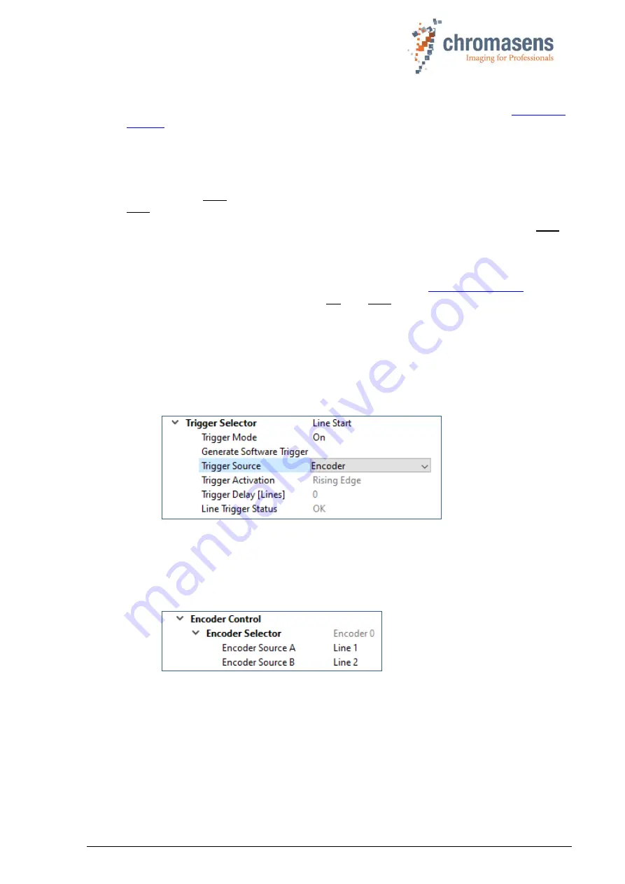
1. select
Line Start
in the
Trigger Selector
of the
Acquisition Control
feature group.
2. Set
Trigger Mode
to
On
.
3. Select
Encoder
as
Trigger Source
:
4. In the
Encoder Control
feature group, open
Encoder Selector.
5. Select the I/O lines the encoder is connected to as
Encoder Source A
and
Encoder
Source B,
e.g., when encoder output A is connected to camera input
Line 1
and
encoder output B is connected to camera input
Line 1
, encoder settings should look
like this:
6.
Encoder Mode
has two possible settings:
•
Four Phase
: The counter increments or decrements 1 for every full quadrature
cycle with jitter filtering.
•
High Resolution
: The counter increments or decrements every quadrature phase
for high resolution counting, but without jitter filtering.
7.
Encoder Output Mode
has two possible settings:
•
Motion:
Output pulses are generated in both directions.


