-31-
Mechanical Disassembly
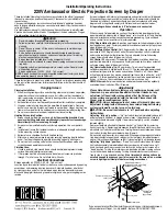
8-5 Optical unit disassembly-2
1 Remove 4 screws-A (M3x6) and take the Optical base top off.
2 Remove 1 screw-B(M3x8) and take the Optical lens holder off.
A
A
A
A
B
Optical base top
Optical lens
holder
Center
position
Relay lens(2)
Relay lens(1)
Relay lens(3)
Prism(TIR)
(M3x6)x4
(M3x6)x2
(M3x6)x2
(M3x6)x2
(M3x6)x2
Note:
As the prism(TIR) is a very sensitive com-
ponent, never touch or wipe the surface of
prism(TIR). If there are some dust particles
on the prism(TIR) surface, use the air spray
to remove them.
DS+750 Service Manual
020-000211-01 Rev. 1 (06-2009)
Содержание DS+750
Страница 1: ...DS 750 S E R V I C E M A N U A L 020 000211 01...
Страница 2: ......
Страница 47: ...45 Electrical Adjustment Test Points and Locations K66S 1 7 DS 750 Service Manual 020 000211 01 Rev 1 06 2009...
Страница 152: ...150 IC Block Diagrams L BA7078AF Sync Sep IC5321 L M62393FP DAC IC7801 DS 750 Service Manual 020 000211 01 Rev 1 06 2009...
Страница 154: ...152 IC Block Diagrams L K4S641632K SDRAM IC3401 L PW392 Scaler IC301 DS 750 Service Manual 020 000211 01 Rev 1 06 2009...
Страница 210: ......
Страница 224: ......